This thread has been locked.

If you have a related question, please click the "Ask a related question" button in the top right corner. The newly created question will be automatically linked to this question.

AM4379: GPIO interrupt on both edges

Part Number: AM4379

Hi,

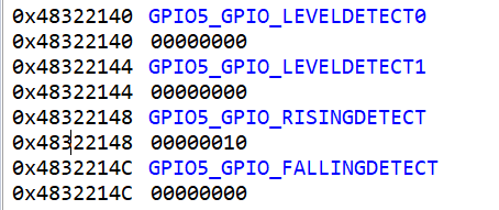
lm trying to capture an interrupt for both edges but the interrupt is only generated for the falling edge although i've set the GPIO related bit in the GPIO_RISINGDETECT and GPIO_FALLINGDETECT register.

The Pin im using is K22 (GPIO0_12). Is there anyhting else to do but the following:

1.) set GPIO0_12 as an input

2.) set bit 12 in GPIO_RISINGDETECT and GPIO_FALLINGDETECT

3.) clear the interrupt flag by setting bit 12 in GPIO_IRQSTS_0

4.) activate the interrupt by setting bit 12 in GPIO_IRQSTS_SET

5.) setup of a new hwi (index 128)

6.) put 3.) in the ISR

The code works fine for falling edge interrupts. I just got issues with rising edge interrupts.

Best regards,

Michael

  • Hi,

    What software is this?
  • It's testcode for an existing RTOS project. I know that there are RTOS drivers around to do this but i want to achieve it without touching the GPIO configuration in the existing project.

    I've already checked if the register values are set like i want them to be set and everything seems fine. It just does't want to trigger on the rising edge.

  • Update: I've tested this with der TI RTOS GPIO driver and im getting the same result. Setting the interrupt setting to RISINGEDGE doesnt change anything either. Does GPIO0 (especially on pin 12 and 13) support rising edge detection at all? I did not find anything in the TRM / Datasheet which is explaining my result.
  • Hi,

    I think raising edge should work as the failing edge. You mentioned the TI RTOS example used for this test. Can you clarify which one? Is it GPIO_LedBlink_evmAM437x_armTestProject in the latest pdk_am437x_1_0_10\packages\ti\drv\gpio\test\led_blink?

    As you can see that:
    #define GPIO_USER0_LED_PIN_NUM (0x0B)
    #define GPIO_USER0_LED_PORT_NUM (0x05)
    #define GPIO_USER1_LED_PIN_NUM (0x0A)
    #define GPIO_USER1_LED_PORT_NUM (0x05)


    /* GPIO Driver board specific pin configuration structure */
    GPIO_PinConfig gpioPinConfigs[] = {
    /* Input pin with interrupt enabled */
    GPIO_DEVICE_CONFIG(( GPIO_USER0_LED_PORT_NUM + 1 ), GPIO_USER0_LED_PIN_NUM) |
    GPIO_CFG_IN_INT_RISING | GPIO_CFG_INPUT,

    /* Output pin */
    GPIO_DEVICE_CONFIG( (GPIO_USER0_LED_PORT_NUM + 1), GPIO_USER0_LED_PIN_NUM) |
    GPIO_CFG_OUTPUT
    };

    Can you make sure this work on your setup? Then you can change the input pin to GPIO0_12 or 13. You need to make sure GPIO0_12 is setup correctly in pinmux.

    Regards, Eric
  • Hi Eric,

    thanks for your response. Im not using this example but the profinet_irt projekt. But i've now tried your example, to make sure that nothing interferes with my testing. Im working on the AM437x IDK and therefore changed the pins in the GPIO pin configuration.

    GPIO pins i've testet:

    GPIO0_12
    GPIO0_13
    GPIO4_14

    None of those are generating rising edge interrupts.

    GPIO_CFG_IN_INT_FALLING works just fine
    GPIO_CFG_IN_INT_RISING doesn't work at all
    GPIO_CFG_IN_INT_BOTH_EDGES only generates interrupts for the falling edge

    Reading the input register and generating falling edge interrupts works on all of them.

    What i've changed in the led_blink project:

    #define GPIO_USER0_LED_PIN_NUM (0x0C) //Pin12
    #define GPIO_USER0_LED_PORT_NUM (0x00) //GPIO0
    #define GPIO_USER1_LED_PIN_NUM (0x0D) //Pin13
    #define GPIO_USER1_LED_PORT_NUM (0x00) //GPIO0


    /* GPIO Driver board specific pin configuration structure */
    GPIO_PinConfig gpioPinConfigs[] = {
    /* Input pin with interrupt enabled */
    GPIO_DEVICE_CONFIG(( GPIO_USER0_LED_PORT_NUM + 1 ), GPIO_USER0_LED_PIN_NUM) |
    GPIO_CFG_IN_INT_RISING | GPIO_CFG_INPUT,

    /* Output pin */
    GPIO_DEVICE_CONFIG( (GPIO_USER1_LED_PORT_NUM + 1), GPIO_USER1_LED_PIN_NUM) |
    GPIO_CFG_OUTPUT
    };

    and my pinmux:

    //configuration of Pad K22 and L22 as GPIO0_12 ((input, pulldown resistor) / enable interrupt generation on this port) and GPIO0_13 (output)
    *((unsigned int*) 0x44E10978) = ((1<<18) | (1<<24) | (1<<25) | (1<<27) | 0x7); //pinmux K22
    *((unsigned int*) 0x44E1097C) = ((1<<18) | (1<<24) | (1<<25) | (1<<27) | 0x7); //pinmux L22

    callback:

    void AppGpioCallbackFxn(void)
    {
    /* Toggle LED1 */
    GPIO_toggle(USER_LED1);
    gpio_intr_triggered = 1;
    }

    Regards,
    Michael
  • Hi Michael,

    I tested and confirmed that gpio0_12 worked by using raising edge to generate an interrupt on AM437x. Here I describe my details:

    • SW: ti\pdk_am437x_1_0_10\packages\MyExampleProjects\GPIO_LedBlink_evmAM437x_armTestProject
    • HW: TI AM437x GP EVM (note, I don't have AM437x IDK EVM, but we are debugging certain GPIO IP for certain pins, they should same)

    Step 1, in the \GPIO_evmAM437x_board.c

    GPIO_PinConfig gpioPinConfigs[] = {

       /* Input pin with interrupt enabled */

       GPIO_DEVICE_CONFIG(( GPIO_USER0_LED_PORT_NUM + 1 ), GPIO_USER0_LED_PIN_NUM) |

       GPIO_CFG_IN_INT_RISING | GPIO_CFG_INPUT,

       /* Output pin */

       GPIO_DEVICE_CONFIG( (GPIO_USER1_LED_PORT_NUM + 1), GPIO_USER1_LED_PIN_NUM) |

       GPIO_CFG_OUTPUT

    };

    The original code used USER0 for the second GPIO instance, this doesn't make sense to me. So I changed them into USER1. The whole idea is the first GPIO instance generate interrupt (USER0), the second GPIO instance toggle a LED on EVM for visualization (USER1). 

    The original GPIO used:

    #define GPIO_USER0_LED_PIN_NUM (0x0B) 
    #define GPIO_USER0_LED_PORT_NUM (0x05) 

    #define GPIO_USER1_LED_PIN_NUM (0x0A)
    #define GPIO_USER1_LED_PORT_NUM (0x05)

    I verified that with above USER0---->USER1 change, the LED still blinking.

    Step 2:

    In the first GPIO instance, I changed GPIO_CFG_IN_INT_RISING to GPIO_CFG_IN_INT_FAILING, I confirmed this still working.

    I also recorded PINMUX for:

    • GPIO5_10: 0x44E10A40 = 0x13070007
    • GPIO5_11: 0x44E10A44 = 0x13070007

    Step 3: Now I want to verify the GPIO0_12 failing edge still work:

    So I changed:

    #define GPIO_USER0_LED_PIN_NUM (0x0C) //0xb
    #define GPIO_USER0_LED_PORT_NUM (0x00) //0x5
    #define GPIO_USER1_LED_PIN_NUM (0x0A)
    #define GPIO_USER1_LED_PORT_NUM (0x05)

    and 

    #define GPIO_INTR_LED_BASE_ADDR (SOC_GPIO0_REG) /*SOC_GPIO5_REG*/
    #define GPIO_LED_PIN_NUM (0xCU) /*0xB*/

    I still kept the USER1 (the second GPIO instance unchanged).

    Also, I changed PINMUX of GPIO0_12 0x44E10978 = 0x13070007 (some difference from your setting, please decode and check )

    I verified the the LED is still blinking.

    Step 4: 

    I changed LED0 from FAILING edge to RISING_EDGE, the LED still blinking. I double checked 0x44e07148 that BIT 12 set, 0x44e0714C is zero. This confirmed that GPIO0_12 rising edge can properly trigger interrupt on AM437x.

    Regards, Eric 

  • test_project.zipHi Eric,

    thank you for your effort to resolve my problem. I've gone through all of your steps and i think that my software is working correctly.

    It is setting the rising and falling edge detection registers of the GPIO bank but none of the possible combinations is generating rising edge interrupts.

    1. Rising Edge detection configuration: NOK - The interrupt is generated with the falling edge while the GPIO interrupt register states rising edge
    2. Falling Edge detection configuration: OK - The interrupt is generated with the falling edge and the GPIO interrupt register states falling edge
    3. Rising and Falling Edge detection configuration: NOK – Two interrupts are generated with the falling edge and the GPIO interrupt registers states rising and falling edge.

    I've attached my modified test project and some measurements to this post.

    The measurements are taken with a signal generator and a logic analyzer. D1 shows the input signal which is connected to the interrupt enabled pin. D2 is an GPIO output which is toggled every time the ISR is called.The test signal is a 100 Hz rectangular wave (0V low, 3.3V high).

    Regards,

    Michael

  • Mike,

    Can you confirm that your test is on AM437x IDK EVM, because we don't have any GPIO toggle example on that platform. Then, for the GPIO0_12, how do you physically access it to make it low or high?

    Regards, Eric
  • Eric,

    yes i am testing everything on the AM437x IDK EVM (this one www.ti.com/.../tmdsidk437x) as i do not have a GP EVM.
    My first test (before asking this question in the forum) was not using the demo and later tests with the demo did not fix it. I've muxed GPIO0_12 to ball nr. K22 which is (in the AM437x IDK schematic) connected to R387 which i have desoldered. The signal is then bluewired to a pinheader and sourced from a generator. Another option would be to desolder R245 and solder in R246 to map it to pin 43 of J16. I am using those pins because i am working on a project which is already connecting most of the pins of J16 and J1. GPIO0_13 has also been bluewired to a pinheader. I've tested both pins functionality (output and input). The only thing which is not working is the rising edge interrupt.

    Regards,
    Michael
  • Michael,

    Modifying the EVM is hard for me. Do you know if there options in the expansion connector or industrial I/O connector that I can have access to GPIO0_12/13 via pinmux, in case you explored that? And do you find other GPIO pins raising edge didn't work? Or you confirmed some other pins worked?

    Regards, Eric
  • Eric,

    i've now tried GPIO5_4 (ball P25, pinmux register spi4_sclk, connector J16_6) because it is accessible and not sharing the signal with anything else on the board.
     
    It behaves just like GPIO0_12.
     
    Regards,
     
    Michael

  • Michael,

    Thanks for letting me know that you tested GPIO5_4 which showed the same issue. This make my work easier.  Below I summarize my test:

    1. I used your attached CCS example and code, this is for AM437x GP EVM, I run it directly on AM437x IDK EVM, this may use a different PINMUX setting , here we only care about the PINMUX for GPIO part.

    2.1 I changed the to GPIO5_4

    #define GPIO_USER0_LED_PIN_NUM    (0x04)

    #define GPIO_USER0_LED_PORT_NUM   (0x05)

    2.2 Added a PINMUX for CTRL_CONF_SPI4_SCLK

       *(unsigned int*) 0x44E10A50 = 0x00060007; //  =====> this is pull-up, receive mode,

    2.3 In the ISR I added a counter

    Attached two files you can we what I changed.

    3. My goal is to prove that RISING EDGE can trigger ISR so the counter increase.

    4. To do that, I put a wire into J16_6 (GPIO5_4) and another wire into J16_60 (this is ground). When I shorten two wires, this is a failing edge as it grounded. When I disconnect two wires, J16_6 goes high, this is a rising edge.

    5. I was able to get multiple ISR triggered (gpio_intr_triggered increase) when I connect/disconnect two wires. I confirmed I only have rising edge interrupt:

    /**
     *  \file   main.c
     *
     *  \brief  Example application main file. This application will toggle the led.
     *          The led toggling will be done inside an callback function, which
     *          will be called by Interrupt Service Routine. Interrupts are
     *          triggered manually and no external source is used to trigger
     *          interrupts.
     *
     */
    
    /*
     * Copyright (C) 2014 - 2016 Texas Instruments Incorporated - http://www.ti.com/
     *
     * Redistribution and use in source and binary forms, with or without
     * modification, are permitted provided that the following conditions
     * are met:
     *
     * Redistributions of source code must retain the above copyright
     * notice, this list of conditions and the following disclaimer.
     *
     * Redistributions in binary form must reproduce the above copyright
     * notice, this list of conditions and the following disclaimer in the
     * documentation and/or other materials provided with the
     * distribution.
     *
     * Neither the name of Texas Instruments Incorporated nor the names of
     * its contributors may be used to endorse or promote products derived
     * from this software without specific prior written permission.
     *
     * THIS SOFTWARE IS PROVIDED BY THE COPYRIGHT HOLDERS AND CONTRIBUTORS
     * "AS IS" AND ANY EXPRESS OR IMPLIED WARRANTIES, INCLUDING, BUT NOT
     * LIMITED TO, THE IMPLIED WARRANTIES OF MERCHANTABILITY AND FITNESS FOR
     * A PARTICULAR PURPOSE ARE DISCLAIMED. IN NO EVENT SHALL THE COPYRIGHT
     * OWNER OR CONTRIBUTORS BE LIABLE FOR ANY DIRECT, INDIRECT, INCIDENTAL,
     * SPECIAL, EXEMPLARY, OR CONSEQUENTIAL DAMAGES (INCLUDING, BUT NOT
     * LIMITED TO, PROCUREMENT OF SUBSTITUTE GOODS OR SERVICES; LOSS OF USE,
     * DATA, OR PROFITS; OR BUSINESS INTERRUPTION) HOWEVER CAUSED AND ON ANY
     * THEORY OF LIABILITY, WHETHER IN CONTRACT, STRICT LIABILITY, OR TORT
     * (INCLUDING NEGLIGENCE OR OTHERWISE) ARISING IN ANY WAY OUT OF THE USE
     * OF THIS SOFTWARE, EVEN IF ADVISED OF THE POSSIBILITY OF SUCH DAMAGE.
     *
     */
    
    
    #ifndef BARE_METAL
    /* XDCtools Header files */
    #include <xdc/std.h>
    #include <xdc/cfg/global.h>
    #include <xdc/runtime/System.h>
    #include <xdc/runtime/Error.h>
    
    
    /* BIOS Header files */
    #include <ti/sysbios/BIOS.h>
    #include <ti/sysbios/knl/Task.h>
    #endif
    
    #include <stdio.h>
    
    /* TI-RTOS Header files */
    #include <ti/drv/gpio/GPIO.h>
    #include <ti/drv/gpio/soc/GPIO_soc.h>
    
    #include "GPIO_log.h"
    #include "GPIO_board.h"
    
    #include <ti/board/board.h>
    
    /**********************************************************************
     ************************** Macros ************************************
     **********************************************************************/
    #if defined(SOC_AM574x) || defined(SOC_AM572x) || defined (SOC_AM571x)
    #if defined (__TI_ARM_V7M4__)
    #define DELAY_VALUE       (0x6FFFFFU) /* Update Delay as it is not sufficent for M4 core */
    #else
    #define DELAY_VALUE       (0x6FFFFFU)
    #endif
    #else
    #define DELAY_VALUE       (0x6FFFFFU)
    #endif
    
    /**********************************************************************
     ************************** Internal functions ************************
     **********************************************************************/
    
    /* Delay function */
    void AppDelay(unsigned int delayVal);
    
    /* Callback function */
    void AppGpioCallbackFxn(void);
    
    #if defined(idkAM574x) || defined(idkAM572x) || defined(idkAM571x)
    /* GPIO clock and pinmux configurations */
    extern void AppGPIOInit(void);
    #endif
    
    #if defined(idkAM574x) || defined(idkAM572x)
    extern void GPIOApp_UpdateBoardInfo(void);
    extern void GPIOAppUpdateConfig(uint32_t *gpioBaseAddr, uint32_t *gpioPin);
    #endif
    
    /*
     *  ======== Board_initI2C ========
     */
    static void Board_initGPIO(void)
    {
        Board_initCfg boardCfg;
    
    #if defined(SOC_K2H) || defined(SOC_K2K) || defined(SOC_K2E) || defined(SOC_K2L) || defined(SOC_K2G) || defined(SOC_C6678) || defined(SOC_C6657) || defined(SOC_OMAPL137) || defined(SOC_OMAPL138)
        GPIO_v0_HwAttrs gpio_cfg;
    
        /* Get the default SPI init configurations */
        GPIO_socGetInitCfg(GPIO_LED0_PORT_NUM, &gpio_cfg);
    
        /* Modify the default GPIO configurations if necessary */
    
        /* Set the default GPIO init configurations */
        GPIO_socSetInitCfg(GPIO_LED0_PORT_NUM, &gpio_cfg);
    
    #if defined(SOC_K2G)
        /* Setup GPIO interrupt configurations */
        GPIO_socSetIntMux(GPIO_LED0_PORT_NUM, GPIO_LED0_PIN_NUM, NULL, GPIO_MUX_SEL);
    #endif
    #if defined(SOC_OMAPL137) || defined(SOC_OMAPL138)
        /* Setup GPIO interrupt configurations */
        GPIO_socSetBankInt(GPIO_LED0_PORT_NUM, GPIO_LED0_PIN_NUM, NULL);
    #endif
    #endif
    
    #if defined(evmK2E) || defined(evmC6678)
        boardCfg = BOARD_INIT_MODULE_CLOCK |
            BOARD_INIT_UART_STDIO;
    #else
        boardCfg = BOARD_INIT_PINMUX_CONFIG |
            BOARD_INIT_MODULE_CLOCK |
            BOARD_INIT_UART_STDIO;
    #endif
        Board_init(boardCfg);
    
    #if defined(idkAM572x) || defined(idkAM574x)
        GPIOApp_UpdateBoardInfo();
    #endif
    }
    
    /**********************************************************************
     ************************** Global Variables **************************
     **********************************************************************/
    volatile uint32_t gpio_intr_triggered = 0;
    uint32_t gpioBaseAddr;
    uint32_t gpioPin;
    
    /*
     *  ======== test function ========
     */
    #ifndef BARE_METAL
    void gpio_test(UArg arg0, UArg arg1)
    {
    #else
    void main()
    {
        Board_initGPIO();
    #endif
        uint32_t testOutput = 1;
    
        //configuration of Pad K22 and L22 as GPIO0_12 ((input, pulldown resistor) / enable interrupt generation on this port) and GPIO0_13 (output)
    //    *((unsigned int*) 0x44E10978)      =  ((1<<18) | (1<<24) | (1<<25) | (1<<27) | 0x7); //pinmux K22
    //    *((unsigned int*) 0x44E1097C)      =  ((1<<18) | (1<<24) | (1<<25) | (1<<27) | 0x7); //pinmux L22
        *((unsigned int*) 0x44E10978)       =   0x13070007; // set: 28, 25, 24, 18, 17, 16 | 0x7
        *((unsigned int*) 0x44E1097C)       =   0x13070007;
    
        /* GPIO initialization */
        GPIO_init();
    
        /* Set the callback function */
        GPIO_setCallback(USER_LED0, AppGpioCallbackFxn);
    
        /* Enable GPIO interrupt on the specific gpio pin */
        GPIO_enableInt(USER_LED0);
    
        /* Write high to gpio pin to control LED1 */
        GPIO_write((USER_LED1), GPIO_PIN_VAL_HIGH);
        AppDelay(DELAY_VALUE);
    
        GPIO_log("\n GPIO Led Blink Application \n");
    
    #if defined(SOC_K2L) || defined(SOC_C6678) || defined(SOC_C6657)
        /* No GPIO pin directly connected to user LED's on K2L/K2G/C6678/C6657 EVM, just trigger interrupt once */
        GPIO_toggle(USER_LED0);
        while (!gpio_intr_triggered);
    
        UART_printStatus("\n All tests have passed \n");
    #else
    
        while(1)
        {
    #if defined(SOC_AM574x) || defined(SOC_AM572x) || defined(SOC_AM571x)|| defined(SOC_AM335x) || defined(SOC_AM437x)
    
    #if defined (idkAM572x) || defined (idkAM574x)
            /* Update GPIO info based on the board */
            GPIOAppUpdateConfig(&gpioBaseAddr, &gpioPin);
    #else
            gpioBaseAddr = GPIO_BASE_ADDR;
            gpioPin      = GPIO_LED_PIN;
    #endif
    //        /* Trigger interrupt */
    //        GPIOTriggerPinInt(gpioBaseAddr, 0, gpioPin);
    #endif
    #if defined(SOC_K2H) || defined(SOC_K2K) || defined(SOC_K2E) || defined(SOC_K2G) || defined(SOC_OMAPL137) || defined(SOC_OMAPL138)
            GPIO_toggle(USER_LED0);
    #endif
    //        AppDelay(DELAY_VALUE);
    //        if (testOutput)
    //        {
    //            UART_printStatus("\n All tests have passed \n");
    //            testOutput = 0;
    //        }
        }
    #endif
        Task_exit();
    }
    
    #ifndef BARE_METAL
    /*
     *  ======== main ========
     */
    int main(void)
    {
        /* Call board init functions */
        Board_initGPIO();
    
    #if defined(idkAM574x) || defined(idkAM572x) || defined(idkAM571x)
        AppGPIOInit();
    #endif
    
        /* Start BIOS */
        BIOS_start();
        return (0);
    }
    #endif
    
    /*
     *  ======== AppDelay ========
     */
    void AppDelay(unsigned int delayVal)
    {
        while(delayVal)
        {
            delayVal--;
        }
    }
    
    /*
     *  ======== Callback function ========
     */
    void AppGpioCallbackFxn(void)
    {
        /* Toggle LED1 */
        GPIO_toggle(USER_LED1);
    //    AppDelay(DELAY_VALUE);
        gpio_intr_triggered = 1;
    }


    /**
     *  \file   GPIO_evmAM572x_board.c
     *
     *  \brief  AM572x GP EVM board specific GPIO parameters.
     *
     */
    
    /*
     * Copyright (C) 2014 Texas Instruments Incorporated - http://www.ti.com/
     *
     * Redistribution and use in source and binary forms, with or without
     * modification, are permitted provided that the following conditions
     * are met:
     *
     * Redistributions of source code must retain the above copyright
     * notice, this list of conditions and the following disclaimer.
     *
     * Redistributions in binary form must reproduce the above copyright
     * notice, this list of conditions and the following disclaimer in the
     * documentation and/or other materials provided with the
     * distribution.
     *
     * Neither the name of Texas Instruments Incorporated nor the names of
     * its contributors may be used to endorse or promote products derived
     * from this software without specific prior written permission.
     *
     * THIS SOFTWARE IS PROVIDED BY THE COPYRIGHT HOLDERS AND CONTRIBUTORS
     * "AS IS" AND ANY EXPRESS OR IMPLIED WARRANTIES, INCLUDING, BUT NOT
     * LIMITED TO, THE IMPLIED WARRANTIES OF MERCHANTABILITY AND FITNESS FOR
     * A PARTICULAR PURPOSE ARE DISCLAIMED. IN NO EVENT SHALL THE COPYRIGHT
     * OWNER OR CONTRIBUTORS BE LIABLE FOR ANY DIRECT, INDIRECT, INCIDENTAL,
     * SPECIAL, EXEMPLARY, OR CONSEQUENTIAL DAMAGES (INCLUDING, BUT NOT
     * LIMITED TO, PROCUREMENT OF SUBSTITUTE GOODS OR SERVICES; LOSS OF USE,
     * DATA, OR PROFITS; OR BUSINESS INTERRUPTION) HOWEVER CAUSED AND ON ANY
     * THEORY OF LIABILITY, WHETHER IN CONTRACT, STRICT LIABILITY, OR TORT
     * (INCLUDING NEGLIGENCE OR OTHERWISE) ARISING IN ANY WAY OUT OF THE USE
     * OF THIS SOFTWARE, EVEN IF ADVISED OF THE POSSIBILITY OF SUCH DAMAGE.
     *
     */
    #include <stdio.h>
    #include <ti/drv/gpio/GPIO.h>
    #include <ti/csl/soc.h>
    #include <ti/drv/gpio/soc/GPIO_soc.h>
    
    #define GPIO_USER0_LED_PIN_NUM    (0x0C)
    #define GPIO_USER0_LED_PORT_NUM   (0x00)
    #define GPIO_USER1_LED_PIN_NUM    (0x0D)
    #define GPIO_USER1_LED_PORT_NUM   (0x00)
    
    
    /* GPIO Driver board specific pin configuration structure */
    GPIO_PinConfig gpioPinConfigs[] = {
        /* Input pin with interrupt enabled */
        GPIO_DEVICE_CONFIG(( GPIO_USER0_LED_PORT_NUM + 1 ), GPIO_USER0_LED_PIN_NUM) |
        GPIO_CFG_IN_INT_RISING | GPIO_CFG_INPUT,
    
        /* Output pin */
        GPIO_DEVICE_CONFIG( (GPIO_USER1_LED_PORT_NUM + 1), GPIO_USER1_LED_PIN_NUM) |
        GPIO_CFG_OUTPUT
    };
    
    /* GPIO Driver call back functions */
    GPIO_CallbackFxn gpioCallbackFunctions[] = {
        NULL,
        NULL
    };
    
    /* GPIO Driver configuration structure */
    GPIO_v1_Config GPIO_v1_config = {
        gpioPinConfigs,
        gpioCallbackFunctions,
        sizeof(gpioPinConfigs) / sizeof(GPIO_PinConfig),
        sizeof(gpioCallbackFunctions) / sizeof(GPIO_CallbackFxn),
        0,
        };
    

    Can you confirm my finding?

    Regards, Eric

  • Eric,

    i can confirm your results. Your test behaves different because you are getting glitches from mechanically connecting 2 wires together.

    Using a signal generator or another GPIO to generate a clean edge will give the results i've described earlier.

    Regards,

    Michael

  • Eric,

    i've got it sorted out. It seems like my signal source is errornous. Looking at it with the logic analyzer does not show that there is an issue but after looking at it with a scope i found that it is not pulling the signal all the way to ground. I did not see that in the beginning because i just had a look at the high voltage level and not the low voltage level. The signal was perfectly square but also offset from ground. This was still sufficient for the falling edge trigger but would not trigger the rising edge as the comperators window for it is shiftet.

    Thank you for helping me out with this.

    Best Regards,
    Michael