This thread has been locked.

If you have a related question, please click the "Ask a related question" button in the top right corner. The newly created question will be automatically linked to this question.

RTOS/AM5728: GPIO control from DSP

Part Number: AM5728

Tool/software: TI-RTOS

Hi:

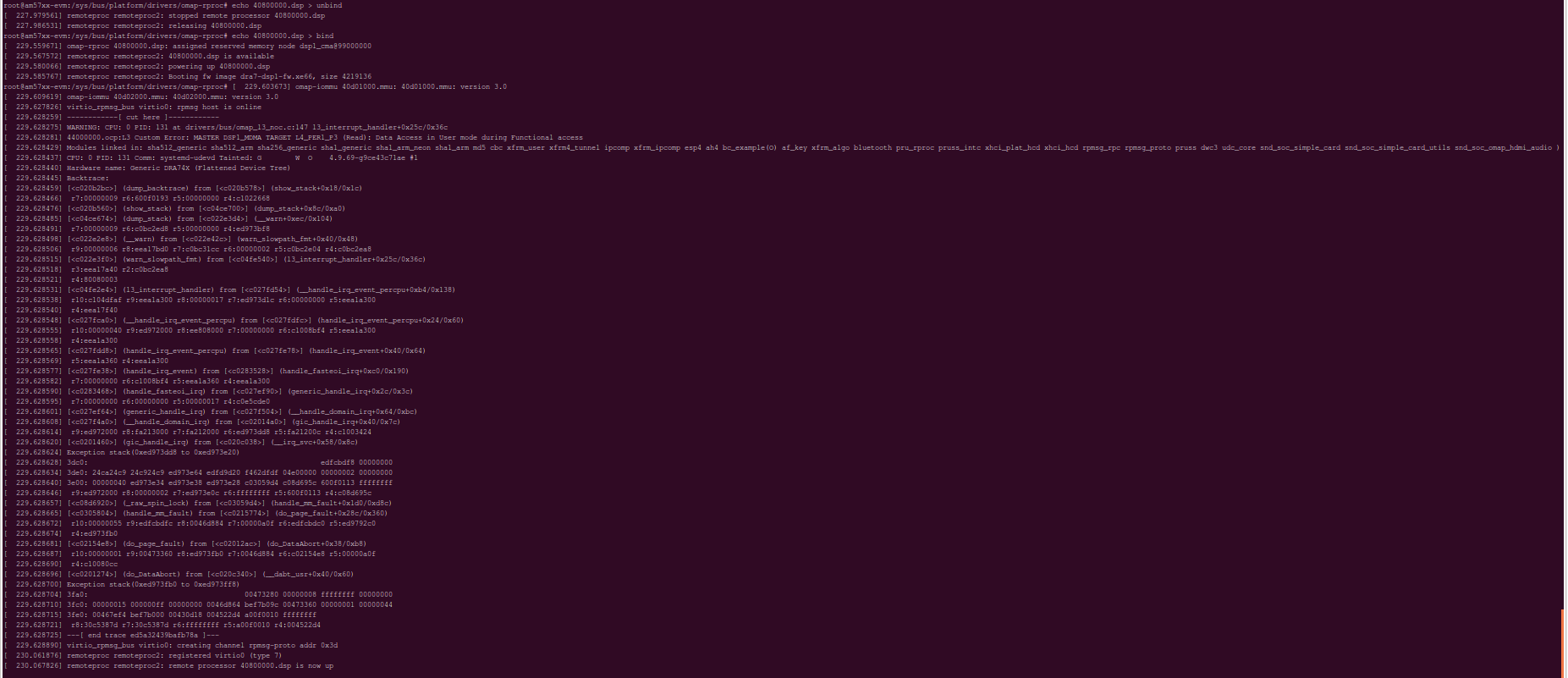
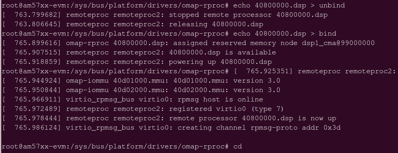
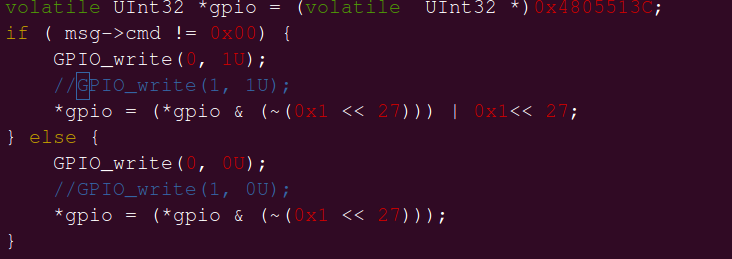
 When I operated GPIO2_27 on the DSP terminal, I found that I couldn't control the high and low level.

GPIO2_27PIN:

root@am57xx-evm:~# devmem2 0x4A0034D4 

/dev/mem opened.
Memory mapped at address 0xb6f49000.
Read at address 0x4A0034D4 (0xb6f494d4): 0x0001000E

When I change the GPIO2_27 to GPIO4_4, I can control it at the DSP end.

Software version RTOS_4.3 AM5728

1856.Gpio.c
Fullscreen
1
2
3
4
5
6
7
8
9
10
11
12
13
14
15
16
17
18
19
20
21
22
23
24
25
26
27
28
29
30
31
32
33
34
35
36
37
38
39
40
41
42
43
44
45
46
47
48
49
50
51
52
53
54
55
56
57
58
59
60
61
62
63
64
65
66
67
#include <stdlib.h>
#include <xdc/std.h>
#include <xdc/runtime/Diags.h>
#include <xdc/runtime/Error.h>
#include <xdc/runtime/Log.h>
#include <xdc/runtime/System.h>
/* package header files */
#include <ti/ipc/Ipc.h>
#include <xdc/runtime/Registry.h>
#include <ti/ipc/MessageQ.h>
#include <ti/ipc/MultiProc.h>
#include <ti/sysbios/BIOS.h>
#include <ti/sysbios/knl/Task.h>
#include <ti/drv/gpio/GPIO.h>
#include <ti/drv/gpio/soc/GPIO_v1.h>
#include "../shared/AppCommon.h"
#define MODULE_NAME "Server"
/* module structure */
typedef struct {
UInt16 hostProcId; // host processor id
MessageQ_Handle slaveQue; // created locally
} Server_Module;
//GPIO4_4, GPIO4_9, GPIO2_27
GPIO_PinConfig gpioPinConfigs[] = {
GPIO_DEVICE_CONFIG(0x04, 0x04) | GPIO_CFG_OUTPUT,
GPIO_DEVICE_CONFIG(0x04, 0x09) | GPIO_CFG_OUTPUT,
GPIO_DEVICE_CONFIG(0x02, 0x27) | GPIO_CFG_OUTPUT,
GPIO_DEVICE_CONFIG(0x04, 0x03) | GPIO_CFG_OUTPUT
//GPIO_DEVICE_CONFIG(0x03, 0x28) | GPIO_CFG_OUTPUT,
//GPIO_DEVICE_CONFIG(0x03, 0x29) | GPIO_CFG_OUTPUT,
//GPIO_DEVICE_CONFIG(0x03, 0x30) | GPIO_CFG_OUTPUT,
};
/* GPIO Driver call back functions */
GPIO_CallbackFxn gpioCallbackFunctions[] = {
NULL,
NULL,
NULL
};
GPIO_v1_Config GPIO_v1_config = {
gpioPinConfigs,
NULL,
sizeof(gpioPinConfigs) / sizeof(GPIO_PinConfig),
//sizeof(gpioCallbackFunctions) / sizeof(GPIO_CallbackFxn),
0,
0,
};
Void MessageTask(UArg arg0, UArg arg1);
Int main(Int argc, Char* argv[])
{
Error_Block eb;
Task_Params taskParams;
XXXXXXXXXXXXXXXXXXXXXXXXXXXXXXXXXXXXXXXXXXXXXXXXXX

  • The RTOS team have been notified. They will respond here.
  • Hi,

    This looks to be an IPC communication between DSP and ARM? On the DSP side, when you task runs, it does some GPIO_write with different GPIO pins,

    GPIO_DEVICE_CONFIG(0x04, 0x04) | GPIO_CFG_OUTPUT,

    GPIO_DEVICE_CONFIG(0x04, 0x09) | GPIO_CFG_OUTPUT,

    GPIO_DEVICE_CONFIG(0x02, 0x27) | GPIO_CFG_OUTPUT,

    GPIO_DEVICE_CONFIG(0x04, 0x03) | GPIO_CFG_OUTPUT

    How do you determine that GPIO2_27PIN didn't work, but GPIO4_4 worked?

    From Read at address 0x4A0034D4 (0xb6f494d4): 0x0001000E, what PINMUX is used to control GPIO4_4? Can you also dump the same PINMUX register for comparison?

    What TI AM57x EVM used for this test? And if you just run the GPIO test standalone on DSP, without Linux, without IPC, do it work for this PIN? We have GPIO example under pdk_am57xx_1_0_x\packages\ti\drv\gpio\test\led_blink

    Regards, Eric
  • Hi:

     When I control GPIO4_4, I can detect high and low levels through the oscilloscope, but I can't detect it when I control GPIO2_27.

     From Read at address 0x4A0034D4 (0xb6f494d4): 0x0001000E, what PINMUX is used to control GPIO2_27.
    GPIO4_4 PINMUX:
     From Read at address 0x4A003574 (0xb6f49574): 0x0001000E, what PINMUX is used to control GPIO4_4
    U-BOOT   PINMUX  GPIO4_4、GPIO2_27 

    {VIN2A_D3, (M14 | PIN_OUTPUT_PULLDOWN)}, /* vin2a_d3.gpio4_4 */

    {GPMC_BEN1, (M14 | PIN_OUTPUT_PULLDOWN)}, /* gpmc_ben1.gpio2_27 */

    Thanks

  • Hi,

    Can you test standalone on DSP with GPIO 2_27, without Linux? I suspect the Linux caused the issue.

    Regards, Eric
  • HI:

    Linux situation may cause GPIO2_27 not available on the DSP side?

    When I change GPIO2_27 to GPIO8_21, I get the following error message.

    GPIO8_21 PIN

    When entering the following information, there is no error when loading firmware from the new one. What is going on?

    echo 245 > /sys/class/gpio/export

    echo out > /sys/clas/gpio/gpio245/direction

    cd /sys/bus/platform/drivers/omap-rproc

    echo 40800000.dsp > unbind

     echo 40800000.dsp > bind 

    Why is this again?

    Is the oscilloscope still unable to detect the GPIO8_21 pin level?

    Thanks

  • Hi,

    Just focus on GPIO2_27, can you try to run the C66 standalone without Linux on A15 side? I think you can do it by using CCS/JTAG to connect the DSP core, just load and run and measure if there is low/high level using your existing setup?

    Do you use TI EVM for this testing? If yes, is it an IDK EVM or GP EVM? How do you access GPIO2_27 physically?

    Regards, Eric
  • Any news?

    Regards, Eric
  • A15 terminal controls GPIO2_27 high and low level.

    Software version: TI_SDK 4.3, hardware version: AM5728-ES2.0, custom board

  • Hi,

    Below summarized how I test GPIO2_27 high/low on TI AM572x IDK EVM (www.ti.com/.../TMDXIDK5728):

    1. From AM5728 datasheet, the GPIO2_27 is connected to M4 ball of the chip and is controlled by CTRL_CORE_PAD_GPMC_BEN1 (0x4a00_34d4). I set this register to 0x0002_000E.

    2. I used TI AM572x IDK EVM for the test. From the schematic, GPIO2_27 is accessible from J21 pin 16. So I put a wire here and another wire on J21 pin 60 for ground.

    3. On 0x4805_5134 GPIO2_GPIO_OE, I cleared bit 27 so this enabled output.

    4. On 0x4805_513C GPIO2_GPIO_DATAOUT, I set bit 27 to 1, I saw a high output of 3.4V. I clear this bit 27 to 0, I saw a low output 0V.

    This doesn't matter where you run it, A15 core, C66x core, just look/modify the registers from CCS memory window. There is no such issue you reported that GPIO2_27 can't output a high level.

    TI EVM worked properly for this. Please check your own board schematic/design for any errors.

    Regards, Eric
  • Hi

    Thank you very much for your reply, I have tried this situation.

    I looked at the GPIO2_GPIO_OE, GPIO2_GPIO_DATAOUT register values, GPIO2_GPIO_OE Register 27bit is 0.

    GPIO_write(0, 1U) is called at the DSP end. The value of GPIO2_GPIO_DATAOUT  27bit is always 0, which is equivalent to GPIO_write.
    When the DSP side writes 0 or 1 to the 27th bit of 0x4805_513C, it can control the high and low levels.

    Thanks