This thread has been locked.

If you have a related question, please click the "Ask a related question" button in the top right corner. The newly created question will be automatically linked to this question.

TMS320C5505: clock generation in tms320c5505

Part Number: TMS320C5505
Other Parts Discussed in Thread: ADS1278

Dear,

i dont understand how do i generate the clock for external interfaces. since tms320c5505 does not have pwm. when i tried to genearte the clock using gpio using timer interrupt it hardly generates 3MHz where my requirement is 27MHz.

when i go for PLL i can generate the clock but how do i take pll configuration on GPIO???

what are the other ways to generate the clock..plz tell me..i got stuck due to this issue.

in my application ads1278 is interfaced to tms320c5505 where in low mode i need to serve 5.4MHz and high mode 37MHz..

i need 24 bit adc only.

or 

can u suggest me 24 bit adc which has self genrated clock

  • Please share which CSL version are you using?

    Best Regards,
    Yordan
  • c55_csl_3.04 and c55_csl_3.08
  • Hi Kanchan,

    Have you considered using a spare I2S_CLK to output these clocks?
    One catch with I2S is that it must divide by a power of two... I2Sn_CLK = SystemClock / (2CLKDIV+1).
    So to obtain these exact frequencies, you might need to adjust the System Clock frequency with the PLL.

    Regards,
    Mark
  • Hi,

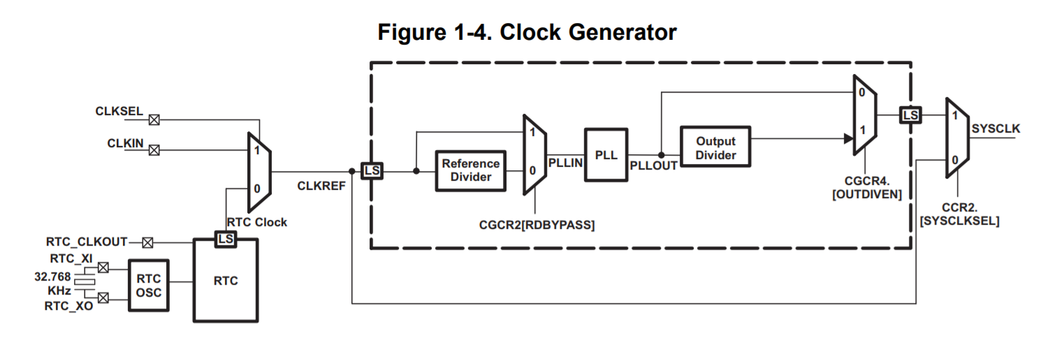
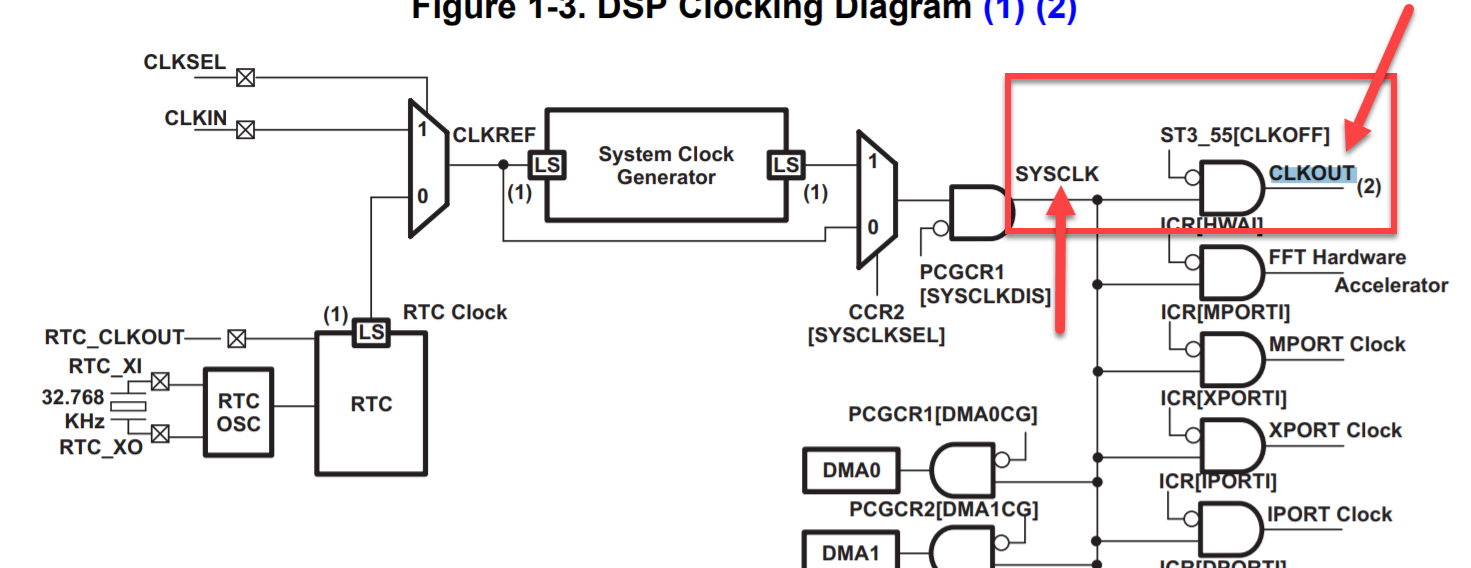
    There are two related parts. One is System Clock Generator and the other is ST3_55[CLKOFF] register to have control over CLKOUT pin. I attached some related images in order to show the relation between these two parts.

    In the image below, you can see the inner parts of the "System Clock Generator" unit.

    And the description:

    In the next two images below you can find how the  "System Clock Generator" is connected to CLKOUT and how its output driver could be disabled or enabled.

    For more information, you can take a look at this PDF  and see 1.4.2 Functional Description section.

  • ok i understood..
    but can i take this clkout pin on gpio? and can i adjust it according to my application like 5.4MHz, 27MHz or 37MHz.??
    if i do so (i got the procedure of PLL) can processor runs on the frequency which i set at the start up in .gll file or if i change the pll as per applicaton will processor frequency gets set to pll frequency which set
  • Hi Kanchan,

    You can only observe the SYSCLK on the CLKOUT pin. It cannot be routed to a GPIO.
    If you adjust the SYSCLK to 5.4MHz, 27MHz, or 37MHz, then the whole system will operate with a SYSCLK at the same frequency. This might be too slow to perform processing within a specific time. Futhermore, any peripherals that derive their clocks from the SYSCLK will also run slower.
    And the CLKOUT pin is not intended to be used by any other device. It is available for debugging purposes, so you can probe the frequency of the SYSCLK. It is not guaranteed to be glitch-free.

    You can configure the SYSCLK and CLKOUT pin in a GEL file or in source code. To enable the CLKOUT pin, set the CLKOFF bit in the ST3 system registers. I recommend you use some other clock like an unused I2S CLK, which can derive its frequency from SYSCLK with an integer, power of 2 divider.

    Regards,
    Mark