This thread has been locked.

If you have a related question, please click the "Ask a related question" button in the top right corner. The newly created question will be automatically linked to this question.

DRA7-EVM vin-1a related question

Other Parts Discussed in Thread: TVP5158

On our dra7-evm, we use pattern generator output NTSC signal to tvp-5158 and receive from vin-1a. We measure the vin-1a_clk signal through oscilloscope, the result like this =>           
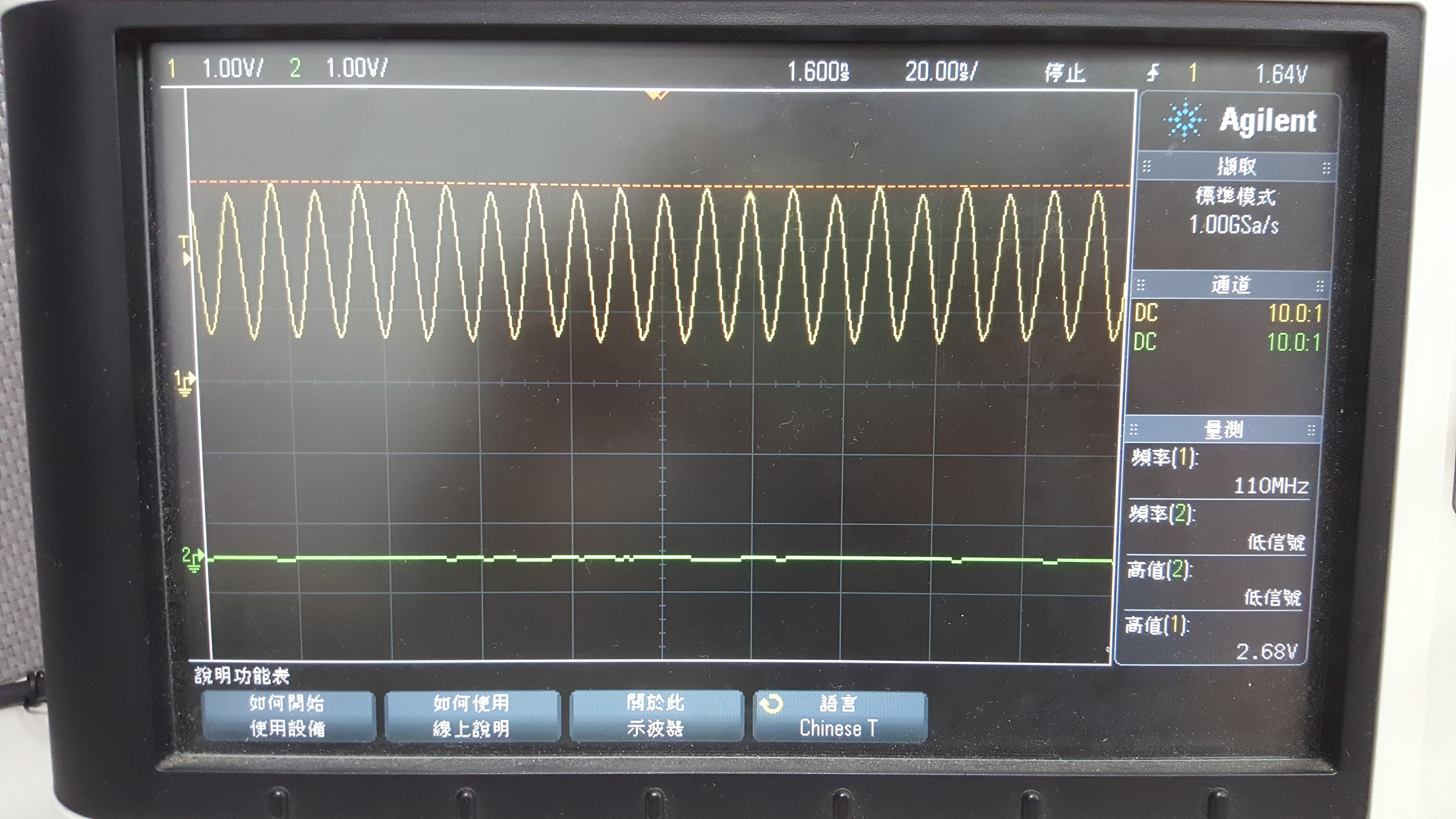
The voltage seems to be 2.7V maximum, and frequency is 107MHz.

I have few questions:

1. What is the correct voltage level for vin-1a, 3.3V or 1.8V? Is this selectable?

2. According to our measurement, the clock wave is not down to 0V, but wave up and down between 600mV to 2.7V. Why the low part of wave doesn't touch to 0V?

3. We generate 720 x 480@60 resolution signal to tvp-5158, then we measure the vin-1a_clk is 107MHz, is this the right frequency? What is the formulation to generate 107MHz based on 720 x 480@60 resolution?

4. At our custom board, we use another converter(analog adv7611), and we try to let it output BT656 8-bits 720 x 480 signal, we got about 26~27MHz clock output, is this normal? Because tvp-5158 also generate the same signal, but it's clock output is 107MHz.

Regards,

Shawn 

  • Hi shawm lin,
    I have a related question about Enable MMC3 interface,
    e2e.ti.com/.../688595
    How to solve this problem later?
    My question,
    e2e.ti.com/.../709887
    Any Reply wille be appreciated!
    Thanks!
  • Hi Shawn,

    First, I would like to confirm your setup - TVP-5158 is located on its own board which is connected to the EVM expansion port, i.e. its VIN1 pins. Is this correct?

    1. VIN1 pins can operate at either 1.8V or 3.3V. This is a feature of the SoC itself. On EVM, VIN1 is assigned to a 3.3V network. With a different PCB design, 1.8V could be selected, but note that this will effect MMC1 too.

    2. I'm not familiar enough with the TVP-5158 chip.  From what I read in the datasheet and from the sine waveform on your screenshot, I can conclude that TVP-5158 is outputting a differential clock. Whereas VIN is accepting a single-ended clock only. You could use some converter to fix that.

    3. 27 MHz should be enough for that resolution. But  I'm not an expert in display protocols, I just used a simple web tool for video clock calculation.

    4. This could be matter of TCP-5158 configuration (via I2C) of the resolution and data format?

    Regards,

    Stan

  • Hi Stan,

    Thanks for your reply.

    Stanislav Stilyanov said:
    First, I would like to confirm your setup - TVP-5158 is located on its own board which is connected to the EVM expansion port, i.e. its VIN1 pins. Is this correct?

    TVP-5158 is located on JAMR3 board, and connect with EVM board through connector.

    Stanislav Stilyanov said:
    2. I'm not familiar enough with the TVP-5158 chip.  From what I read in the datasheet and from the sine waveform on your screenshot, I can conclude that TVP-5158 is outputting a differential clock. Whereas VIN is accepting a single-ended clock only. You could use some converter to fix that.

    If the TVP-5158 outputting differential clock, then there must have a pair clock output pins, can you tell me where should i measure on EVM? Because through EVM schematic, what i am measureing is resistor R195 on EVM board.

    Currently, i can use VIN-1A to receive TVP-5158 signal, so i think the EVM board should fix differential-to-single ended clock already.

    Regards,

    Shawn

  • Shawn,

    Ok, I understand now for the JAMR board.

    Looking closer to datasheet (5.8 Video Output Clock and Data Timing), it seems that OCLK_P output is single ended. The oval waveform can be due to long distance/wire capacitance and/or scope probe added capacitance.

    What is the exact issue you are facing?

    Regards,

    Stan

  • Hi Stan,

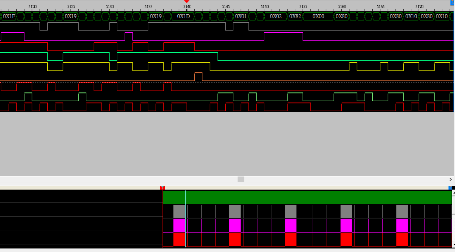
    At evm board, i can use vin-1A to capture TVP-5158 BT656 video signal. So i use logic analyzer to measure the BT656 signal, but i can't find any formal SAV(Start of Active Video, with 4 bytes, 0xff, 0, 0, xx) and EAV(End of Active Video, with 4 bytes, 0xff, 0, 0, xx) signal. So i'm curious why the vin-1A still can captch the video.

    Below is the result from logic analyzer, i capture the section which EAV and SAV should appear, but it didn't.

    EAV(i believe it should be) =>       

    SAV(i believe it should be) =>         

    Regards,

    Shawn

  • Hi Shawn,

    Regarding the clock, TVP5158 is configured for line interleaved multiplexed video.
    That's why the clock is 4times faster than expected. It is transferring video data from 4 channels line by line

    Nikhil D