This thread has been locked.

If you have a related question, please click the "Ask a related question" button in the top right corner. The newly created question will be automatically linked to this question.

RTOS/TDA2P-ACD: McSPI3 Not Working on Custom TDA2P Board

Part Number: TDA2P-ACD

Tool/software: TI-RTOS

Hello All,

We have configured McSPI3 as shown below in our "platform_tda2xx_pad_config.c" file in PSDK 03.03,

    HW_WR_REG32(SOC_CORE_PAD_IO_REGISTERS_BASE + CTRL_CORE_PAD_MCASP1_AXR8,                            //SCLK
                0xc0003);
    HW_WR_REG32(SOC_CORE_PAD_IO_REGISTERS_BASE + CTRL_CORE_PAD_MCASP1_AXR9,                           //MOSI
                0xc0003);
    HW_WR_REG32(SOC_CORE_PAD_IO_REGISTERS_BASE + CTRL_CORE_PAD_MCASP1_AXR10,                         //MISO
                0xc0003);
    HW_WR_REG32(SOC_CORE_PAD_IO_REGISTERS_BASE + CTRL_CORE_PAD_MCASP1_AXR11,                        //CS0-Acceleromter
                0x60003);
     HW_WR_REG32(SOC_CORE_PAD_IO_REGISTERS_BASE + CTRL_CORE_PAD_MCASP1_AXR12,                       //CS1-Gyro
                0x60003);
    HW_WR_REG32(SOC_CORE_PAD_IO_REGISTERS_BASE + CTRL_CORE_PAD_MCASP1_AXR7,                          //Accel INT
                (0x60000U | CTRL_CORE_PAD_MCASP1_AXR7_MCASP1_AXR7_MUXMODE_GPIO5_9_14));
    HW_WR_REG32(SOC_CORE_PAD_IO_REGISTERS_BASE + CTRL_CORE_PAD_MCASP1_AXR3,                          //Gyro INT
                (0x60000U | CTRL_CORE_PAD_MCASP1_AXR3_MCASP1_AXR3_MUXMODE_GPIO5_5_14));   

And we have also read the control pad registers on CCS memory browsers and we got the same values as was set from the above code.

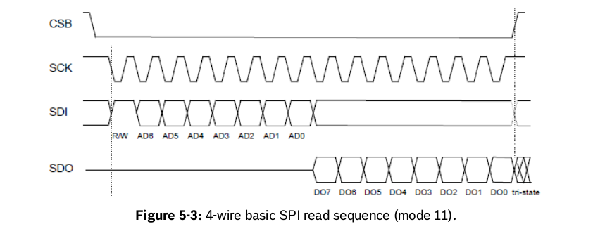
We have Accelerometer Gyroscope combo chip connected on our custom TDA2P board over McSPI3. Both Accelero and gyro have different chip select pins.

We debugged our code and found out that, when we execute following,

"mcspiHandle_gyro = GIO_create("/mcspi2", GIO_INOUT, &ioParams, &eb);"

we get below error,

" ti.sysbios.family.arm.m3.Hwi: line 143: ti.sysbios.family.arm.m3.Hwi: line 143: E_alreadyDefined: Hwi already defined: intr# 44
xdc.runtime.Error.raise: terminating execution "

Can anyone please explain where are we going wrong.

Regards,

Abhay

  • Hi Abhay,

    Can you please refer to thread: e2e.ti.com/.../2639011

    Regards,
    Rishabh

  • Hi Rishabh,

    We have gone through the thread mentioned by you. We changed the event ID of McSPI2 "CSL_INTC_EVENTID_MCSPIINT2" to 46 in file "ti_components\drivers\pdk_01_09_00_17\packages\ti\csl\soc\tda2px\cslr_soc_defines.h".

    With this change, we did not get the previous error but got an exception. Just before the exception occurs, we tried to look at the address location in CCS memory browser where the exception was coming i.e, 0x480B8110 (MCSPI_SYSCONFIG). We are able to see the value on memory browser though. We have attached the screenshot.

    Regards,

    Abhay

  • Hi Abhay,

    The original question mentions that you are using MCSPI3 and you have changed event id for MCSPI2.
    You should change for MCSPI3.

    Regards,
    Rishabh

  • Hi Rishabh,

    We are using SPI3 and in software we were getting error for CSL_INTC_EVENTID_MCSPIINT2 (with 44) value.
    So I guess for instance 3 of SPI, CSL_INTC_EVENTID_MCSPIINT2 should be applicable. Correct me if I am wrong.

    Regards,
    Abhay
  • Hi Abhay,

    Yes you are correct, MCSPI is enumerated from 0.
    Have you mapped IRQ crossbar? You also need to update HwiP_create call to use 44 interrupt number.

    Regards,
    Rishabh
  • Hi Rishabh,

    Can you please explain how and where can we do the mapping of IRQ crossbar. We already have called Hwi_create() in our code.

    We need two gpio interrupts to map GPIO5_9 and GPIO5_5 for accelero and gyro. We dont need McSPI interrupts. And we have mapped IRQ crossbar for GPIO interrupts.

    Regards,
    Abhay

  • Hi Rishabh,

    We are trying to debug GIO_Create call, we were able to debug till "Hwi_restore()" line 1103 of function "mcspiMdCreateChan()" in "/ti_components/drivers/pdk_01_09_00_17/packages/ti/drv/bsp_lld/mcspi/src/bsp_mcspi.c" . It is not going beyond this function call and hangs.
    Is the changing of "CSL_INTC_EVENTID_MCSPIINT2" interrupt number from 44 to 46 creating this issue .

    Regards,
    Abhay

  • Hi Abhay,

    Are you using this particular interrupt at some other place in the code?
    Can you look for IRQ connect APIs in OSAL on how to enable crossbar.

    Regards,
    Rishabh
  • Hi Rishabh,

    We were able to fix our previous issue. But now when we execute "GIO_create()" call, we get following error ,
    "
    *ERROR* Line: 276, File: src/bsp_mcspi.c - SPIEN hold (FORCE bit) is invalid in MULTI channel mode, cannot open the channel
    ti.sysbios.io.GIO: line 253: E_createFailed: mdCreateChan returned error -10

    "

    We have enabled MULTI_CHANNEL mode because we have two chip selects(CS0 & CS1) for accelero & gyro.

    Regards,
    Abhay
  • Hi Rishabh,

    Do you have any update on this.

    Regards,
    Abhay
  • Hi Abhay,

    I have asked our MCSPI expert to help you on this.

    Regards,
    Rishabh
  • Hi Abhay,

    Are you calling GIO_create multiple times for the same MCSPI instance?

    Regards,
    Rishabh
  • Hi Rishabh,

    We are calling GIO_create only one time in our code.

    We are attaching the read write sequence of the device.Along with that we are attaching the SCLK signals.I find one issue that the SCLK we need for 16 bits,but we are getting clock for 8 bits. Is is fine according to you or this is the normal behavior.

    We are not getting the expected value when we are trying to read the device ID of Accelerometer with MCSPI_SINGLE_CHANNEL. Currently we have set "singleOrMultiChEnable = MCSPI_SINGLE_CHANNEL" as we are getting error as was explained in the earlier post. But in the final code we will need to set "singleOrMultiChEnable = MCSPI_MULTI_CHANNEL" as we have two devices over McSPI3.

    SCLK :-

    Regards,

    Abhay

  • Hi Rishabh,

    Do you have any suggestions for us. We are still stuck with this.

    Thanks,
    Abhay
  • Hi Abhay,

    What is the buf length you are passing to the GIO_submit API?
    Length should be equal to the total number of bytes in a transaction.

    McSPI is a full duplex protocol, so the in Buf and out Buff both have to be of Size Buf Length.
    And the out Buff needs to be pre filled based on the data to be sent.

    In the read sequence, You need to fill the data to be sent in the (on SDI line) at the first byte of the out Buf.
    You need to set the length to 16.
    The data read (sent on SDO line) will be present in the second byte of the in Buf after callinghte GIO_issue and GIO_reclaim.

    In the write sequence you need to fill data (R/W AD6 to AD0 from you diagram) to first byte of out Buf and (DI7 to DI0 in your diagram) in second byte of out buf and call the GIO_issue and GIO_reclaim.

    Please check if you are doing the same.

    Regards,
    Prasad
  • Hi Prasad,

    Thanks for your detailed explanation.
    Right now we are transferring a single byte (that is address of register that returns chip ID). So does this mean the total number of bytes in transmission are 2 bytes as below,
    1. 1 byte for chip ID register address
    2. 1 byte for chip ID to be read

    Correct me if I am wrong.

    Also we did not understand when do we need to call GIO_submit API because currently we are not calling this in our code.

    Regards,
    Abhay
  • Hi Abhay,

    Yes, you need to set the number of bytes to 2, the chip id will be read in the second byte of in buf .

    I mean the length passed to GIO_issue API in the previous reply.

    The transfer happens when you call the GIO_issue API.

    Regards,

    Prasad

  • Hi Prasad,

    Thanks for your reply.

    We followed the suggestion mentioned by you. Still not getting the expected data.
    Can you please check our below SPI and Buffer settings:

    #define BUFLEN 2 //(1024 * 4) /* Buffer size */ //1024
    #define BUFALIGN 128 /* Alignment of buffer for use of L2 cache */
    #define ITERATION_CNT 2 //100 /* Number of Iterations */
    #define NUM_BUFS 1 /* Num Bufs to be issued and reclaimed */ // earlier 3


    mcspiPrms.instNum = inst_num;
    mcspiPrms.hwiNumber = 7;
    mcspiPrms.enableCache = (UInt32) TRUE;
    mcspiPrms.edma3EventQueue = 0;
    mcspiPrms.enableErrIntr = (UInt32) FALSE;

    mcspiPrms.spiHWCfgData.masterOrSlave = MCSPI_COMMMODE_MASTER;
    mcspiPrms.spiHWCfgData.singleOrMultiChEnable = MCSPI_SINGLE_CHANNEL;
    mcspiPrms.spiHWCfgData.pinOpModes = MCSPI_PINOPMODE_4PIN;
    mcspiPrms.spiHWCfgData.fifoRxTrigLvl = 32;
    mcspiPrms.spiHWCfgData.fifoTxTrigLvl = 32;
    mcspiPrms.spiHWCfgData.configChfmt[0].charLength = MCSPI_LEN_16BIT;--------------As suggested by you before it was 8bit
    mcspiPrms.spiHWCfgData.configChfmt[0].multiWordAccessEnable =
    (UInt32) FALSE;
    mcspiPrms.spiHWCfgData.configChfmt[0].spiChipSelectEnablePol =
    (UInt32) FALSE;
    mcspiPrms.spiHWCfgData.configChfmt[0].clockMode = MCSPI_MODE0;
    mcspiPrms.spiHWCfgData.configChfmt[0].clockRatioExtension = 0;
    mcspiPrms.spiHWCfgData.configChfmt[0].spiWordInitDelay = MCSPI_NO_DELAY;
    mcspiPrms.spiHWCfgData.configChfmt[0].trasmitReceiveMode = MCSPI_BOTH_RXTX;
    mcspiPrms.spiHWCfgData.configChfmt[0].granularityEnable = (UInt32) TRUE;
    mcspiPrms.spiHWCfgData.configChfmt[0].busFreq = 1000000;
    mcspiPrms.spiHWCfgData.configChfmt[0].spienHighPolarity = (UInt32) FALSE;
    mcspiPrms.spiHWCfgData.configChfmt[0].slaveModeChipSelect = MCSPI_SPIEN_0; -------------------------Is this required?As TDA2P is the master
    mcspiPrms.spiHWCfgData.configChfmt[0].spiDat0Dir = MCSPI_IN;
    mcspiPrms.spiHWCfgData.configChfmt[0].spiDat1Dir = MCSPI_OUT;

    Regards,
    Abhay
  • Hi Abhay,

    The slave expects the word length as 8 from the diagram you had attached, 8bit address 8bit data.
    Then the char length should be 8bit only.

    In the GIO_issue the 2nd parameter -> dataParam.bufLen, and 3rd parameter size should be set to 2.

    Also check what is the SPI mode supported by the slave, you need to set the same in mcspiPrms.spiHWCfgData.configChfmt[0].clockMode.

    When you call the GIO_issue, the signals will be sent out, can you probe the clock, MISO and MOSI lines at this point? Check the first byte if the address expected by slave is sent out?

    Regards,
    Prasad
  • Hello,

    SPI mode supported is MODE0 and MODE3.

    While checking from CCS  GIO_issue 2nd parameter -> dataParam.bufLen, and 3rd parameter size  are equal to 2

    I am attaching the waveform for CLK vs MOSI  and CLK vs MISO respectively

    Clk vs MOSI (sending 0x80 as Tx):

    Clk vs MISO:

    Is the CLK vs MISO waveform proper??

    When we read the data in inBuf we are getting 0xFA (which is expected) but from waveform you can see that we are getting 0x0A.

    If you see the waveform, the logic level is still high after 0x0A even though there is no clock. Is this OK.

    Regards,

    Abhay

  • Hi Abhay,

    If you are getting the proper value in the inbuf then it should be fine.

    Looks like there is some issue in the probing the MISO line.

    Regards,

    Prasad

  • Hi Prasad,

    Till now we are working with McSPI loopback example of PSDK03.03 with some modifications. In this example code, we able to read what we write. And this is working only in the polled mode.
    When we enter "interrupt mode" or "DMA interrupt mode" in prompt menu, the code hangs and we do not get any data.
    Do we need to do any changes for working in interrupt mode. Please suggest.

    Thanks,
    Abhay
  • Hi Abhay,

    I think this is an issue with interrupt configuration.
    Hrishikesh also has an active thread on the similar topic.
    HWI is the interrupt line on the CPU side you want to use.
    Crossbar is used to connect an interrupt source and interrupt line.
    Interrupt source ids are mentioned in chapter "Mapping of Device Interrupts to IRQ_CROSSBAR Inputs" of TRM.
    You can choose an interrupt line from chapter "Interrupt Requests to IPU1_Cx_INTC" of TRM for IPU interrupts.
    You need to make sure the particular interrupt line has a valid value in IRQ_CROSSBAR Instance Number.
    Hope this helps.

    Regards,
    Rishabh
  • Hi Rishabh,

    We are currently using McSPI3 in polled mode.
    Our Accelero-Gyro device is generating an interrupt on GPIO5_9 line of TDA2P. By probing the interrupt line on device side we are able to see the interrupt line going high but in the software ISR is not getting invoked.

    We have done the interrupt and crossbar settings as mentioned by you in the above post.
    We have mapped IRQ_CROSSBAR_142 to interrupt line number 47 for receiving Accelerometer interrupt. Earlier we tried with interrupt line 49 but we were getting the error "E_alreadyDefined: Hwi already defined: intr# 49". So we changed the IRQ to "CTRL_CORE_IPU1_IRQ_47_48". Pin mux settings have already been checked.

    Can you suggest us what could be the reason for ISR not being invoked.

    Thanks,
    Abhay
  • Hi Abhay,

    Can you share the changes you have made.

    Regards,
    Rishabh
  • Hi Rishabh,

    Please find below changes,

    /*****************************************************************************************************/
    UInt32 recv_interrupt_num = 47;
    UInt32 gpio_pin_accel = 9

    /************************** configureGPIOInterrupt ************************/
    void configureGPIOInterrupt()
    {
    Hwi_Params hwiAttrs;
    UInt32 key;

    key = Hwi_disable();

    Hwi_Params_init(&hwiAttrs);
    hwiAttrs.maskSetting = Hwi_MaskingOption_LOWER;
    hwiAttrs.arg = NULL;

    hdlHwi = Hwi_create(recv_interrupt_num, (Hwi_FuncPtr) accelGyro_ISR, &hwiAttrs, NULL);

    Hwi_enableInterrupt(recv_interrupt_num);

    Hwi_restore(key);
    }

    /************************* mapGPIOInterrupt ***************************/
    void mapGPIOInterrupt(UInt32 base, UInt32 irq_crossbar, UInt32 mask)
    {
    UInt32 muxVal = HW_RD_REG32(base);
    muxVal &= mask;
    muxVal |= irq_crossbar;
    HW_WR_REG32(base, muxVal);
    }

    /************************* init_GPIO ***************************/
    void init_GPIO()
    {
    /*Configure interrupt controller*/
    configureGPIOInterrupt();

    mapGPIOInterrupt(SOC_CTRL_CORE_IPU1_IRQ_47_48, IRQ_CROSSBAR_142,
    SOC_CTRL_CORE_IPU1_IRQ_47_48_MASK_MSB);

    /* Enable GPIO Module
    */
    GPIOModuleEnable(gpio_base_address);

    /* GPIO for ACCL Interrupt*/
    /* Set GPIO_INT_TYPE_LEVEL_LOW on GPIO5 pin 5 */
    GPIOIntTypeSet(gpio_base_address, gpio_pin_accel, GPIO_INT_TYPE_BOTH_EDGE);

    /* Set direction GPIO Module - INPUT DIRECTION
    */
    GPIODirModeSet(gpio_base_address, gpio_pin_accel, GPIO_DIR_INPUT);

    /*Clear interrupt*/
    GPIOPinIntDisable(gpio_base_address, GPIO_INT_LINE_2, gpio_pin_accel);
    GPIOPinIntClear(gpio_base_address, GPIO_INT_LINE_2, gpio_pin_accel);

    /*Enable interrupt*/
    GPIOPinIntEnable(gpio_base_address, GPIO_INT_LINE_2, gpio_pin_accel);
    }
    /*****************************************************************************************************/

    Regards,
    Abhay
  • Hi Abhay,

    What is the value of SOC_CTRL_CORE_IPU1_IRQ_47_48_MASK_MSB and IRQ_CROSSBAR_142.
    Do you see interrupt pending bit in MCSPI registers?

    Regards,
    Rishabh
  • Hi Rishabh,

    These values are #defined as below,

    #define SOC_CTRL_CORE_IPU1_IRQ_47_48 (0x4A002810)
    #define SOC_CTRL_CORE_IPU1_IRQ_47_48_MASK_MSB (0x0000FFFF)
    #define IRQ_CROSSBAR_142 (0x8E)

    As we using GPIO interrupts, do we still need to check MCSPI interrupt pending bit.

    Regards,
    Abhay
  • Hi Rishabh,

    We found the mistake. Actually we were using the wrong Mask value. We need to use below mask value,

    #define SOC_CTRL_CORE_IPU1_IRQ_47_48_MASK_LSB (0xFFFF0000)

    With this mask value we are able to generate the interrupt and the ISR is also executing now.
    Thank you for your support.

    Regards,
    Abhay
  • Hi Abhay,

    From the description it always looked like crossbar issue. Glad that the issue is resolved now.
    Kindly use "This resolved my issue" and close the thread.

    Regards,
    Rishabh
  • Hi Rishabh,

    I will close this thread and start a new one for our previous issue of MCSPI_MULTI_CHANNEL.
    Currently I had enabled onlf SINGLE_CHANNEL (mcspiPrms.spiHWCfgData.singleOrMultiChEnable = MCSPI_SINGLE_CHANNEL) for accelerometer.
    As I need to make Gyro work I will have to use "mcspiPrms.spiHWCfgData.singleOrMultiChEnable = MCSPI_MULTI_CHANNEL" .

    Regards,
    Abhay
  • Hi Abhay,

    Thanks for the confirmation.

    Regards,
    Rishabh
  • Hi Rishabh,

    We have one doubt regarding this question of yours. Currently we calling "GIO_create" twice.
    One call is with "chanParams.chanNum = 0" & second call to GIO_create is with "chanParams.chanNum = 1".
    Is this allowed ?
    We are doing this to get two handles (acceleto & gyro). Our Accelero & gyro are on same MCSPI instance but with different chip selects (CS) & CS1).
    We have created a new thread but no one is replying on that.

    Thanks,
    Abhay
  • Hi Abhay,

    This is allowed. I will reply to your questions on other thread.

    Regards,
    Rishabh