This thread has been locked.

If you have a related question, please click the "Ask a related question" button in the top right corner. The newly created question will be automatically linked to this question.

RTOS/AM3358: ADC example issue

Part Number: AM3358

Tool/software: TI-RTOS

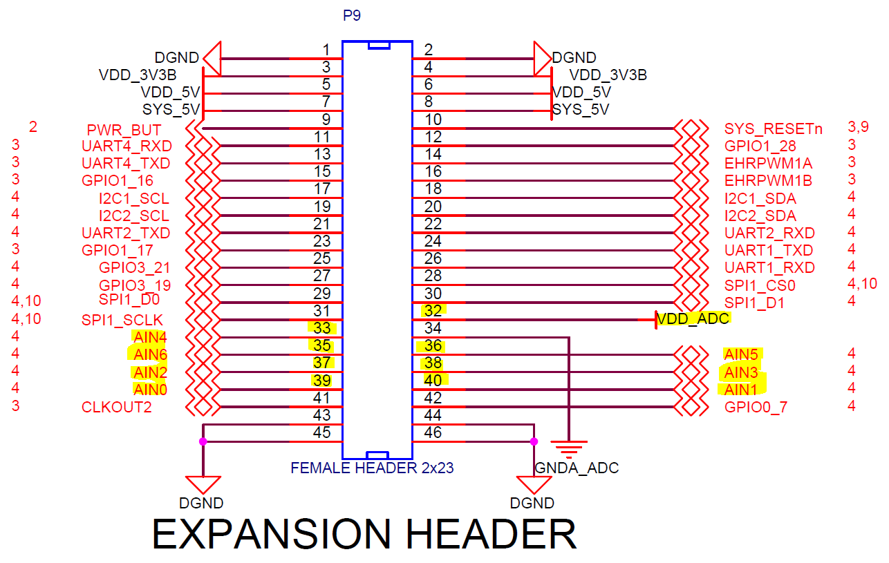
I'm developing some basic board checkout code and I need to verify the ADC peripheral. We have a custom board design based heavily off the BBB. I modified the following files:

  • beaglebone_black_config.pinmux
  • am335x_beagleboneblack_pinmux_data.c
  • bbbAM335x_pinmux.c

To add the ADC. Not sure if this was a required step.


I'm using Board_init() for initial set-up and the starterware adc_app.c and .h files. I modified the ADCAppInit() to use the ADC as general purpose vs the 4wire touch panel. (but this issue was occurring before I changed anything in the initialization file.) I don't start the Bios, as I call the check_adc() method after initializing the board and before BIOS_start().


The issue I'm having is that the ISR never gets called. Everything seems to initialize properly, but something breaks with the end of sequence interrupt and the program exits. Single stepping through I can get all the way into the:


/* Wait till the ADC processes the analog lines. */

           while(1U != gVoltMeasureAppCfg.appIntrCfg.endOfSeqIntr);


In the example main file, located here: ( C:\ti\pdk_am335x_1_0_11\packages\ti\starterware\examples\adc\volt_measure) but after I hit run, the program exits.


I've stepped through the code, and can see the registers getting set for end_of_sequence. After calling:


TSCADCEnable(pCfgAdc->instAddr, TRUE);


while single stepping, the moment that register gets set, the steps immediately clear in the STEPENABLE register.


Side Note: inside the Control_Module registers


adc_evt_capt        0x00000000        Memory Mapped        

adc_evtcapt        0000        ECAP0 event capture mux.        


The description for the adc_evtcapt register it is described as an "ECAP event capture mux"        


I'm using:

  • Code Compser Studio v7.4
  • Bios_6_52_00_12
  • Ndk_2_26_00_08
  • Pdk_am335x_1_0_1
  • xdctools_3_50_00_10_core
  • GNU v6.3.1n(linaro) compiler


Any help is greatly appreciated, thank you!

  • The RTOS team have been notified. They will respond here.
  • Matt,

    Instead of the Starterware based ADC example, are you able to use the diag ADC example located at C:\ti\pdk_am335x_1_0_11\packages\ti\board\diag\adc ?

    Lali
  • Lali,

    I will set that up give it it a try. Thank you for the suggestion.

    -Matt

  • Lali,

    After building the DIAG projects for the Beaglebone Black (BBB) using the following commands:

    cd C:\ti\pdk_am335x_1_0_11\packages

    pdksetupenv.bat

    cd C:\ti\pdk_am335x_1_0_11\packages\ti\board\diag

    gmake bbbAM335x

    The generated output does not include an ADC example for the BBB.

    It looks like I can use the adc_test.c file, located here: "C:\ti\pdk_am335x_1_0_11\packages\ti\board\diag\adc\src" and pull that into my project as I did with the starterware example.

    Testing: (used an actual BBB in this case to eliminate any possible board issues)

    Using the DIAG adc_test.c file, it breaks on setting the clock divisor config. I think that's because it's missing the
    /* Clock Configuration. */
    status = PRCMModuleEnable(CHIPDB_MOD_ID_ADC0, pCfgAdc->instNum, FALSE);
    call in the DIAG example.

    Comparing the Starterware with the DIAG example, it looks like the main difference is the interrupt priority value (32 vs 16) and the use of the UART_printf statements vs. the CONSOLEUtilsPrintf along with the missing PRCMModuleEnable() call. Other than those differences they both set up a 4 wire resistive touch panel mode and a one shot interrupt callback.

    Any other suggestions? Registers to inspect / ensure they are receiving the interrupt signal?

    -Matt
  • Matt,

    Did you try to add the PRCM instance to the board library and rebuild?
    status = PRCMModuleEnable(CHIPDB_MOD_ID_ADC0, 0U, 0U);

    Lali
  • Lali,

    Actually, I was experiencing earlier crashes when I added the PRCMModuleEnable(CHIPDB_MOD_ID_ADC0, 0U, 0U); to the bbbAM335x.c file.

    When I removed that call and left in:

    PINMUXModuleConfig(CHIPDB_MOD_ID_ADC, 0U, NULL); in bbbAM335x_pinmux.c

    and

    #if defined(BUILDCFG_MOD_ADC)

    static pinmuxPerCfg_t gAdc0PinCfg[] =
    {
    {PINMUX_INVALID_PIN}
    };

    static pinmuxModuleCfg_t gAdcPinCfg[] =
    {
    {0, TRUE, gAdc0PinCfg},
    {CHIPDB_INVALID_INSTANCE_NUM}
    };

    #endif /* if defined(BUILDCFG_MOD_ADC) */

    #...

    #if defined(BUILDCFG_MOD_ADC)
    {CHIPDB_MOD_ID_ADC, gAdcPinCfg},
    #endif /* if defined(BUILDCFG_MOD_ADC) */

    in am335x_beagleboneblack_pinmux_data.c

    After rebuilding the pdk with PRCMModuleEnable() removed, my program no longer crashed immediately. It is fairly confusing as to why that was happening, but it did. The starterware example uses that call in the init portion without issues.

    Since I've stripped this project down to the bare bones, UART, and GPIO led blink (this never actually gets called), I can try adding the PRCMModuleEnable() back in to bbbAM335x_pinmux.c and rebuild the pdk. I've done this twice already with different versions of my checkout code without success.

    -Matt
  • Lali,

    Rebuilding the pdk question.  The files generated by the PinMuxTool Version: 4.0.1522, generates the am335x_pinmux_data.c file and creates the following lines for the ADC:

    #if defined(BUILDCFG_MOD_ADC)
    {CHIPDB_MOD_ID_ADC, gAdcPinCfg},
    #endif /* if defined(BUILDCFG_MOD_ADC) */

    It's using the     CHIPDB_MOD_ID_ADC     #define.

    Your earlier question about enabling the clock module you sent this:

    PRCMModuleEnable(CHIPDB_MOD_ID_ADC0, 0U, 0U)

    using the  CHIPDB_MOD_ID_ADC0  #define

    C:\ti\pdk_am335x_1_0_11\packages\ti\starterware\include\am335x\chipdb_defs.s  lists several #defines


    CHIPDB_MOD_ID_ADC1 = 61U,

    CHIPDB_MOD_ID_ADC0 = 70U,

    CHIPDB_MOD_ID_ADC0_FW = 105U,

    CHIPDB_MOD_ID_ADC1_FW = 106U,

    CHIPDB_MOD_ID_ADC = 143U,

    Which define should be used, CHIPDB_MOD_ID_ADC0  or CHIPDB_MOD_ID_ADC  in the following files?

    • bbbAM335x.
    • am335x_beagleboneblack_pinmux_data.c
    • bbbAM335x_pinmux.c

    Matt

  • Matt,

    Sorry for the slow response.
    Did you use the CHIPDB_MOD_ID_ADC0 macro to see if that works? You are using ADC0 in your example.

    Also, were you able to make any more progress on this?

    Lali
  • Lali,

    Adding the ADC to the three files, 

    bbbAM335x_pinmux.c , bbbAM335x.c , am335x_beagleboneblack_pinmux_data.c and the pinmux file 

    using the CHIPDB_MOD_ID_ADC0  define

    actually breaks the UART_printf() call and never reaches the adc code. Re-removing the ADC and re-building the pdk fixes the uart issue, but of course I can no longer get past the TSCADCClkDivConfig() call because the ADC wasn't configured in the pinmux.

    -Matt

  • Matt,

    I'm actually working on trying to create an example that I can share. Will get back to you by Monday.
    Thanks for your patience.

    Lali
  • Matt,

    I have attached an example that works on the BBB based on the Starterware ADC example.

    The CCS project is attached along with a .txt of the software changes made to the pinmux files. Some of the changes are noted as "might not be needed" as I didnot go back to check if this was indeed needed.


    The only piece that needs to be enabled are the clocks and enabling the interface in Software. Hopely you can follow along in the example on the libraries and other dependencies that enabled this example to be built. Some of the source files were included in the project so that breakpoints can be set and the code can be stepped through.
    The Starterware and Board libraries would need to be rebuilt once any changes are infused to ensure they are used in the application.

    In the below example, AIN0 and AIN1 are both grounded but AIN0 is showing some voltage. Some drfit in the reading, not sure why.
    Please note that you cannot put more than 1.8V on the AIN pins as this will damage the SoC.
    FYI, Pin 32 on header P9 produces 1.8V (VDD_ADC)

    Hope this helps.

    Lali

    /cfs-file/__key/communityserver-discussions-components-files/791/BBB_5F00_ADC_5F00_PDK_5F00_example.zip

    /cfs-file/__key/communityserver-discussions-components-files/791/BBB_5F00_ADC_5F00_PDK_5F00_softwarechanges.txt

  • Dear Lali,

    Thank You a huge leap forward for myself.

    Re offset I am getting serious problems here on AIN 1

    I use pin 32 (VDD_ADC) and 34 (GND_ADC) for reference of AIN0 and AIN1

    I then flip the AIN0 and AIN1 from VDD_ADC to GND

    Output is

    StarterWare ADC voltage measure application!!
    Voltage sensed on the AN0 line :4095 /4095
    Voltage sensed on the AN1 line :7 /4095

    StarterWare ADC voltage measure application!!
    Voltage sensed on the AN0 line :0 /4095
    Voltage sensed on the AN1 line :3991 /4095

    When you have advice please let us know.

    Warm Regards,

    MB

  • MB,

    Great to hear that you have made some progress!

    So you are expecting the below based on the flipping VDD and GND?

    StarterWare ADC voltage measure application!!
    Voltage sensed on the AN0 line :4095 /4095
    Voltage sensed on the AN1 line :0 /4095

    StarterWare ADC voltage measure application!!
    Voltage sensed on the AN0 line :0 /4095
    Voltage sensed on the AN1 line :4095 /4095

    Lali
  • Dear Lali,

    That is correct,

    Voltage sensed on the AN0 line :4095 /4095 (Connected to ADC_VCC)
    Voltage sensed on the AN1 line :0 /4095 (Connected to ADC_GND)

    and when flipped.

    Voltage sensed on the AN0 line :0 /4095 (Connected to ADC_GND)
    Voltage sensed on the AN1 line :4095 /4095 (Connected to ADC_VCC)

    Currently getting a significant offset of almost 100 as per example above.

    Warm Regards,

    MB

  • MB,

    This could be a noise issue on the board causing the strange values.
    A couple of things:

    - The ADC expects its negative input to be connected to VREFN anytime it is configure to perform a single-ended measurement. So the SEL_RFP_SWC_2_0 bit field should always be configured to a value of 1xxx when the DIFF_CNTRL bit field is configured to a value of 0.
    - Try turning off averaging to see if that helps.

    If none of these help, implement a post processing software filter that is able to detect an outlier value and discard it.
    Other than that, I don't have any more input. Thanks.

    Lali