This thread has been locked.

If you have a related question, please click the "Ask a related question" button in the top right corner. The newly created question will be automatically linked to this question.

RTOS/TDA3XEVM: CSI2 RESET_DONE

Part Number: TDA3XEVM


Tool/software: TI-RTOS

Hi,

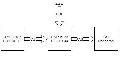
I have some adapter board which sends some video on CSI2 port and I want to connect that board with TDA3x-EVM to receive transmitted data.

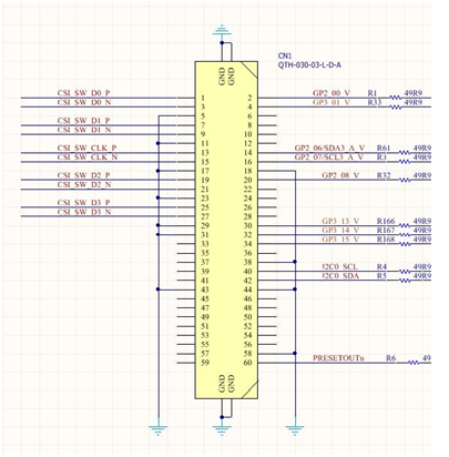
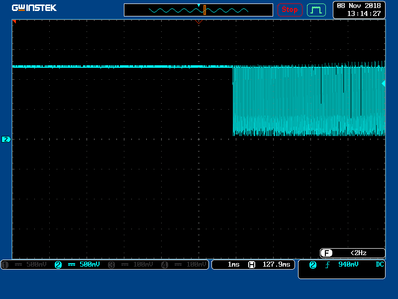
The problem I have is that I can't get any data and RESET_DONE bit is not set in CAL_CSI2_COMPLEXIO_CFG register (0x4A054213). Assuming clock lane and data lanes are correctly mapped, polarity mapping is correct and frames are being sent (checked with oscilloscope) - what could be the problem. If I remember, there is some important thing about timings - video streaming must start at specific time? These are two different boards, so I have to start them independently.

Best Regards,

Stefan.

  • Hi Stefan, Please check on the clock speed being configured, also ensure to start Capture once CSI2 source is started. Regards, Sujith
  • Hi Sujith,

    Video streaming on the sending side should be started just before you start CAL on reception side? So, is there some defined timeout for this? If this is not done quick enough, could this produce this kind of problems?

    Best Regards,
    Stefan.
  • Hi Stefan, The requirement of having CAL start after sensor is started can be explained as below 1. The receiver enables termination on the TMDS lines 2. Sensing the termination, the source (sensor) perform LP-Transitions 2.1. These LP-Transitions have definite timeout periods (based on the CSI2 Clock speed) 3. Post LP transitions both sender and receiver are sychronized and can begin high-speed transfers. In our driver implementation, when created, the lanes are configured with default values (which enables, termination). This causes sensor to perform LP-Transitions, once application provides the lanes configurations the PHY is reset and application provided configurations are applied. However, the sensor might not re-perform the LP-Transitions. The receiver waits for LP-transitions time period and conclude no-sync. Resulting no data being received. Regards, Sujith
  • Hi Sujith,

    RESET_DONE bit is now set, but still we can’t get the data on Tda3x.

    In order to help you understand our problem, I will try to explain our whole setup and I’ll be more precise about it.

    So our adapter board is custom TDA2Px SoC based board. On the other side we have TDA3xx-evm board.

    The part of adapter board setup is like this:

    This is datasheet of the CSI Connector on TDA2p side:

    CSI_SW_Dx_P/N is output of the switch. Ignore right side of the connector.

    This is datasheet of custom CSI connector which is used to properly connect our adapter board and Tda3xx-evm board:

    We configure deserializer UB960 in pattern mode RGB888 1280x720. After running everything, CAL registers on TDA3x looks like this:

    CAL_CSI2_COMPLEXIO_CFG: 6a0dca9b
    CAL_CSI2_COMPLEXIO_IRQENABLE: 0
    CAL_CSI2_SHORT_PACKET: 0
    CAL_CSI2_COMPLEXIO_IRQSTATUS: 0
    CAL_CSI2_TIMING: 4197
    CAL_CSI2_VC_IRQENABLE: 10
    CAL_CSI2_VC_IRQSTATUS: 0
    CAL_CSI2_CTX0: 2d00124
    CAL_CSI2_CTX1: 0
    CAL_CSI2_CTX2: 0
    CAL_CSI2_CTX3: 0
    CAL_CSI2_STATUS0: 1
    REG1: f002e116
    CTRL_CORE_CAMERRX_CONTROL: c019f9

    As you can see, after running everything, RESET_DONE bit is set, FRAME NUMBER increased by one and stopped.

    We also tried to connect debugger on TDA3x in order to see if vcoreCaptDmaStartCb is getting called and it’s not.
    What could be the problem here? Why did frame number increase only by one? Can we somehow check which LP State TDA3xx is in?

    We are sure that deserializer is configured properly and that the signals are getting through switch to CSI connector. Also, we have put correct line orders on TDA3x side:

    1, 2, 4, 5 - Data lanes

    3 - Clock lane

    Best Regards,

    Stefan.

  • Hi Stefan,

    I would request you to check the data-lanes mapping. With reset-done, the clock seems to be OK.
    From the snippet of schematics that's provided, we really cannot comment.

    Regards,
    Sujith
  • Hi Sujith,

    Ok, we succeeded to capture data from UB960 on TDA3x side, there were some HW issues with CSI connector. Now we want to capture test pattern data from HDMI2CSI device (TC358743XBG) over CSI switch, but we are not able to do that. So, I have one question. These is case where data sending starts from UB960, data lanes are initially at ~0.6 V and when transaction starts all lanes jumps to 1.2 V (LP11 state):

    In second case, with TC358743XBG device, we have following:

    So, data lanes are initially at 1.2 V. Can this cause to TDA3x driver don't detect transition to LP11 state and because of that there is no data captured?

    Best Regards,

    Stefan.

  • Hi Stefan,

    In case of HDMI2CSI converter, i do not see LP transitions at all. Can you check with a differential probe?

    Regards,
    Sujith
  • Hi Stefan,

    Can we close this thread?

    Regards,
    Sujith
  • Hi Sujith,

    Yes, thread can be closed. We had wrong configuration for HDMI2CSI converter. Thank you on your time.

    Best Regards,
    Stefan.