This thread has been locked.

If you have a related question, please click the "Ask a related question" button in the top right corner. The newly created question will be automatically linked to this question.

Linux/AM5718: Codec interface issue

Part Number: AM5718
Other Parts Discussed in Thread: TAS2553, , TAS2552, TLV320AIC3111, TMDSEVM572X, DRA726, TAS2557, TAS2555

Tool/software: Linux

Hello everyone,

We have developed our board in which we use the TAS2553 ic.

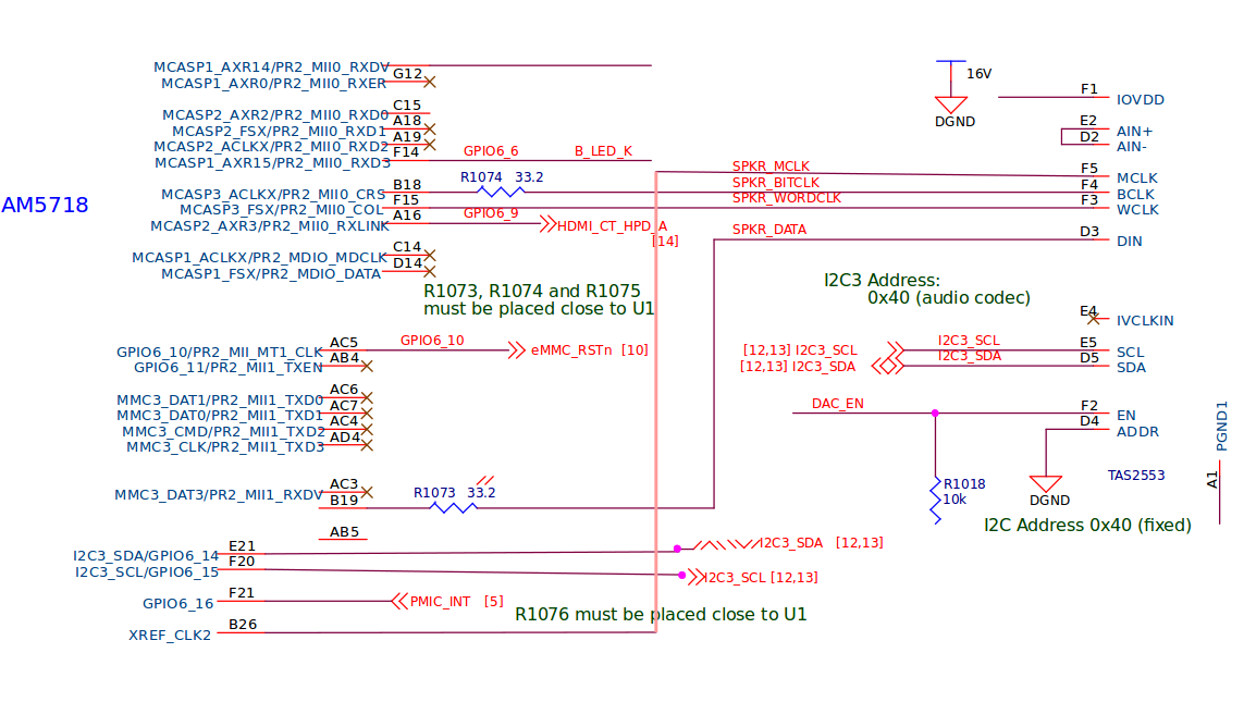
Please check the attached image for the connection of  IC with AM5718.

Also check the dtsi configurations as below.

sound0: sound0 {

status = "okay";

compatible = "simple-audio-card";

simple-audio-card,name = "tas2552";

simple-audio-card,widgets =

"Line", "Line Out",

"Line", "Line In";

simple-audio-card,routing =

"Ext Spk", "OUT";

simple-audio-card,format = "dsp_b";

sound0_master: simple-audio-card,cpu {

sound-dai = <&mcasp3>;

};

simple-audio-card,codec {

sound-dai = <&tas2552>;

};

};

&i2c3 {

status = "okay";

clock-frequency = <400000>;

tas2552: tas2552@40 {

#sound-dai-cells = <0>;

compatible = "ti,tas2552";

reg = <0x40>;   /*because we have connected ADDR to gound o.w. it will be 0x41 if it is at VDD*/

vbat-supply = <&vmain>;

iovdd-supply = <&v3_3d>;

avdd-supply = <&ldo3_reg>;

enable-gpio = <&gpio7 24 GPIO_ACTIVE_HIGH>;

status = "okay";

};

};

&mcasp3 {

#sound-dai-cells = <0>;

assigned-clocks = <&mcasp3_ahclkx_mux>;

assigned-clock-parents =<&abe_24m_fclk>;

status = "okay";

op-mode = <0>; / MCASP_IIS_MODE /

tdm-slots = <2>;

/ 4 serializers /

serial-dir = < / 0: INACTIVE, 1: TX, 2: RX /

1 2 0 0

>;

tx-num-evt = <32>;

rx-num-evt = <32>;

};

Still we are getting below error so please help us to solve this.

root@am57xx-evm:/boot# dmesg | grep tas2552
[ 2.391402] tas2552 2-0040: GPIO lookup for consumer enable
[ 2.391407] tas2552 2-0040: using device tree for GPIO lookup
[ 2.391413] of_get_named_gpiod_flags: can't parse 'enable-gpios' property of node '/ocp/i2c@48060000/tas2552@40[0]'
[ 2.391438] of_get_named_gpiod_flags: parsed 'enable-gpio' property of node '/ocp/i2c@48060000/tas2552@40[0]' - status (0)
[ 9.151096] tas2552 2-0040: Unable to sync registers 0x1-0x2. -121
[ 9.175168] tas2552 2-0040: ASoC: Failed to set DAI format: -22
[ 9.215104] asoc-simple-card sound0: tas2552-amplifier <-> 48468000.mcasp mapping ok
[ 52.170883] tas2552 2-0040: ASoC: can't set tas2552-amplifier hw params: -22

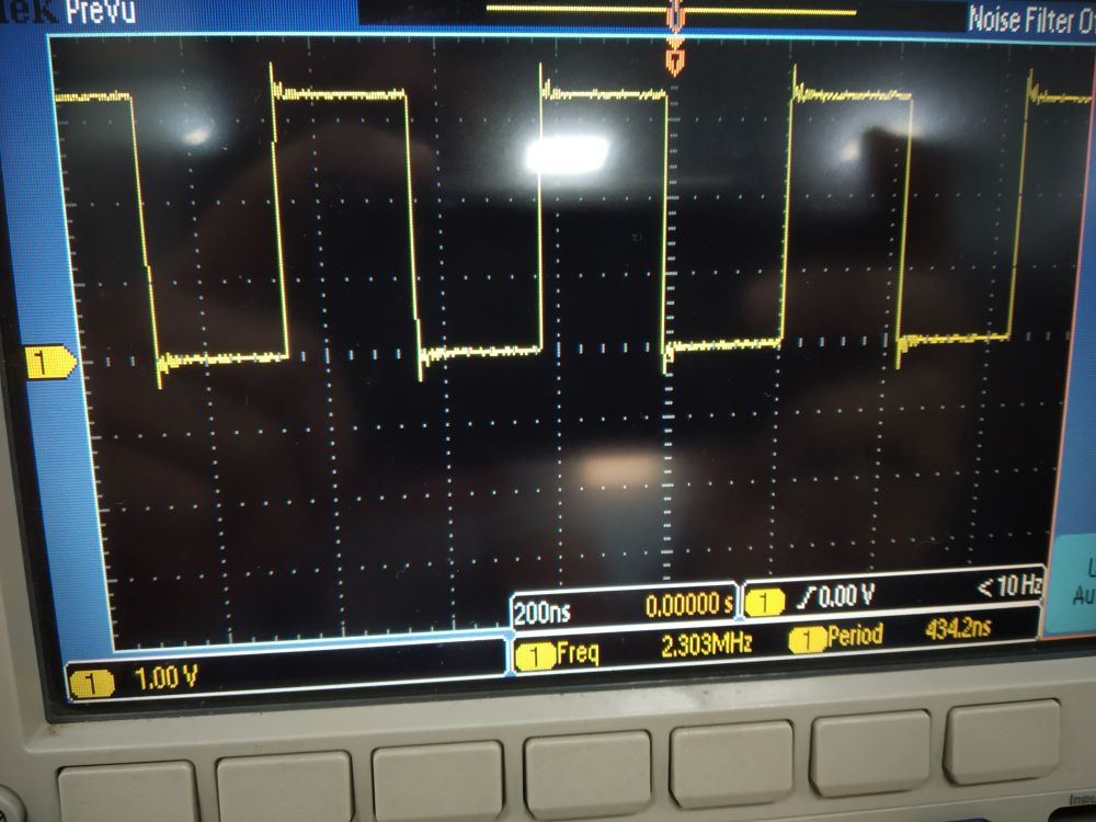
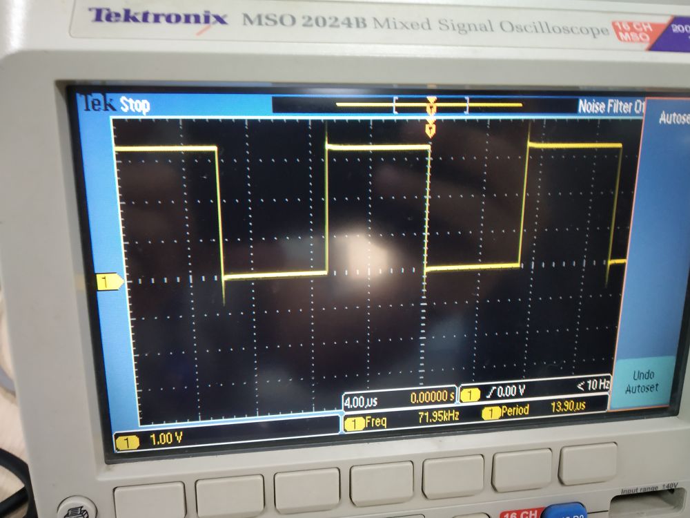
Below is the Schematic snap of connection from AM5718 to TAS2553

Thanks & Best Regards,

Nikunj Patel

  • Hi,

    Have you checked the EN signal? Is it working properly?
  • Hi Biser;
    Thanks for your reply.

    We checked the EN signal and it has 3.3 voltage. also, we checked the device with the i2cdetect tool and our tas2552(I2C Address ox40) is detected properly as below.

    root@am57xx-evm:~# i2cdetect -y -r 2
    0 1 2 3 4 5 6 7 8 9 a b c d e f
    00: -- -- -- -- -- -- -- -- -- -- -- -- --
    10: -- -- -- -- -- -- -- -- -- -- -- -- -- -- -- --
    20: -- -- -- -- -- -- -- -- -- -- -- -- -- -- -- --
    30: -- -- -- -- -- -- -- -- -- -- -- -- -- -- -- --
    40: UU -- -- -- -- -- -- -- -- -- -- -- -- -- -- --
    50: -- -- -- -- -- -- -- -- -- -- -- -- -- -- -- --
    60: -- -- -- -- -- -- -- -- -- -- -- -- -- -- -- --
    70: -- -- -- -- -- -- -- --

    Thanks & Best Regards;
    Nikunj Patel
  • Gentle reminder,

    Thanks & Best Regards;
    Nikunj Patel
  • Hi Nikunj,

    Do you use AM57x TI PSDK? If yes, which version?

    You can verify I2C connection is correct, then you can proceed with McASP connection. Besides i2cdetect, you can also test with other i2c tools like i2cdump, i2cget, i2cset. Make sure all these i2c tools are working properly and as expected.

    Check below pointers for more info regarding i2c tools:

    processors.wiki.ti.com/.../Linux_Core_I2C_User's_Guide
    processors.wiki.ti.com/.../Processor_SDK_Linux_Automotive_Display_FAQ

    Regards,
    Pavel
  • Hello Pavel;

    Do you use AM57x TI PSDK? If yes, which version?

    Ans: we are currently use the "ti-processor-sdk-linux-rt-am57xx-evm-04.01.00.06".

    Also we did not required to check the i2c because it show the perfect result. i have mentioned only for showing that the DAC EN pin is working fine.

    I need help for the TAS2553 issue so please help me as soon as possible.

    Thanks & Best Regards;
    Nikunj Patel

  • Nikunj Patel said:

    Nikunj Patel said:
    enable-gpio = <&gpio7 24 GPIO_ACTIVE_HIGH>;

    Nikunj Patel said:
    [ 2.391402] tas2552 2-0040: GPIO lookup for consumer enable
    [ 2.391407] tas2552 2-0040: using device tree for GPIO lookup
    [ 2.391413] of_get_named_gpiod_flags: can't parse 'enable-gpios' property of node '/ocp/i2c@48060000/tas2552@40[0]'
    [ 2.391438] of_get_named_gpiod_flags: parsed 'enable-gpio' property of node '/ocp/i2c@48060000/tas2552@40[0]' - status (0)

    Looks like you have some issue with this gpio enable pin, gpio7_24. This pin is E25 UART1_CTSN.gpio7_24. I do not see it in your schematic.

    "We checked the EN signal and it has 3.3 voltage." - which pin exactly you have checked?

    Have you made gpio7_24 pinmux properly? The pinmux is done in u-boot-spl, not in kernel stage.

    Regards,
    Pavel

  • Hi Pavel,

    Thanks for your reply.

    "We checked the EN signal and it has 3.3 voltage" where the "EN" is "DAC_EN" is "GPIO7_24[E25]".

    We have configured this pin in u-boot-spl as per below

    const struct pad_conf_entry core_padconf_array_essential_am571x_idk[] = {
    {UART1_CTSN, (M14 | PIN_OUTPUT)}, /* uart1_ctsn.gpio7_24 */
    }

    also, check the below configuration for the mcasp3 and MCLK pins.

    {MCASP3_ACLKX, (M0 | PIN_INPUT_PULLDOWN)}, /* mcasp3_aclkx.mcasp3_aclkx */
    {MCASP3_FSX, (M0 | PIN_INPUT_SLEW)}, /* mcasp3_fsx.mcasp3_fsx */
    {MCASP3_AXR0, (M0 | PIN_INPUT_SLEW)}, /* mcasp3_axr0.mcasp3_axr0 */
    {MCASP3_AXR1, (M0 | PIN_INPUT_SLEW)}, /* mcasp3_axr1.mcasp3_axr1 */

    {XREF_CLK2, (M9 | PIN_OUTPUT_PULLDOWN)}, /* xref_clk0.clkout2 */

    As per our measurement "DAC_EN" pin is working fine.

    We have more concern for below error.

    [ 9.151096] tas2552 2-0040: Unable to sync registers 0x1-0x2. -121
    [ 9.175168] tas2552 2-0040: ASoC: Failed to set DAI format: -22
    [ 52.170883] tas2552 2-0040: ASoC: can't set tas2552-amplifier hw params: -22

    Thanks & Best Regards;
    Nikunj Patel

  • Nikunj,

    "sound0_master: simple-audio-card,cpu"

    You are making McASP3 the master, which means McASP3 should provide the bit clock (aclkx) and frame sync (fsx). But you are making these two pins as inputs. Please check with scope aclkx/bclk and fsx/wclk pins and verify these have the correct and expected values.

    For more details regarding master/slave clock configuration, refer to the below pointers:

    www.ti.com/.../sprac09a.pdf

    linux-kernel/Documentation/devicetree/bindings/sound/simple-card.txt

    Refer also to below dts files for reference about mcasp master, codec slave configuration:

    linux-kernel/arch/arm/boot/dts/am57xx-cl-som-am57x.dts

    linux-kernel/arch/arm/boot/dts/dra72-evm-common.dtsi

    linux-kernel/arch/arm/boot/dts/dra7-evm-common.dtsi

    Regards,
    Pavel

  • Hi Pavel.

    We have modified the dtsi as below.

    &i2c3 {
    status = "okay";
    clock-frequency = <400000>;

    tas2552: tas2552@40 {
    #sound-dai-cells = <0>;
    compatible = "ti,tas2552";
    reg = <0x40>; /*because we have connected ADDR to gound o.w. it will be 0x41 if it is at VDD*/
    vbat-supply = <&vmain>;
    iovdd-supply = <&v3_3d>;
    avdd-supply = <&ldo3_reg>;
    enable-gpio = <&gpio7 24 GPIO_ACTIVE_HIGH>;
    status = "okay";
    };
    };

    sound0: sound0 {
    compatible = "simple-audio-card";
    simple-audio-card,name = "TAS2552";
    simple-audio-card,widgets =
    "Speaker", "Speaker";
    simple-audio-card,routing =
    "Speaker", "SPK";
    simple-audio-card,format = "dsp_b";
    simple-audio-card,bitclock-master = <&sound0_master>;
    simple-audio-card,frame-master = <&sound0_master>;
    simple-audio-card,bitclock-inversion;

    simple-audio-card,cpu {
    sound-dai = <&mcasp3>;
    system-clock-frequency = <12000000>;
    };

    sound0_master: simple-audio-card,codec {
    sound-dai = <&tas2552>;
    system-clock-frequency = <12000000>;
    };
    };

    &mcasp3 {
    #sound-dai-cells = <0>;
    status = "okay";

    op-mode = <0>; /* MCASP_IIS_MODE */
    tdm-slots = <2>;
    /* 4 serializers */
    serial-dir = < /* 0: INACTIVE, 1: TX, 2: RX */
    1 2 0 0
    >;
    };

    We have modified the pinmux in uboot-spl as below.

    {XREF_CLK2, (M0 | PIN_INPUT)}, /* xref_clk0
    {MCASP3_ACLKX, (M0 | PIN_INPUT_PULLDOWN)}, /* mcasp3_aclkx.mcasp3_aclkx */
    {MCASP3_FSX, (M0 | PIN_INPUT_SLEW)}, /* mcasp3_fsx.mcasp3_fsx */
    {MCASP3_AXR0, (M0 | PIN_INPUT_SLEW)}, /* mcasp3_axr0.mcasp3_axr0 */
    {MCASP3_AXR1, (M0 | PIN_INPUT_SLEW)}, /* mcasp3_axr1.mcasp3_axr1 */

    Now we are able to run .wav file using the below command and we got some audio as per wave file but still audio is not clear.
    so please check the above setting and tell us that the above setting are correct or still we are miss something?

    root@am57xx-evm:~# amixer controls
    numid=2,iface=MIXER,name='DIN source'
    numid=3,iface=MIXER,name='Input selection'
    numid=1,iface=MIXER,name='Speaker Driver Playback Volume'

    root@am57xx-evm:~# amixer cget numid=1
    numid=1,iface=MIXER,name='Speaker Driver Playback Volume'
    ; type=INTEGER,access=rw---R--,values=1,min=0,max=31,step=0
    : values=0
    | dBscale-min=-7.00dB,step=1.00dB,mute=0

    root@am57xx-evm:~# amixer cset numid=1 50%
    numid=1,iface=MIXER,name='Speaker Driver Playback Volume'
    ; type=INTEGER,access=rw---R--,values=1,min=0,max=31,step=0
    : values=16
    | dBscale-min=-7.00dB,step=1.00dB,mute=0

    root@am57xx-evm:~# aplay /usr/bin/bass.wav
    Playing WAVE '/usr/bin/bass.wav' : Signed 16 bit Little Endian, Rate 44100 Hz, Stereo

    root@am57xx-evm:~# aplay /usr/bin/ooh.wav
    Playing WAVE '/usr/bin/ooh.wav' : Signed 16 bit Little Endian, Rate 44100 Hz, Stereo


    Thanks & Best Regards;
    Nikunj patel

  • Nikunj Patel said:
    sound0_master: simple-audio-card,codec {
    sound-dai = <&tas2552>;
    system-clock-frequency = <12000000>;
    };

    From what I understand, you are trying to provide 12MHz clock signal from AM571x B26 pin (XREF_CLK2 pad) to TAS2553 MCLK F5 pin. You can check with scope that you really have this 12MHz frequency on that pin.

    In which muxmode you are using B26 pin? Note that XREF_CLK2 mode is input only. How exactly you generate 12MHz output on that B26 pin? Check also with TAS2553 support team that MCLK 12MHz clock is fine, you can use the Audio forum, link below. Check also if TAS2552 driver can be used for TAS2553 device.

    Regards,
    Pavel

  • Nikunj Patel said:
    simple-audio-card,widgets =
    "Speaker", "Speaker";
    simple-audio-card,routing =
    "Speaker", "SPK";

    Another thing you can check with Audio forum support team is if TAS2553 is supporting "Speaker".

    You can use AM437x EPOS EVM for reference (am43x-epos-evm.dts):

    simple-audio-card,widgets =
                "Speaker", "Speaker";
            simple-audio-card,routing =
                "Speaker", "SPL",
                "Speaker", "SPR";

    AM437x EPOS EVM is using tlv320aic3111 and its driver has "Speaker" and "SPL/SPR/SPK" support:

    linux-4.9.69/sound/soc/codecs/tlv320aic31xx.c

    While I do not find "Speaker" and "SPK" support in TAS2553 driver.

    Regards,
    Pavel

  • Hi Pavel,

    Thanks for your reply.

    We are using the "{XREF_CLK2, (M0 | PIN_INPUT)}, /* xref_clk0" mode and then checked with the scope and there was no any frequency on this pin.
    so please help us to select the proper mode which can be generate 12 MHz Frequency.

    bythe way we have added the "clk_id=TAS2552_PLL_CLKIN_1_8_FIXED;" line in "tas2552_set_dai_sysclk" api of tas2552 codec driver to enable the internal oscillator.

    Also, modify below changes in dts.

    sound0_master: simple-audio-card,codec {
    sound-dai = <&tas2552>;
    system-clock-frequency = <1800000>;
    };

    Then after we neasured the signals as attached

    1) MCLK

    2) BITCLK

    3) WORDCLK

    As per mesuring signal using CRO still MCLK does not proper and still sound is not proper.

    Thanks & best Regards;
    Nikunj Patel

  • Nikunj,

    You can try to set pin B26 in mode 3 (mcasp3_ahclkx). Check the below e2e thread for details:

    e2e.ti.com/.../574916

    Regards,
    Pavel
  • Hi Pavel;

    We checked your suggested link and then try to change the "davinci-mcasp.c" file but it already have added those changes as below. we are using the "4.9.59" kernel.


    static int davinci_mcasp_set_sysclk(struct snd_soc_dai *dai, int clk_id, unsigned int freq, int dir) { struct davinci_mcasp *mcasp = snd_soc_dai_get_drvdata(dai); pm_runtime_get_sync(mcasp->dev); if (dir == SND_SOC_CLOCK_IN) { switch (clk_id) { case MCASP_CLK_HCLK_AHCLK: mcasp_clr_bits(mcasp, DAVINCI_MCASP_AHCLKXCTL_REG, AHCLKXE); mcasp_clr_bits(mcasp, DAVINCI_MCASP_AHCLKRCTL_REG, AHCLKRE); mcasp_clr_bits(mcasp, DAVINCI_MCASP_PDIR_REG, AHCLKX); break; case MCASP_CLK_HCLK_AUXCLK: mcasp_set_bits(mcasp, DAVINCI_MCASP_AHCLKXCTL_REG, AHCLKXE); mcasp_set_bits(mcasp, DAVINCI_MCASP_AHCLKRCTL_REG, AHCLKRE); break; default: dev_err(mcasp->dev, "Invalid clk id: %d\n", clk_id); goto out; } } else { /* Select AUXCLK as HCLK */ printk("davinci_mcasp_set_sysclk: Select AUXCLK as HCLK \n") mcasp_set_bits(mcasp, DAVINCI_MCASP_AHCLKXCTL_REG, AHCLKXE); mcasp_set_bits(mcasp, DAVINCI_MCASP_AHCLKRCTL_REG, AHCLKRE); mcasp_set_bits(mcasp, DAVINCI_MCASP_PDIR_REG, AHCLKX); } /* * When AHCLK X/R is selected to be output it means that the HCLK is * the same clock - coming via AUXCLK. */ mcasp->sysclk_freq = freq; out: pm_runtime_put(mcasp->dev); return 0; }

    case SND_SOC_DAIFMT_CBM_CFM:
            /* codec is clock and frame master */
            mcasp_clr_bits(mcasp, DAVINCI_MCASP_ACLKXCTL_REG, ACLKXE);
            mcasp_clr_bits(mcasp, DAVINCI_MCASP_TXFMCTL_REG, AFSXE);
    
            mcasp_clr_bits(mcasp, DAVINCI_MCASP_ACLKRCTL_REG, ACLKRE);
            mcasp_clr_bits(mcasp, DAVINCI_MCASP_RXFMCTL_REG, AFSRE);
    
            mcasp_clr_bits(mcasp, DAVINCI_MCASP_PDIR_REG,
                       ACLKX | AFSX | ACLKR | AHCLKR | AFSR);
            mcasp->bclk_master = 0;
            break;

    So can you little bit help us to check that above code is ok to provide the 20 MHz frequency on B26 pin. We did not any provison to connect the OSC1 oscillator on Our board.

    Thanks & Best Regards;

    Nikunj Patel

  • Gentle reminder;

    Thanks & Best Regards;
    Nikunj Patel
  • Nikunj,

    Do you need to output 12MHz or 20MHz on B26 pin (mode mcasp3_ahclkx)? What is the current frequency (if any) you have on that pin?

    Please also provide me the below AM571x registers values:

    CTRL_CORE_PAD_XREF_CLK2
    CM_L4PER2_MCASP3_CLKCTRL
    CM_CLKSEL_PER_ABE_X1_GFCLK_MCASP_AUX

    You should get these value from user space with devmem2/omapconf tool.

    Note also that you should configure mcasp3_ahclkx pin as input, thus make it bi-directional for re-timing purpose. We have the below note in AM571x TRM:

    NOTE: For the mcaspx_aclkx, mcaspx_ahclkx and mcaspx_aclkr signals to work properly, the INPUTENABLE bit of the appropriate CTRL_CORE_PAD_x registers should be set to 0x1 because of retiming purposes.

    Then provide me the below McASP3 registers values:

    MCASP_AHCLKXCTL
    MCASP_ACLKXCTL
    PDIR

    You need to get these values using printk() statements in the mcasp linux kernel driver.

    Note also that you might have error in pinmux of pin B19. From what I understand you need that pin (mode mcasp3_axr0) to be output from AM571x device and going into pin D3 DIN of TAS2553, but you configure it as AM571x input:


    {MCASP3_AXR0, (M0 | PIN_INPUT_SLEW)}, /* mcasp3_axr0.mcasp3_axr0 */


    Regards,
    Pavel
  • Hi Pavel,

    Thanks for your reply.


    Do you need to output 12MHz or 20MHz on B26 pin (mode mcasp3_ahclkx)? What is the current frequency (if any) you have on that pin?

    Ans: We need 20Mhz on B26 Pin. We have measured using CRO as per attached image which has some garbled value.


    Please check the below value of AM571x registers values:

    CTRL_CORE_PAD_XREF_CLK2

    Ans: root@am57xx-evm:/boot# ./devmem2 0x4A00369C
    root@am57xx-evm:/boot# ./devmem2 0x4A00369C
    /dev/mem opened.
    Memory mapped at address 0xb6f78000.
    Read at address  0x4A00369C (0xb6f7869c): 0x00050003


    CM_L4PER2_MCASP3_CLKCTRL

    Ans: root@am57xx-evm:/boot# ./devmem2 0x4A009868
    /dev/mem opened.
    Memory mapped at address 0xb6f09000.
    Read at address  0x4A009868 (0xb6f09868): 0x01030000


    CM_CLKSEL_PER_ABE_X1_GFCLK_MCASP_AUX

    Ans: root@am57xx-evm:/boot# ./devmem2 0x4AE06138
    /dev/mem opened.
    Memory mapped at address 0xb6f77000.
    Read at address  0x4AE06138 (0xb6f77138): 0x00000000

    Note also that you should configure mcasp3_ahclkx pin as an input, thus make it bi-directional for re-timing purpose. We have the below note in AM571x TRM:

    NOTE: For the mcaspx_aclkx, mcaspx_ahclkx and mcaspx_aclkr signals to work properly, the INPUTENABLE bit of the appropriate CTRL_CORE_PAD_x registers should be set to 0x1 because of retiming purposes.

    Ans: Done [{XREF_CLK2, (M3 | PIN_INPUT)},    /* xref_clk0.clkout2 */]


    Then provide me the below McASP3 registers values:

    MCASP_AHCLKXCTL
    MCASP_ACLKXCTL
    PDIR

    Ans: I will update this value today.

    Note also that you might have error in pinmux of pin B19. From what I understand you need that pin (mode mcasp3_axr0) to be output from AM571x device and going into pin D3 DIN of TAS2553, but you configure it as AM571x input:

    {MCASP3_AXR0, (M0 | PIN_INPUT_SLEW)}, /* mcasp3_axr0.mcasp3_axr0 */

    Ans: We took this configuration from the begleboard-x15 board. also, we have checked with the "{MCASP3_AXR0, (M0 | PIN_OUTPUT)}," configuration but not any effect.


    Thanks & best Regards;
    Nikunj Patel

  • Nikunj,


    Nikunj Patel said:

    CM_L4PER2_MCASP3_CLKCTRL

    Ans: root@am57xx-evm:/boot# ./devmem2 0x4A009868
    /dev/mem opened.
    Memory mapped at address 0xb6f09000.
    Read at address  0x4A009868 (0xb6f09868): 0x01030000

    This value is not correct. It means your McASP3 module is disabled. This McASP3 module should be enabled in your main DTS file. Could you please attach your latest DTS file for review? You can put it in txt file and attach that file here in the e2e thread.

    Nikunj Patel said:
    Ans: I will update this value today.

    OK

    Regards,
    Pavel

  • /*
     * Copyright (C) 2015-2016 Texas Instruments Incorporated - http://www.ti.com/
     *
     * This program is free software; you can redistribute it and/or modify
     * it under the terms of the GNU General Public License version 2 as
     * published by the Free Software Foundation.
     */
    /dts-v1/;
    
    #include "dra72x.dtsi"
    #include <dt-bindings/gpio/gpio.h>
    #include <dt-bindings/interrupt-controller/irq.h>
    #include "am57xx-idk-common.dtsi"
    #include "dra72x-mmc-iodelay.dtsi"
    
    / {
    	model = "TI AM5718 IDK";
    	compatible = "ti,am5718-idk", "ti,am5718", "ti,dra7";
    
    	memory@80000000 {
    		device_type = "memory";
    		reg = <0x0 0x80000000 0x0 0x40000000>;
    	};
    
    	reserved-memory {
    		#address-cells = <2>;
    		#size-cells = <2>;
    		ranges;
    
    		ipu2_cma_pool: ipu2_cma@95800000 {
    			compatible = "shared-dma-pool";
    			reg = <0x0 0x95800000 0x0 0x3800000>;
    			reusable;
    			status = "okay";
    		};
    
    		dsp1_cma_pool: dsp1_cma@99000000 {
    			compatible = "shared-dma-pool";
    			reg = <0x0 0x99000000 0x0 0x4000000>;
    			reusable;
    			status = "okay";
    		};
    
    		ipu1_cma_pool: ipu1_cma@9d000000 {
    			compatible = "shared-dma-pool";
    			reg = <0x0 0x9d000000 0x0 0x2000000>;
    			reusable;
    			status = "okay";
    		};
    	};
    
    	/* Dual mac ethernet application node on icss2 */
    	pruss1_eth: pruss1_eth {
    		status = "okay";
    		compatible = "ti,am57-prueth";
    		pruss = <&pruss1>;
    		sram = <&ocmcram1>;
    		interrupt-parent = <&pruss1_intc>;
    
    		pruss1_emac0: ethernet-mii0 {
    			phy-handle = <&pruss1_eth0_phy>;
    			phy-mode = "mii";
    			interrupts = <20>, <22>, <23>;
    			interrupt-names = "rx", "tx", "ptp_tx";
    			/* Filled in by bootloader */
    			local-mac-address = [00 00 00 00 00 00];
    		};
    
    		pruss1_emac1: ethernet-mii1 {
    			phy-handle = <&pruss1_eth1_phy>;
    			phy-mode = "mii";
    			interrupts = <21>, <23>, <24>;
    			interrupt-names = "rx", "tx", "ptp_tx";
    			/* Filled in by bootloader */
    			local-mac-address = [00 00 00 00 00 00];
    		};
    	};
    };
    
    &mmc1 {
    	pinctrl-names = "default", "hs", "sdr12", "sdr25", "sdr50", "ddr50", "sdr104";
    	pinctrl-0 = <&mmc1_pins_default>;
    	pinctrl-1 = <&mmc1_pins_hs>;
    	pinctrl-2 = <&mmc1_pins_sdr12>;
    	pinctrl-3 = <&mmc1_pins_sdr25>;
    	pinctrl-4 = <&mmc1_pins_sdr50>;
    	pinctrl-5 = <&mmc1_pins_ddr50_rev20 &mmc1_iodelay_ddr50_conf>;
    	pinctrl-6 = <&mmc1_pins_sdr104 &mmc1_iodelay_sdr104_rev20_conf>;
    };
    
    &mmc2 {
    	pinctrl-names = "default", "hs", "ddr_1_8v";
    	pinctrl-0 = <&mmc2_pins_default>;
    	pinctrl-1 = <&mmc2_pins_hs>;
    	pinctrl-2 = <&mmc2_pins_ddr_rev20 &mmc2_iodelay_ddr_conf>;
    };
    
    &omap_dwc3_1 {
    	extcon = <&extcon_usb2>;
    };
    
    &extcon_usb2 {
    	id-gpio = <&gpio5 7 GPIO_ACTIVE_HIGH>;
    	vbus-gpio = <&gpio7 22 GPIO_ACTIVE_HIGH>;
    };
    
    &cpu0 {
    	vdd-supply = <&smps12_reg>;
    };
    
    &ov2659_1 {
    	remote-endpoint = <&vin1b>;
    };
    
    &vin1b {
    	status = "okay";
    
    	endpoint@2 {
    		slave-mode;
    		remote-endpoint = <&ov2659_1>;
    	};
    };
    
    &vip1 {
    	status = "okay";
    };
    
    &mailbox5 {
    	status = "okay";
    	mbox_ipu1_ipc3x: mbox_ipu1_ipc3x {
    		status = "disable";
    	};
    	mbox_dsp1_ipc3x: mbox_dsp1_ipc3x {
    		status = "disable";
    	};
    };
    
    &mailbox6 {
    	status = "okay";
    	mbox_ipu2_ipc3x: mbox_ipu2_ipc3x {
    		status = "disable";
    	};
    };
    
    &mmu0_dsp1 {
    	status = "okay";
    };
    
    &mmu1_dsp1 {
    	status = "okay";
    };
    
    &mmu_ipu1 {
    	status = "okay";
    };
    
    &mmu_ipu2 {
    	status = "okay";
    };
    
    &ipu2 {
    	status = "okay";
    	memory-region = <&ipu2_cma_pool>;
    	mboxes = <&mailbox6 &mbox_ipu2_ipc3x>;
    	timers = <&timer3>;
    	watchdog-timers = <&timer4>, <&timer9>;
    };
    
    &ipu1 {
    	status = "okay";
    	memory-region = <&ipu1_cma_pool>;
    	mboxes = <&mailbox5 &mbox_ipu1_ipc3x>;
    	timers = <&timer11>;
    	watchdog-timers = <&timer7>, <&timer8>;
    };
    
    &dsp1 {
    	status = "disabled";
    	memory-region = <&dsp1_cma_pool>;
    	mboxes = <&mailbox5 &mbox_dsp1_ipc3x>;
    	timers = <&timer5>;
    	watchdog-timers = <&timer10>;
    };
    
    &pcie1_rc {
    	status = "disabled";
    	gpios = <&gpio5 18 GPIO_ACTIVE_HIGH>;
    };
    
    &pcie1_ep {
    	/*
    	 * To enable PCIe EP functionality, set the status of
    	 * this node to "okay" and the status of pcie1_rc node
    	 * above to "disabled".
    	 */
    	status = "disabled";
    	gpios = <&gpio5 18 GPIO_ACTIVE_HIGH>;
    };
    
    &pruss1_mdio {
    	status = "disable";
    	reset-gpios = <&gpio5 8 GPIO_ACTIVE_LOW>;
    	reset-delay-us = <2>;   /* PHY datasheet states 1uS min */
    	pruss1_eth0_phy: ethernet-phy@0 {
    		reg = <0>;
    		interrupt-parent = <&gpio3>;
    		interrupts = <28 IRQ_TYPE_EDGE_FALLING>;
    	};
    
    	pruss1_eth1_phy: ethernet-phy@1 {
    		reg = <1>;
    		interrupt-parent = <&gpio3>;
    		interrupts = <29 IRQ_TYPE_EDGE_FALLING>;
    	};
    };
    
    &pruss2_mdio {
    	reset-gpios = <&gpio5 9 GPIO_ACTIVE_LOW>;
    	reset-delay-us = <2>;   /* PHY datasheet states 1uS min */
    };
    
    &pru1_1 {
    	ti,pruss-gp-mux-sel = <4>;	/* MII2, needed for PRUSS1_MII1 */
    };
    
    &pru2_0 {
    	ti,pruss-gp-mux-sel = <4>;	/* MII2, needed for PRUSS1_MII0 */
    };
    
    &pru2_1 {
    	ti,pruss-gp-mux-sel = <4>;	/* MII2, needed for PRUSS1_MII1 */
    };
    
    &qspi {
    	spi-max-frequency = <76800000>;
    	m25p80@0 {
    		spi-max-frequency = <76800000>;
    	};
    };


    &pwm5 {
    		status = "okay";		
    };
    &pwm6 {
    		status = "okay";		
    };
    &pwm7 {
    		status = "okay";		
    };
    &pwm8 {
    		status = "okay";		
    };
    &pwm9 {
    		status = "okay";		
    };
    &pwm10 {
    		status = "okay";
    };
    &pwm11 {
    		status = "okay";
    };
    &pwm12 {
    		status = "okay";		
    };
    
    
    &mcspi1 {
            status = "okay";
            ti,pindir-d0-out-d1-in;
    
            spidev@0{
                      compatible = "linux,spidev";
                      spi-max-frequency = <12000000>;
                      reg = <0x0>;
                      status = "okay";
            };
            
    };
    
    &mcspi3 {
            status = "okay";
            ti,pindir-d0-in-d1-out;
    
            spidev@0{
    				
    		  compatible = "linux,spidev";
                      spi-max-frequency = <12000000>;
                      reg = <0x0>;
                      status = "okay";
            };
           
    
    };
    
    #include "am57xx-evm-cmem-am571x.dtsi"
    
    #include "am57xx-evm-cmem-am571x.dtsi"
    
    #include "am57xx-evm-cmem-am571x.dtsi"
    
    /*
     * Copyright (C) 2015-2016 Texas Instruments Incorporated - http://www.ti.com/
     *
     * This program is free software; you can redistribute it and/or modify
     * it under the terms of the GNU General Public License version 2 as
     * published by the Free Software Foundation.
     */
    
    #include "am57xx-industrial-grade.dtsi"
    
    / {
    	aliases {
    		rtc0 = &tps659038_rtc;
    		rtc1 = &rtc;
    		display0 = &hdmi0;
    	};
    
    	chosen {
    		stdout-path = &uart3;
    	};
    
    	vmain: fixedregulator-vmain {
    		compatible = "regulator-fixed";
    		regulator-name = "VMAIN";
    		regulator-min-microvolt = <5000000>;
    		regulator-max-microvolt = <5000000>;
    		regulator-always-on;
    		regulator-boot-on;
    	};
    
    	v3_3d: fixedregulator-v3_3d {
    		compatible = "regulator-fixed";
    		regulator-name = "V3_3D";
    		vin-supply = <&smps9_reg>;
    		regulator-min-microvolt = <3300000>;
    		regulator-max-microvolt = <3300000>;
    		regulator-always-on;
    		regulator-boot-on;
    	};
    
    	vtt_fixed: fixedregulator-vtt {
    		/* TPS51200 */
    		compatible = "regulator-fixed";
    		regulator-name = "vtt_fixed";
    		vin-supply = <&v3_3d>;
    		regulator-min-microvolt = <3300000>;
    		regulator-max-microvolt = <3300000>;
    		regulator-always-on;
    		regulator-boot-on;
    	};
    
    	src_clk_x1: src_clk_x1 {
    		#clock-cells = <0>;
    		compatible = "fixed-clock";
    		clock-frequency = <20000000>;
    	};
    
    	leds-iio {
    		status = "disabled";
    		compatible = "gpio-leds";
    		led-out0 {
    			label = "out0";
    			gpios = <&tpic2810 0 GPIO_ACTIVE_HIGH>;
    			default-state = "off";
    		};
    
    		led-out1 {
    			label = "out1";
    			gpios = <&tpic2810 1 GPIO_ACTIVE_HIGH>;
    			default-state = "off";
    		};
    
    		led-out2 {
    			label = "out2";
    			gpios = <&tpic2810 2 GPIO_ACTIVE_HIGH>;
    			default-state = "off";
    		};
    
    		led-out3 {
    			label = "out3";
    			gpios = <&tpic2810 3 GPIO_ACTIVE_HIGH>;
    			default-state = "off";
    		};
    
    		led-out4 {
    			label = "out4";
    			gpios = <&tpic2810 4 GPIO_ACTIVE_HIGH>;
    			default-state = "off";
    		};
    
    		led-out5 {
    			label = "out5";
    			gpios = <&tpic2810 5 GPIO_ACTIVE_HIGH>;
    			default-state = "off";
    		};
    
    		led-out6 {
    			label = "out6";
    			gpios = <&tpic2810 6 GPIO_ACTIVE_HIGH>;
    			default-state = "off";
    		};
    
    		led-out7 {
    			label = "out7";
    			gpios = <&tpic2810 7 GPIO_ACTIVE_HIGH>;
    			default-state = "off";
    		};
    	};
    
    	hdmi0: connector@0 {
    		compatible = "hdmi-connector";
    		label = "hdmi";
    
    		type = "a";
    
    		port {
    			hdmi_connector_in: endpoint {
    				remote-endpoint = <&tpd12s015_out>;
    			};
    		};
    	};
    
    	tpd12s015: encoder@0 {
    		compatible = "ti,tpd12s016", "ti,tpd12s015";
    
    		gpios = <0>, /* optional CT_CP_HPD */
    			<0>, /* optional LS_OE */
    			<&gpio7 12 GPIO_ACTIVE_HIGH>;	/* HPD */
    
    		ports {
    			#address-cells = <1>;
    			#size-cells = <0>;
    
    			port@0 {
    				reg = <0>;
    
    				tpd12s015_in: endpoint@0 {
    					remote-endpoint = <&hdmi_out>;
    				};
    			};
    
    			port@1 {
    				reg = <1>;
    
    				tpd12s015_out: endpoint@0 {
    					remote-endpoint = <&hdmi_connector_in>;
    				};
    			};
    		};
    	};
    	
    	
    	sound0: sound0 {
                    compatible = "simple-audio-card";
                    simple-audio-card,name = "TAS2552";
                    simple-audio-card,widgets =
                                    "Speaker", "Speaker";
                    simple-audio-card,routing =
                                     "Speaker", "SPK";
                    simple-audio-card,format = "dsp_b";
                    simple-audio-card,bitclock-master = <&sound0_master>;
                    simple-audio-card,frame-master = <&sound0_master>;
                    simple-audio-card,bitclock-inversion;
    
                    simple-audio-card,cpu {
                            sound-dai = <&mcasp3>;
                            system-clock-frequency = <20000000>;
                    };
    
                    sound0_master: simple-audio-card,codec {
                            sound-dai = <&tas2552>;
                            system-clock-frequency = <12000000>;
                    };
            };
    	
    	src_clk_x1: src_clk_x1 {
    		#clock-cells = <0>;
    		compatible = "fixed-clock";
    		clock-frequency = <20000000>;
    	};
    
    	/* Dual-MAC Ethernet application node on PRU-ICSS2 */
    	pruss2_eth {
    		compatible = "ti,am57-prueth";
    		pruss = <&pruss2>;
    		sram = <&ocmcram1>;
    		interrupt-parent = <&pruss2_intc>;
    		/*rx-queue-size = /bits/ 16 <254 134 134 254 48>;*/ /* RED */
    		/*rx-queue-size = /bits/ 16 <194 194 194 194 48>;*/ /* EMAC */
    		/* map is lowpcp-to->hipcp where val 3=q4, 2=q3, 1=q2, 0=q1 */
    		/*pcp-rxq-map = /bits/ 8 <3 3 2 2 1 1 0 0>;*/
    
    		pruss2_emac0: ethernet-mii0 {
    			phy-handle = <&pruss2_eth0_phy>;
    			phy-mode = "mii";
    			interrupts = <20>, <22>;
    			interrupt-names = "rx", "tx";
    			/* Filled in by bootloader */
    			local-mac-address = [00 00 00 00 00 00];
    			/*tx-queue-size = /bits/ 16 <97 97 97 97 48>;*/
    		};
    
    		pruss2_emac1: ethernet-mii1 {
    			phy-handle = <&pruss2_eth1_phy>;
    			phy-mode = "mii";
    			interrupts = <21>, <23>;
    			interrupt-names = "rx", "tx";
    			/* Filled in by bootloader */
    			local-mac-address = [00 00 00 00 00 00];
    			/*tx-queue-size = /bits/ 16 <97 97 97 97 48>;*/
    		};
    	};
    };
    
    &dra7_pmx_core {
    	dcan1_pins_default: dcan1_pins_default {
    		pinctrl-single,pins = <
    			DRA7XX_CORE_IOPAD(0x37d0, PIN_OUTPUT_PULLUP | MUX_MODE0)	/* dcan1_tx */
    			DRA7XX_CORE_IOPAD(0x37d4, PIN_INPUT_PULLUP | MUX_MODE0)		/* dcan1_rx */
    		>;
    	};
    
    	dcan1_pins_sleep: dcan1_pins_sleep {
    		pinctrl-single,pins = <
    			DRA7XX_CORE_IOPAD(0x37d0, MUX_MODE15 | PULL_UP)	/* dcan1_tx.off */
    			DRA7XX_CORE_IOPAD(0x37d4, MUX_MODE15 | PULL_UP)	/* dcan1_rx.off */
    		>;
    	};
    };
    
    &i2c1 {
    	status = "okay";
    	clock-frequency = <400000>;
    
    	tps659038: tps659038@58 {
    		compatible = "ti,tps659038";
    		reg = <0x58>;
    		interrupts-extended = <&gpio6 16 IRQ_TYPE_LEVEL_HIGH
    			       &dra7_pmx_core 0x418>;
    		#interrupt-cells = <2>;
    		interrupt-controller;
    		ti,system-power-controller;
    		ti,palmas-override-powerhold;
    
    		tps659038_pmic {
    			compatible = "ti,tps659038-pmic";
    
    			smps12-in-supply = <&vmain>;
    			smps3-in-supply = <&vmain>;
    			smps45-in-supply = <&vmain>;
    			smps6-in-supply = <&vmain>;
    			smps7-in-supply = <&vmain>;
    			smps8-in-supply = <&vmain>;
    			smps9-in-supply = <&vmain>;
    			ldo1-in-supply = <&vmain>;
    			ldo2-in-supply = <&vmain>;
    			ldo3-in-supply = <&vmain>;
    			ldo4-in-supply = <&vmain>;
    			ldo9-in-supply = <&vmain>;
    			ldoln-in-supply = <&vmain>;
    			ldousb-in-supply = <&vmain>;
    			ldortc-in-supply = <&vmain>;
    
    			regulators {
    				smps12_reg: smps12 {
    					/* VDD_MPU */
    					regulator-name = "smps12";
    					regulator-min-microvolt = <850000>;
    					regulator-max-microvolt = <1250000>;
    					regulator-always-on;
    					regulator-boot-on;
    				};
    
    				smps3_reg: smps3 {
    					/* VDD_DDR EMIF1 EMIF2 */
    					regulator-name = "smps3";
    					regulator-min-microvolt = <1350000>;
    					regulator-max-microvolt = <1350000>;
    					regulator-always-on;
    					regulator-boot-on;
    				};
    
    				smps45_reg: smps45 {
    					/* VDD_DSPEVE on AM572 */
    					/* VDD_IVA + VDD_DSP on AM571 */
    					regulator-name = "smps45";
    					regulator-min-microvolt = <850000>;
    					regulator-max-microvolt = <1250000>;
    					regulator-always-on;
    					regulator-boot-on;
    				};
    
    				smps6_reg: smps6 {
    					/* VDD_GPU */
    					regulator-name = "smps6";
    					regulator-min-microvolt = <850000>;
    					regulator-max-microvolt = <1250000>;
    					regulator-always-on;
    					regulator-boot-on;
    				};
    
    				smps7_reg: smps7 {
    					/* VDD_CORE */
    					regulator-name = "smps7";
    					regulator-min-microvolt = <850000>;
    					regulator-max-microvolt = <1150000>;
    					regulator-always-on;
    					regulator-boot-on;
    				};
    
    				smps8_reg: smps8 {
    					/* 5728 - VDD_IVAHD */
    					/* 5718 - N.C. test point */
    					regulator-name = "smps8";
    				};
    
    				smps9_reg: smps9 {
    					/* VDD_3_3D */
    					regulator-name = "smps9";
    					regulator-min-microvolt = <3300000>;
    					regulator-max-microvolt = <3300000>;
    					regulator-always-on;
    					regulator-boot-on;
    				};
    
    				ldo1_reg: ldo1 {
    					/* VDDSHV8 - VSDMMC  */
    					/* NOTE: on rev 1.3a, data supply */
    					regulator-name = "ldo1";
    					regulator-min-microvolt = <1800000>;
    					regulator-max-microvolt = <3300000>;
    					regulator-boot-on;
    					regulator-always-on;
    				};
    
    				ldo2_reg: ldo2 {
    					/* VDDSH18V */
    					regulator-name = "ldo2";
    					regulator-min-microvolt = <1800000>;
    					regulator-max-microvolt = <1800000>;
    					regulator-always-on;
    					regulator-boot-on;
    				};
    
    				ldo3_reg: ldo3 {
    					/* R1.3a 572x V1_8PHY_LDO3: USB, SATA */
    					regulator-name = "ldo3";
    					regulator-min-microvolt = <1800000>;
    					regulator-max-microvolt = <1800000>;
    					regulator-always-on;
    					regulator-boot-on;
    				};
    
    				ldo4_reg: ldo4 {
    					/* R1.3a 572x V1_8PHY_LDO4: PCIE, HDMI*/
    					regulator-name = "ldo4";
    					regulator-min-microvolt = <1800000>;
    					regulator-max-microvolt = <1800000>;
    					regulator-always-on;
    					regulator-boot-on;
    				};
    
    				/* LDO5-8 unused */
    
    				ldo9_reg: ldo9 {
    					/* VDD_RTC  */
    					regulator-name = "ldo9";
    					regulator-min-microvolt = <840000>;
    					regulator-max-microvolt = <1160000>;
    					regulator-always-on;
    					regulator-boot-on;
    				};
    
    				ldoln_reg: ldoln {
    					/* VDDA_1V8_PLL */
    					regulator-name = "ldoln";
    					regulator-min-microvolt = <1800000>;
    					regulator-max-microvolt = <1800000>;
    					regulator-always-on;
    					regulator-boot-on;
    				};
    
    				ldousb_reg: ldousb {
    					/* VDDA_3V_USB: VDDA_USBHS33 */
    					regulator-name = "ldousb";
    					regulator-min-microvolt = <3300000>;
    					regulator-max-microvolt = <3300000>;
    					regulator-always-on;
    					regulator-boot-on;
    				};
    
    				ldortc_reg: ldortc {
    					/* VDDA_RTC  */
    					regulator-name = "ldortc";
    					regulator-min-microvolt = <1800000>;
    					regulator-max-microvolt = <1800000>;
    					regulator-always-on;
    					regulator-boot-on;
    				};
    
    				regen1: regen1 {
    					/* VDD_3V3_ON */
    					regulator-name = "regen1";
    					regulator-boot-on;
    					regulator-always-on;
    				};
    
    				regen2: regen2 {
    					/* Needed for PMIC internal resource */
    					regulator-name = "regen2";
    					regulator-boot-on;
    					regulator-always-on;
    				};
    			};
    		};
    
    		tps659038_rtc: tps659038_rtc {
    			compatible = "ti,palmas-rtc";
    			interrupt-parent = <&tps659038>;
    			interrupts = <8 IRQ_TYPE_EDGE_FALLING>;
    			wakeup-source;
    		};
    
    		tps659038_pwr_button: tps659038_pwr_button {
    			compatible = "ti,palmas-pwrbutton";
    			interrupt-parent = <&tps659038>;
    			interrupts = <1 IRQ_TYPE_EDGE_FALLING>;
    			wakeup-source;
    			ti,palmas-long-press-seconds = <12>;
    		};
    
    		tps659038_gpio: tps659038_gpio {
    			compatible = "ti,palmas-gpio";
    			gpio-controller;
    			#gpio-cells = <2>;
    		};
    
    		extcon_usb2: tps659038_usb {
    			compatible = "ti,palmas-usb-vid";
    			ti,enable-vbus-detection;
    			ti,enable-id-detection;
    			/* ID & VBUS GPIOs provided in board dts */
    		};
    	};
    
    	tc358778: tc358778@0e {
    		compatible = "toshiba,tc358778", "toshiba,tc358768";
    		reg = <0x0e>;
    		status = "disabled";
    
    		clocks = <&src_clk_x1>;
    		clock-names = "refclk";
    
    		ports {
    			#address-cells = <1>;
    			#size-cells = <0>;
    
    			port@0 {
    				reg = <0>;
    				tc358778_in: endpoint {
    					remote-endpoint = <&dpi_out>;
    					data-lines = <24>;
    				};
    			};
    
    			port@1 {
    				reg = <1>;
    				tc358778_out: endpoint {
    					
    				};
    			};
    		};
    	};
    
    	tpic2810: tpic2810@60 {
    		compatible = "ti,tpic2810";
    		reg = <0x60>;
    		gpio-controller;
    		#gpio-cells = <2>;
    	};
    
    	ov2659: ov2659@30 {
    		compatible = "ovti,ov2659";
    		reg = <0x30>;
    
    		clocks = <&src_clk_x1>;
    		clock-names = "xvclk";
    
    		pwrdn-gpios = <&gpio6 14 GPIO_ACTIVE_LOW>;
    
    		port {
    			ov2659_1: endpoint {
    				hsync-active = <1>;
    				vsync-active = <1>;
    				pclk-sample = <1>;
    				link-frequencies = /bits/ 64 <70000000>;
    			};
    		};
    	};
    };
    
    &mcspi1 {
    	status = "okay";
    	ti,pindir-d0-out-d1-in;
    
    	spidev@0{
                      compatible = "linux,spidev";
                      spi-max-frequency = <12000000>;
                      reg = <0x0>;
                      status = "okay";
            };
    };
    
    &mcspi3 {
    	status = "okay";
    	ti,pindir-do-in-d1-out;
    
    	spidev@0{
                      compatible = "linux,spidev";
                      spi-max-frequency = <12000000>;
                      reg = <0x0>;
                      status = "okay";
            };
    };


    &uart3 {
    	status = "okay";
    	interrupts-extended = <&crossbar_mpu GIC_SPI 69 IRQ_TYPE_LEVEL_HIGH
    			       &dra7_pmx_core 0x248>;
    };
    
    &rtc {
    	status = "okay";
    	ext-clk-src;
    };
    
    &mac {
    	status = "disabled";
    	dual_emac;
    };
    
    &cpsw_emac0 {
    	phy_id = <&davinci_mdio>, <0>;
    	phy-mode = "rgmii";
    	dual_emac_res_vlan = <1>;
    };
    
    &cpsw_emac1 {
    	phy_id = <&davinci_mdio>, <1>;
    	phy-mode = "rgmii";
    	dual_emac_res_vlan = <2>;
    };
    
    &usb2_phy1 {
    	phy-supply = <&ldousb_reg>;
    };
    
    &usb2_phy2 {
    	phy-supply = <&ldousb_reg>;
    };
    
    &usb1 {
    	dr_mode = "peripheral";
    };
    
    &usb2 {
    	dr_mode = "peripheral";
    };
    
    &mmc1 {
    	status = "okay";
    	vmmc-supply = <&v3_3d>;
    	vmmc_aux-supply = <&ldo1_reg>;
    	bus-width = <4>;
    	cd-gpios = <&gpio6 27 0>; /* gpio 219 */
    };
    
    &mmc2 {
    	status = "okay";
    	vmmc-supply = <&v3_3d>;
    	bus-width = <8>;
    	ti,non-removable;
    	max-frequency = <96000000>;
    	no-1-8-v;
    	/delete-property/ mmc-hs200-1_8v;
    };
    
    &dcan1 {
    	status = "disabled";
    	pinctrl-names = "default", "sleep", "active";
    	pinctrl-0 = <&dcan1_pins_sleep>;
    	pinctrl-1 = <&dcan1_pins_sleep>;
    	pinctrl-2 = <&dcan1_pins_default>;
    };
    
    &qspi {
    	status = "disabled";
    
    	spi-max-frequency = <76800000>;
    	m25p80@0 {
    		compatible = "s25fl256s1", "jedec,spi-nor";
    		spi-max-frequency = <76800000>;
    		reg = <0>;
    		spi-tx-bus-width = <1>;
    		spi-rx-bus-width = <4>;
    		#address-cells = <1>;
    		#size-cells = <1>;
    
    		/* MTD partition table.
    		 * The ROM checks the first four physical blocks
    		 * for a valid file to boot and the flash here is
    		 * 64KiB block size.
    		 */
    		partition@0 {
    			label = "QSPI.SPL";
    			reg = <0x00000000 0x000040000>;
    		};
    		partition@1 {
    			label = "QSPI.u-boot";
    			reg = <0x00040000 0x00100000>;
    		};
    		partition@2 {
    			label = "QSPI.u-boot-spl-os";
    			reg = <0x00140000 0x00080000>;
    		};
    		partition@3 {
    			label = "QSPI.u-boot-env";
    			reg = <0x001c0000 0x00010000>;
    		};
    		partition@4 {
    			label = "QSPI.u-boot-env.backup1";
    			reg = <0x001d0000 0x0010000>;
    		};
    		partition@5 {
    			label = "QSPI.kernel";
    			reg = <0x001e0000 0x0800000>;
    		};
    		partition@6 {
    			label = "QSPI.file-system";
    			reg = <0x009e0000 0x01620000>;
    		};
    	};
    };
    
    &hdmi {
    	status = "okay";
    	/*
    	 * XXX: Support AM572x-Rev 1.2a. this is wrong for AM571x-rev 1.3a,
    	 * AM572x-Rev1.3a - but thanks to always-on, they work.
    	 * TODO: SWITCH TO LDO4 once rev 1.2a is deprecated
    	 * (on rev 1.3a availability)
    	 */
    	vdda-supply = <&ldo4_reg>;
    
    	port {
    		hdmi_out: endpoint {
    			remote-endpoint = <&tpd12s015_in>;
    		};
    	};
    };
    
    
    &thermal_zones {
    	board_thermal: board_thermal {
    		polling-delay-passive = <1250>; /* milliseconds */
    		polling-delay = <1500>; /* milliseconds */
    
    				/* sensor       ID */
    		thermal-sensors = <&tmp102L     0>;
    
    		board_trips: trips {
    			board_alert0: board_alert {
    				temperature = <40000>; /* millicelsius */
    				hysteresis = <2000>; /* millicelsius */
    				type = "active";
    			};
    
    			board_crit: board_crit {
    				temperature = <105000>; /* millicelsius */
    				hysteresis = <0>; /* millicelsius */
    				type = "critical";
    			};
    		};
    
           };
    };
    
    
    &thermal_zones {
    	board_thermal1: board_thermal {
    		polling-delay-passive = <1250>; /* milliseconds */
    		polling-delay = <1500>; /* milliseconds */
    
    				/* sensor       ID */
    		thermal-sensors = <&tmp102R     0>;
    
    		board_trips: trips {
    			board_alert0: board_alert {
    				temperature = <30000>; /* millicelsius */
    				hysteresis = <2000>; /* millicelsius */
    				type = "active";
    			};
    
    			board_crit: board_crit {
    				temperature = <104000>; /* millicelsius */
    				hysteresis = <0>; /* millicelsius */
    				type = "critical";
    			};
    		};
    
           };
    };
    
    
    &dss {
    	status = "okay";
    
    	vdda_video-supply = <&ldoln_reg>;
    
    	ports {
    		#address-cells = <1>;
    		#size-cells = <0>;
    
    		port@0 {
    			reg = <0>;
    
    			dpi_out: endpoint {
    				remote-endpoint = <&tc358778_in>;
    				data-lines = <24>;
    			};
    		};
    	};
    };
    
    
    &bb2d {
    	status = "okay";
    };
    
    
    &mcasp3 {
    	#sound-dai-cells = <0>;
    	assigned-clocks = <&mcasp3_ahclkx_mux>;
    	assigned-clock-parents =<&abe_sys_clk_div>;
    	
    	status = "okay";
    	op-mode = <0>;	/* MCASP_IIS_MODE */
    	tdm-slots = <2>;
    	/* 4 serializers */
    	serial-dir = <	/* 0: INACTIVE, 1: TX, 2: RX */
    		1 0 0 0
    	>;
    	ti,i2s-bits = <16>;   /* support 16, 24, 32 */
    	tx-num-evt = <32>;
    	rx-num-evt = <32>;
    };


    &i2c3 {
    	status = "okay";
    	clock-frequency = <400000>;
    	
    	tas2552: tas2552@40 {
    	#sound-dai-cells = <0>;
    	compatible = "ti,tas2552";
    	reg = <0x40>;   /*because we have connected ADDR to gound o.w. it will be 0x41 if it is at VDD*/
    	vbat-supply = <&vmain>;
    	iovdd-supply = <&v3_3d>;
    	avdd-supply = <&ldo3_reg>;
    	enable-gpio = <&gpio7 24 GPIO_ACTIVE_HIGH>;
    	status = "okay";
    	};
    	
    	tmp102L: tmp102@48 {
    		compatible = "ti,tmp102";
    		reg = <0x48>;
    		interrupt-parent = <&gpio6>;
    		interrupts = <17 IRQ_TYPE_LEVEL_LOW>;
    		#thermal-sensor-cells = <1>;
    	};
    	
    	tmp102R: tmp102@49 {
    		compatible = "ti,tmp102";
    		reg = <0x49>;
    		interrupt-parent = <&gpio6>;
    		interrupts = <18 IRQ_TYPE_LEVEL_LOW>;
    		#thermal-sensor-cells = <1>;
    	};
    	
    };
    
    
    &i2c5 {
    	status = "okay";
    	clock-frequency = <400000>;
    	
    };
    
    &mailbox3 {
    	status = "okay";
    	mbox_pru1_0: mbox_pru1_0 {
    		status = "okay";
    	};
    	mbox_pru1_1: mbox_pru1_1 {
    		status = "okay";
    	};
    };
    
    &mailbox4 {
    	status = "okay";
    	mbox_pru2_0: mbox_pru2_0 {
    		status = "okay";
    	};
    	mbox_pru2_1: mbox_pru2_1 {
    		status = "okay";
    	};
    };
    
    &pruss_soc_bus1 {
    	status = "disabled";
    	
    	pruss1: pruss@4b200000 {
    		status = "okay";
    
    		pru1_0: pru@4b234000 {
    			interrupt-parent = <&pruss1_intc>;
    			interrupts = <16>, <17>;
    			interrupt-names = "vring", "kick";
    			status = "okay";
    		};
    
    		pru1_1: pru@4b238000 {
    			interrupt-parent = <&pruss1_intc>;
    			interrupts = <18>, <19>;
    			interrupt-names = "vring", "kick";
    			status = "okay";
    		};
    	};
    };
    
    &pruss_soc_bus2 {
    	status = "disabled";
    
    	pruss2: pruss@4b280000 {
    		status = "okay";
    
    		pru2_0: pru@4b2b4000 {
    			interrupt-parent = <&pruss2_intc>;
    			interrupts = <16>, <17>;
    			interrupt-names = "vring", "kick";
    			status = "okay";
    		};
    
    		pru2_1: pru@4b2b8000 {
    			interrupt-parent = <&pruss2_intc>;
    			interrupts = <18>, <19>;
    			interrupt-names = "vring", "kick";
    			status = "okay";
    		};
    	};
    };
    
    &pruss2_mdio {
    	status = "disabled";
    	pruss2_eth0_phy: ethernet-phy@0 {
    		reg = <0>;
    		interrupt-parent = <&gpio3>;
    		interrupts = <30 IRQ_TYPE_EDGE_FALLING>;
    	};
    
    	pruss2_eth1_phy: ethernet-phy@1 {
    		reg = <1>;
    		interrupt-parent = <&gpio3>;
    		interrupts = <31 IRQ_TYPE_EDGE_FALLING>;
    	};
    };


    Please find the attched both dtsi files

    Very very thanks dor quick reply.

    Thanks & Best Regards;

    Nikunj Patel

  • Nikunj,

    I see you have:

    &mcasp3 {
    #sound-dai-cells = <0>;
    assigned-clocks = <&mcasp3_ahclkx_mux>;
    assigned-clock-parents =<&abe_sys_clk_div>;

    status = "okay";
    op-mode = <0>; /* MCASP_IIS_MODE */
    tdm-slots = <2>;
    /* 4 serializers */
    serial-dir = < /* 0: INACTIVE, 1: TX, 2: RX */
    1 0 0 0
    >;
    ti,i2s-bits = <16>; /* support 16, 24, 32 */
    tx-num-evt = <32>;
    rx-num-evt = <32>;
    };


    Can you try to remove "assigned-clocks" and "assigned-clock-parents" entries and try without these two, what is the result? Do you have another value in CM_L4PER2_MCASP3_CLKCTRL register?

    Also I can not find "ti,i2s-bits" as optional DTS entry. Have you add this string "ti,i2s-bits" in McASP driver by yourself?

    linux-kernel/sound/soc/davinci/davinci-mcasp.c

    linux-kernel/Documentation/devicetree/bindings/sound/davinci-mcasp-audio.txt

    Regards,
    Pavel
  • Hi Pavel;

    I have chnaged the dtsi as below.

    &mcasp3 {

    #sound-dai-cells = <0>;

    status = "okay";

    op-mode = <0>; /* MCASP_IIS_MODE */

    tdm-slots = <2>;

    /* 4 serializers */

    serial-dir = < /* 0: INACTIVE, 1: TX, 2: RX */

    1 0 0 0

    >;

    tx-num-evt = <32>;

    rx-num-evt = <32>;

    };

    Please find the below register details

    root@am57xx-evm:/boot#  ./devmem2 0x4A00369C

    /dev/mem opened.

    Memory mapped at address 0xb6fad000.

    Read at address  0x4A00369C (0xb6fad69c): 0x00050003

    root@am57xx-evm:/boot#  ./devmem2 0x4A009868

    /dev/mem opened.

    Memory mapped at address 0xb6f03000.

    Read at address  0x4A009868 (0xb6f03868): 0x00030000

    root@am57xx-evm:/boot#  ./devmem2 0x4AE06138

    /dev/mem opened.

    Memory mapped at address 0xb6f09000.

    Read at address  0x4AE06138 (0xb6f09138): 0x00000000

    Best Regards,

    Nikunj Patel

  • Nikunj Patel said:

    root@am57xx-evm:/boot#  ./devmem2 0x4A009868

    /dev/mem opened.

    Memory mapped at address 0xb6f03000.

    Read at address  0x4A009868 (0xb6f03868): 0x00030000

    This is strange. You still have not enabled McASP3 in PRCM module. Can you try these two things:

    - remove system-clock-frequency entry in am57xx-idk-common.dtsi

    simple-audio-card,cpu {
                            sound-dai = <&mcasp3>;
                            - system-clock-frequency = <20000000>;
                    };

    - if the above do not help, update file dra7.dtsi as below

    mcasp3: mcasp@48468000 {

    ....

    - status = "disabled";

    + status = "okay";
            };

    - if the above do not help, please make sure you are building new DTB file based on latest updates of DTS files and then using this new DTB file in the board boot process.

    Regards,
    Pavel

  • Hi Pavel;

    I have changed as below in "in am57xx-idk-common.dtsi" file.

    sound0: sound0 {

                   compatible = "simple-audio-card";

                   simple-audio-card,name = "TAS2552";

                   simple-audio-card,widgets =

                                   "Speaker", "Speaker";

                   simple-audio-card,routing =

                                    "Speaker", "SPK";

                   simple-audio-card,format = "dsp_b";

                   simple-audio-card,bitclock-master = <&sound0_master>;

                   simple-audio-card,frame-master = <&sound0_master>;

                   simple-audio-card,bitclock-inversion;

                   simple-audio-card,cpu {

                           sound-dai = <&mcasp3>;

                   };

                   sound0_master: simple-audio-card,codec {

                           sound-dai = <&tas2552>;

                           system-clock-frequency = <12000000>;

                   };

           };

    Also, i have changed done below change in "dra7.dtsi" file.

    mcasp3: mcasp@48468000 {

    compatible = "ti,dra7-mcasp-audio";

    ti,hwmods = "mcasp3";

    reg = <0x48468000 0x2000>,

         <0x46000000 0x1000>;

    reg-names = "mpu","dat";

    interrupts = <GIC_SPI 151 IRQ_TYPE_LEVEL_HIGH>,

        <GIC_SPI 150 IRQ_TYPE_LEVEL_HIGH>;

    interrupt-names = "tx", "rx";

    dmas = <&edma_xbar 133 1>, <&edma_xbar 132 1>;

    dma-names = "tx", "rx";

    clocks = <&mcasp3_aux_gfclk_mux>, <&mcasp3_ahclkx_mux>;

    clock-names = "fck", "ahclkx";

    status = "okay";

    };"

    Sorry But still same result.

    root@am57xx-evm:/boot#  ./devmem2 0x4A00369C

    /dev/mem opened.

    Memory mapped at address 0xb6f15000.

    Read at address  0x4A00369C (0xb6f1569c): 0x00050003

    root@am57xx-evm:/boot# ./devmem2 0x4A009868

    /dev/mem opened.

    Memory mapped at address 0xb6f48000.

    Read at address  0x4A009868 (0xb6f48868): 0x00030000

    root@am57xx-evm:/boot#   ./devmem2 0x4AE06138

    /dev/mem opened.

    Memory mapped at address 0xb6ffc000.

    Read at address  0x4AE06138 (0xb6ffc138): 0x00000000

    Thanks & Best regards;

    Nikunj Patel

  • Nikunj,

    This is very strange. In AM572x GP EVM TMDSEVM572X, to enable mcasp3 in PRCM, only status = "okay" is used in am57xx-beagle-x15-common.dtsi file, nothing more. Thus we have CM_L4PER2_MCASP3_CLKCTRL[17:16] IDLEST = 0x0 and [1:0] MODULEMODE = 0x2

    You should check if some code is overwriting this McASP3 setting. Please make sure you are building new DTB file based on latest updates of DTS files and then using this new DTB file in the board boot process.

    Regards,
    Pavel
  • Hi Pavel;

    Please make sure you are building new DTB file based on latest updates of DTS files and then using this new DTB file in the board boot process.
    Ans: Yes Pavel I am doing much care about that.

    I have also try with the same as "am57xx-beagle-x15-common.dtsi" but there was kernel crash as below.

    &mcasp3 {
        #sound-dai-cells = <0>;
        assigned-clocks = <&mcasp3_ahclkx_mux>;
        assigned-clock-parents = <&sys_clkin2>;
        status = "okay";

        op-mode = <0>;    /* MCASP_IIS_MODE */
        tdm-slots = <2>;
        /* 4 serializers */
        serial-dir = <    /* 0: INACTIVE, 1: TX, 2: RX */
            1 2 0 0
        >;
        tx-num-evt = <32>;
        rx-num-evt = <32>;
    };

    Crash Report:

       2.244426] omap_hwmod: mcasp3: _wait_target_ready failed: -16
    [    2.250287] davinci-mcasp 48468000.mcasp: use pm_runtime_put_sync_suspend() in driver?
    [    2.271059] ------------[ cut here ]------------
    [    2.275701] WARNING: CPU: 0 PID: 1 at /home/nikunj.patel.369/workspace/new-igt/tisdk/build/arago-tmp-external-linaro-toolchain/work-shared/am57xx-evm/kernel-source/drivers/bus/omap_l3_noc.c:147 l3_interrupt_handler+0x25c/0x36c
    [    2.295857] 44000000.ocp:L3 Custom Error: MASTER MPU TARGET L4_PER2_P3 (Read): Data Access in User mode during Functional access
    [    2.307464] Modules linked in:
    [    2.310535] CPU: 0 PID: 1 Comm: swapper/0 Not tainted 4.9.59-g9a257488d4 #109
    [    2.317696] Hardware name: Generic DRA72X (Flattened Device Tree)
    [    2.323810] Backtrace: 
    [    2.326275] [<c020b29c>] (dump_backtrace) from [<c020b558>] (show_stack+0x18/0x1c)
    [    2.333874]  r7:00000009 r6:60000193 r5:00000000 r4:c1022668
    [    2.339556] [<c020b540>] (show_stack) from [<c04cd680>] (dump_stack+0x8c/0xa0)
    [    2.346807] [<c04cd5f4>] (dump_stack) from [<c022e3d4>] (__warn+0xec/0x104)
    [    2.353794]  r7:00000009 r6:c0bca41c r5:00000000 r4:ef091ae0
    [    2.359475] [<c022e2e8>] (__warn) from [<c022e42c>] (warn_slowpath_fmt+0x40/0x48)
    [    2.366986]  r9:0000001a r8:ef1cc710 r7:c0bca288 r6:00000002 r5:c0bca348 r4:c0bca3ec
    [    2.374760] [<c022e3f0>] (warn_slowpath_fmt) from [<c04fd530>] (l3_interrupt_handler+0x25c/0x36c)
    [    2.383665]  r3:ef1cc580 r2:c0bca3ec
    [    2.387250]  r4:80080003
    [    2.389793] [<c04fd2d4>] (l3_interrupt_handler) from [<c027fcf4>] (__handle_irq_event_percpu+0xb4/0x138)
    [    2.399310]  r10:c104ddee r9:ef1ca200 r8:00000017 r7:ef091c04 r6:00000000 r5:ef1ca200
    [    2.407168]  r4:ef1cca80
    [    2.409708] [<c027fc40>] (__handle_irq_event_percpu) from [<c027fd9c>] (handle_irq_event_percpu+0x24/0x60)
    [    2.419400]  r10:00000000 r9:ef090000 r8:ef006000 r7:00000000 r6:c1008bf4 r5:ef1ca200
    [    2.427257]  r4:ef1ca200
    [    2.429798] [<c027fd78>] (handle_irq_event_percpu) from [<c027fe18>] (handle_irq_event+0x40/0x64)
    [    2.438703]  r5:ef1ca260 r4:ef1ca200
    [    2.442290] [<c027fdd8>] (handle_irq_event) from [<c02834c8>] (handle_fasteoi_irq+0xc0/0x190)
    [    2.450846]  r7:00000000 r6:c1008bf4 r5:ef1ca260 r4:ef1ca200
    [    2.456527] [<c0283408>] (handle_fasteoi_irq) from [<c027ef30>] (generic_handle_irq+0x2c/0x3c)
    [    2.465170]  r7:00000000 r6:00000000 r5:00000017 r4:c0e5cde0
    [    2.470850] [<c027ef04>] (generic_handle_irq) from [<c027f4a4>] (__handle_domain_irq+0x64/0xbc)
    [    2.479582] [<c027f440>] (__handle_domain_irq) from [<c02014a0>] (gic_handle_irq+0x40/0x7c)
    [    2.487965]  r9:ef090000 r8:fa213000 r7:fa212000 r6:ef091cc0 r5:fa21200c r4:c1003424
    [    2.495737] [<c0201460>] (gic_handle_irq) from [<c020c0f8>] (__irq_svc+0x58/0x8c)
    [    2.503246] Exception stack(0xef091cc0 to 0xef091d08)
    [    2.508315] 1cc0: ef26f410 00000005 00000000 ef26f4e8 ef26f410 00000005 00000000 eeb4c510
    [    2.516524] 1ce0: 00000000 00000000 00000000 ef091d2c ef091d30 ef091d10 c0799a94 c062f9a4
    [    2.524731] 1d00: 20000113 ffffffff
    [    2.528230]  r9:ef090000 r8:00000000 r7:ef091cf4 r6:ffffffff r5:20000113 r4:c062f9a4
    [    2.536005] [<c062f980>] (__pm_runtime_idle) from [<c0799a94>] (davinci_mcasp_probe+0x9cc/0xb68)
    [    2.544824]  r7:eeb4c510 r6:00000000 r5:ef26f410 r4:eeb41a10
    [    2.550504] [<c07990c8>] (davinci_mcasp_probe) from [<c06272e0>] (platform_drv_probe+0x58/0xb8)
    [    2.559235]  r10:00000000 r9:00000000 r8:c1044fb4 r7:fffffdfb r6:c1044fb4 r5:ffffffed
    [    2.567091]  r4:ef26f410
    [    2.569633] [<c0627288>] (platform_drv_probe) from [<c0625698>] (driver_probe_device+0x230/0x2d0)
    [    2.578538]  r7:00000000 r6:00000000 r5:c1090624 r4:ef26f410
    [    2.584220] [<c0625468>] (driver_probe_device) from [<c06257f8>] (__driver_attach+0xc0/0xc4)
    [    2.592690]  r9:c0e0061c r8:000000ba r7:00000000 r6:ef26f444 r5:c1044fb4 r4:ef26f410
    [    2.600465] [<c0625738>] (__driver_attach) from [<c0623978>] (bus_for_each_dev+0x70/0xa4)
    [    2.608672]  r7:00000000 r6:c0625738 r5:c1044fb4 r4:00000000
    [    2.614353] [<c0623908>] (bus_for_each_dev) from [<c0625030>] (driver_attach+0x24/0x28)
    [    2.622386]  r6:c10362a0 r5:eeb4c480 r4:c1044fb4
    [    2.627020] [<c062500c>] (driver_attach) from [<c0624b68>] (bus_add_driver+0x108/0x214)
    [    2.635056] [<c0624a60>] (bus_add_driver) from [<c0626180>] (driver_register+0x80/0xfc)
    [    2.643089]  r7:c0e48834 r6:c0e58d54 r5:ffffe000 r4:c1044fb4
    [    2.648770] [<c0626100>] (driver_register) from [<c062723c>] (__platform_driver_register+0x48/0x50)
    [    2.657848]  r5:ffffe000 r4:c10362a0
    [    2.661436] [<c06271f4>] (__platform_driver_register) from [<c0e372f4>] (davinci_mcasp_driver_init+0x1c/0x20)
    [    2.671387]  r5:ffffe000 r4:c0e372d8
    [    2.674975] [<c0e372d8>] (davinci_mcasp_driver_init) from [<c02017bc>] (do_one_initcall+0x4c/0x178)
    [    2.684056] [<c0201770>] (do_one_initcall) from [<c0e00f64>] (kernel_init_freeable+0x1d8/0x268)
    [    2.692788]  r10:00000007 r9:c0e0061c r8:000000ba r7:c0e48834 r6:c0e58d54 r5:c1051000
    [    2.700645]  r4:c1051000
    [    2.703186] [<c0e00d8c>] (kernel_init_freeable) from [<c08ceda0>] (kernel_init+0x10/0x110)
    [    2.711482]  r10:00000000 r9:00000000 r8:00000000 r7:00000000 r6:00000000 r5:c08ced90
    [    2.719339]  r4:00000000
    [    2.721879] [<c08ced90>] (kernel_init) from [<c0207c88>] (ret_from_fork+0x14/0x2c)
    [    2.729476]  r5:c08ced90 r4:00000000
    [    2.733063] ---[ end trace f0128b3f6ea25717 ]---
    [    2.737731] Unhandled fault: asynchronous external abort (0x1211) at 0x00000000
    [    2.745066] pgd = c0003000
    [    2.747778] [00000000] *pgd=80000080004003, *pmd=00000000
    [    2.753208] Internal error: : 1211 [#1] PREEMPT SMP ARM
    [    2.758449] Modules linked in:
    [    2.761520] CPU: 0 PID: 15 Comm: kworker/0:1 Tainted: G        W       4.9.59-g9a257488d4 #109
    [    2.770163] Hardware name: Generic DRA72X (Flattened Device Tree)
    [    2.776278] Workqueue: events_freezable mmc_rescan
    [    2.781089] task: ef0b1900 task.stack: ef200000
    [    2.785636] PC is at arch_counter_get_cntpct+0x10/0x18
    [    2.790792] LR is at arch_timer_read_counter_long+0x1c/0x20
    [    2.796384] pc : [<c073e1cc>]    lr : [<c020f20c>]    psr: a0000013
    [    2.796384] sp : ef201d10  ip : ef201d20  fp : ef201d1c
    [    2.807905] r10: 00000034  r9 : 00000001  r8 : c0c2c360
    [    2.813146] r7 : 0ccccb60  r6 : 033600d5  r5 : 00001803  r4 : c1088120
    [    2.819697] r3 : c073e1bc  r2 : bea9ce20  r1 : 00000000  r0 : c1051268
    [    2.826247] Flags: NzCv  IRQs on  FIQs on  Mode SVC_32  ISA ARM  Segment user
    [    2.833408] Control: 30c5387d  Table: 80003000  DAC: fffffffd
    [    2.839173] Process kworker/0:1 (pid: 15, stack limit = 0xef200210)
    [    2.845460] Stack: (0xef201d10 to 0xef202000)
    [    2.849830] 1d00:                                     ef201d2c ef201d20 c020f20c c073e1c8
    [    2.858039] 1d20: ef201d4c ef201d30 c04cb3fc c020f1fc ef3ff000 0000018c ef201dc4 0ccccb60
    [    2.866248] 1d40: ef201d5c ef201d50 c04cb434 c04cb3b8 ef201d84 ef201d60 c071d804 c04cb418
    [    2.874456] 1d60: ef201dc4 ef3ff000 ef3ff000 00000000 00000000 00000001 ef201d9c ef201d88
    [    2.882664] 1d80: c071d954 c071d780 ef201dc4 ef201de4 ef201dbc ef201da0 c071df58 c071d868
    [    2.890872] 1da0: ef201e24 ef3ff000 00000000 ef3ff000 ef201e1c ef201dc0 c071e020 c071ded8
    [    2.899078] 1dc0: ef64aa80 00000000 ef201e24 00000000 00000000 00000000 00000000 ef201ddc
    [    2.907286] 1de0: ef201ddc 00000000 00000000 ef201dec ef201dec c071d9ac 00000000 00000000
    [    2.915494] 1e00: ef64aa80 00000c00 00000c00 ef201e97 ef201e84 ef201e20 c072905c c071dfcc
    [    2.923702] 1e20: 60000013 00000034 00000c00 00000000 00000000 00000000 00000000 00000195
    [    2.931910] 1e40: 00000000 00000000 00000000 00000000 00000000 ef201dc4 c071db48 ef3ff000
    [    2.940117] 1e60: 00061a80 ef3ff000 c0a6556c c0a65578 00000000 ef1f8180 ef201eac ef201e88
    [    2.948325] 1e80: c0729510 c0728fd0 00000000 ef201e97 00000000 ef64e000 00000000 ef3ff26c
    [    2.956533] 1ea0: ef201ed4 ef201eb0 c0720958 c07294f0 ef3ff26c ef1f8180 ef64a600 00000000
    [    2.964741] 1ec0: ef64e000 00000000 ef201f0c ef201ed8 c0244e3c c0720628 c1002d00 ef64a618
    [    2.972949] 1ee0: ef200000 ef64a600 ef1f8198 00000008 c1002d00 ef64a618 ef200000 ef1f8180
    [    2.981157] 1f00: ef201f54 ef201f10 c0245a94 c0244c6c c08d02b8 c0b9fd2c ef1f3a80 ffffe000
    [    2.989365] 1f20: ef1f8180 c104dda6 00000000 00000000 ef1f3a80 ef200000 ef1f8180 c0245a3c
    [    2.997573] 1f40: 00000000 00000000 ef201fac ef201f58 c024adb0 c0245a48 5440912e 00000000
    [    3.005780] 1f60: e28cb060 ef1f8180 00000000 00000000 ef201f70 ef201f70 00000000 00000000
    [    3.013988] 1f80: ef201f80 ef201f80 ef201fac ef1f3a80 c024acb0 00000000 00000000 00000000
    [    3.022195] 1fa0: 00000000 ef201fb0 c0207c88 c024acbc 00000000 00000000 00000000 00000000
    [    3.030403] 1fc0: 00000000 00000000 00000000 00000000 00000000 00000000 00000000 00000000
    [    3.038612] 1fe0: 00000000 00000000 00000000 00000000 00000013 00000000 9442b640 04fb2ae8
    [    3.046817] Backtrace: 
    [    3.049278] [<c073e1bc>] (arch_counter_get_cntpct) from [<c020f20c>] (arch_timer_read_counter_long+0x1c/0x20)
    [    3.059232] [<c020f1f0>] (arch_timer_read_counter_long) from [<c04cb3fc>] (__timer_delay+0x50/0x60)
    [    3.068313] [<c04cb3ac>] (__timer_delay) from [<c04cb434>] (__timer_const_udelay+0x28/0x2c)
    [    3.076696]  r7:0ccccb60 r6:ef201dc4 r5:0000018c r4:ef3ff000
    [    3.082376] [<c04cb40c>] (__timer_const_udelay) from [<c071d804>] (__mmc_start_request+0x90/0xe8)
    [    3.091283] [<c071d774>] (__mmc_start_request) from [<c071d954>] (mmc_start_request+0xf8/0x120)
    [    3.100015]  r9:00000001 r8:00000000 r7:00000000 r6:ef3ff000 r5:ef3ff000 r4:ef201dc4
    [    3.107788] [<c071d85c>] (mmc_start_request) from [<c071df58>] (mmc_wait_for_req+0x8c/0xf4)
    [    3.116169]  r5:ef201de4 r4:ef201dc4
    [    3.119757] [<c071decc>] (mmc_wait_for_req) from [<c071e020>] (mmc_wait_for_cmd+0x60/0x80)
    [    3.128051]  r7:ef3ff000 r6:00000000 r5:ef3ff000 r4:ef201e24
    [    3.133732] [<c071dfc0>] (mmc_wait_for_cmd) from [<c072905c>] (mmc_io_rw_direct_host+0x98/0x12c)
    [    3.142549]  r6:ef201e97 r5:00000c00 r4:00000c00
    [    3.147182] [<c0728fc4>] (mmc_io_rw_direct_host) from [<c0729510>] (sdio_reset+0x2c/0x64)
    [    3.155391]  r10:ef1f8180 r9:00000000 r8:c0a65578 r7:c0a6556c r6:ef3ff000 r5:00061a80
    [    3.163248]  r4:ef3ff000
    [    3.165788] [<c07294e4>] (sdio_reset) from [<c0720958>] (mmc_rescan+0x33c/0x380)
    [    3.173210]  r4:ef3ff26c
    [    3.175750] [<c072061c>] (mmc_rescan) from [<c0244e3c>] (process_one_work+0x1dc/0x3f8)
    [    3.183697]  r9:00000000 r8:ef64e000 r7:00000000 r6:ef64a600 r5:ef1f8180 r4:ef3ff26c
    [    3.191470] [<c0244c60>] (process_one_work) from [<c0245a94>] (worker_thread+0x58/0x574)
    [    3.199591]  r10:ef1f8180 r9:ef200000 r8:ef64a618 r7:c1002d00 r6:00000008 r5:ef1f8198
    [    3.207448]  r4:ef64a600
    [    3.209990] [<c0245a3c>] (worker_thread) from [<c024adb0>] (kthread+0x100/0x118)
    [    3.217414]  r10:00000000 r9:00000000 r8:c0245a3c r7:ef1f8180 r6:ef200000 r5:ef1f3a80
    [    3.225270]  r4:00000000
    [    3.227812] [<c024acb0>] (kthread) from [<c0207c88>] (ret_from_fork+0x14/0x2c)
    [    3.235061]  r8:00000000 r7:00000000 r6:00000000 r5:c024acb0 r4:ef1f3a80
    [    3.241787] Code: e1a0c00d e92dd800 e24cb004 f57ff06f (ec510f0e) 
    [    3.247903] ---[ end trace f0128b3f6ea25718 ]---
    [    3.252566] davinci-mcasp 48468000.mcasp: ERRATA i868 workaround is enabled
    [    3.260192] NET: Registered protocol family 10
    [    3.265022] Unable to handle kernel paging request at virtual address ffffffec
    [    3.272272] pgd = c0003000
    [    3.274984] [ffffffec] *pgd=80000080007003, *pmd=affb2003, *pte=00000000
    [    3.281730] Internal error: Oops: 207 [#2] PREEMPT SMP ARM
    [    3.287233] Modules linked in:
    [    3.290302] CPU: 0 PID: 15 Comm: kworker/0:1 Tainted: G      D W       4.9.59-g9a257488d4 #109
    [    3.298944] Hardware name: Generic DRA72X (Flattened Device Tree)
    [    3.305063] task: ef0b1900 task.stack: ef200000
    [    3.309610] PC is at kthread_data+0x10/0x18
    [    3.313806] LR is at wq_worker_sleeping+0x10/0xd8
    [    3.318526] pc : [<c024b7f0>]    lr : [<c0246048>]    psr: 20000193
    [    3.318526] sp : ef201ab8  ip : ef201ac8  fp : ef201ac4
    [    3.330047] r10: 00000000  r9 : ef64aa80  r8 : ef0b1d08
    [    3.335289] r7 : c1003234  r6 : c0e5da80  r5 : ef0b1900  r4 : ef64aa80
    [    3.341838] r3 : 00000000  r2 : 00000020  r1 : 00000000  r0 : ef0b1900
    [    3.348389] Flags: nzCv  IRQs off  FIQs on  Mode SVC_32  ISA ARM  Segment user
    [    3.355636] Control: 30c5387d  Table: 80003000  DAC: fffffffd
    [    3.361402] Process kworker/0:1 (pid: 15, stack limit = 0xef200210)
    [    3.367689] Stack: (0xef201ab8 to 0xef202000)
    [    3.372059] 1aa0:                                                       ef201adc ef201ac8
    [    3.380267] 1ac0: c0246048 c024b7ec ef64aa80 ef0b1900 ef201b3c ef201ae0 c08cfdac c0246044
    [    3.388475] 1ae0: ef0bcf84 ef202000 ef201b04 ef201af8 c028c9d4 c028c758 ef201b4c c02554e8
    [    3.396682] 1b00: c0230ac0 c028c9c4 c0230464 00000000 c0e592c0 ef0b1900 ef2017bc ef08c000
    [    3.404889] 1b20: ef201b58 ef0b1c80 c10077c8 c0b94ba0 ef201b4c ef201b40 c02554e8 c08cf948
    [    3.413097] 1b40: ef201b74 ef201b50 c0232310 c0255464 c073e1ce 00000000 ef201b58 ef201b58
    [    3.421304] 1b60: c022e2e4 00000001 ef201bfc ef201b78 c020b958 c0231c08 ef200210 0000000b
    [    3.429511] 1b80: c0b94ba8 00000008 bf000000 00000000 c073e1d0 60000193 6527df28 63306131
    [    3.437719] 1ba0: 20643030 64323965 30303864 34326520 30306263 35662034 30666637 28206636
    [    3.445926] 1bc0: 31356365 65306630 ef002029 ef201be8 c02154b4 c10080ec 00001211 00000007
    [    3.454134] 1be0: 00000000 ef201cc0 ef200000 00000034 ef201c0c ef201c00 c020b9dc c020b568
    [    3.462342] 1c00: ef201cbc ef201c10 c0201328 c020b9c8 00000000 ef201c20 00000007 00000000
    [    3.470550] 1c20: 00000000 00000000 00000000 c101ad18 00000000 00000001 ef201ca4 ef201c48
    [    3.478757] 1c40: c08cfbe8 c025050c ef200000 00000034 ef201c6c ef201c60 869a5d7e 00000000
    [    3.486965] 1c60: ef201c94 c08d0440 875d6d9e 00000000 c1003424 fa21200c ef201cc0 ef200000
    [    3.495172] 1c80: a0000013 ffffffff ef201cf4 c020c110 ef200000 00000034 ef201cbc c073e1cc
    [    3.503380] 1ca0: a0000013 ffffffff ef201cf4 c0c2c360 ef201d1c ef201cc0 c020c070 c0201280
    [    3.511587] 1cc0: c1051268 00000000 bea9ce20 c073e1bc c1088120 00001803 033600d5 0ccccb60
    [    3.519795] 1ce0: c0c2c360 00000001 00000034 ef201d1c ef201d20 ef201d10 c020f20c c073e1cc
    [    3.528002] 1d00: a0000013 ffffffff 00000034 00000000 ef201d2c ef201d20 c020f20c c073e1c8
    [    3.536210] 1d20: ef201d4c ef201d30 c04cb3fc c020f1fc ef3ff000 0000018c ef201dc4 0ccccb60
    [    3.544417] 1d40: ef201d5c ef201d50 c04cb434 c04cb3b8 ef201d84 ef201d60 c071d804 c04cb418
    [    3.552625] 1d60: ef201dc4 ef3ff000 ef3ff000 00000000 00000000 00000001 ef201d9c ef201d88
    [    3.560833] 1d80: c071d954 c071d780 ef201dc4 ef201de4 ef201dbc ef201da0 c071df58 c071d868
    [    3.569040] 1da0: ef201e24 ef3ff000 00000000 ef3ff000 ef201e1c ef201dc0 c071e020 c071ded8
    [    3.577248] 1dc0: ef64aa80 00000000 ef201e24 00000000 00000000 00000000 00000000 ef201ddc
    [    3.585455] 1de0: ef201ddc 00000000 00000000 ef201dec ef201dec c071d9ac 00000000 00000000
    [    3.593663] 1e00: ef64aa80 00000c00 00000c00 ef201e97 ef201e84 ef201e20 c072905c c071dfcc
    [    3.601871] 1e20: 60000013 00000034 00000c00 00000000 00000000 00000000 00000000 00000195
    [    3.610079] 1e40: 00000000 00000000 00000000 00000000 00000000 ef201dc4 c071db48 ef3ff000
    [    3.618287] 1e60: 00061a80 ef3ff000 c0a6556c c0a65578 00000000 ef1f8180 ef201eac ef201e88
    [    3.626495] 1e80: c0729510 c0728fd0 00000000 ef201e97 00000000 ef64e000 00000000 ef3ff26c
    [    3.634703] 1ea0: ef201ed4 ef201eb0 c0720958 c07294f0 ef3ff26c ef1f8180 ef64a600 00000000
    [    3.642911] 1ec0: ef64e000 00000000 ef201f0c ef201ed8 c0244e3c c0720628 c1002d00 ef64a618
    [    3.651119] 1ee0: ef200000 ef64a600 ef1f8198 00000008 c1002d00 ef64a618 ef200000 ef1f8180
    [    3.659326] 1f00: ef201f54 ef201f10 c0245a94 c0244c6c c08d02b8 c0b9fd2c ef1f3a80 ffffe000
    [    3.667533] 1f20: ef1f8180 c104dda6 00000000 00000000 ef1f3a80 ef200000 ef1f8180 c0245a3c
    [    3.675741] 1f40: 00000000 00000000 ef201fac ef201f58 c024adb0 c0245a48 5440912e 00000000
    [    3.683948] 1f60: e28cb060 ef1f8180 00000000 00000000 ef201f70 ef201f70 00000001 00010001
    [    3.692155] 1f80: ef201f80 ef201f80 ef201fac ef1f3a80 c024acb0 00000000 00000000 00000000
    [    3.700363] 1fa0: 00000000 ef201fb0 c0207c88 c024acbc 00000000 00000000 00000000 00000000
    [    3.708571] 1fc0: 00000000 00000000 00000000 00000000 00000000 00000000 00000000 00000000
    [    3.716778] 1fe0: 00000000 00000000 00000000 00000000 00000013 00000000 9442b640 04fb2ae8
    [    3.724984] Backtrace: 
    [    3.727444] [<c024b7e0>] (kthread_data) from [<c0246048>] (wq_worker_sleeping+0x10/0xd8)
    [    3.735567] [<c0246038>] (wq_worker_sleeping) from [<c08cfdac>] (__schedule+0x470/0x63c)
    [    3.743687]  r5:ef0b1900 r4:ef64aa80
    [    3.747280] [<c08cf93c>] (__schedule) from [<c02554e8>] (do_task_dead+0x90/0x94)
    [    3.754704]  r10:c0b94ba0 r9:c10077c8 r8:ef0b1c80 r7:ef201b58 r6:ef08c000 r5:ef2017bc
    [    3.762562]  r4:ef0b1900
    [    3.765103] [<c0255458>] (do_task_dead) from [<c0232310>] (do_exit+0x714/0x9f0)
    [    3.772439] [<c0231bfc>] (do_exit) from [<c020b958>] (die+0x3fc/0x460)
    [    3.778988]  r7:00000001
    [    3.781526] [<c020b55c>] (die) from [<c020b9dc>] (arm_notify_die+0x20/0x58)
    [    3.788514]  r10:00000034 r9:ef200000 r8:ef201cc0 r7:00000000 r6:00000007 r5:00001211
    [    3.796371]  r4:c10080ec
    [    3.798911] [<c020b9bc>] (arm_notify_die) from [<c0201328>] (do_DataAbort+0xb4/0xb8)
    [    3.806684] [<c0201274>] (do_DataAbort) from [<c020c070>] (__dabt_svc+0x50/0x80)
    [    3.814105] Exception stack(0xef201cc0 to 0xef201d08)
    [    3.819174] 1cc0: c1051268 00000000 bea9ce20 c073e1bc c1088120 00001803 033600d5 0ccccb60
    [    3.827383] 1ce0: c0c2c360 00000001 00000034 ef201d1c ef201d20 ef201d10 c020f20c c073e1cc
    [    3.835589] 1d00: a0000013 ffffffff
    [    3.839087]  r8:c0c2c360 r7:ef201cf4 r6:ffffffff r5:a0000013 r4:c073e1cc
    [    3.845817] [<c073e1bc>] (arch_counter_get_cntpct) from [<c020f20c>] (arch_timer_read_counter_long+0x1c/0x20)
    [    3.855771] [<c020f1f0>] (arch_timer_read_counter_long) from [<c04cb3fc>] (__timer_delay+0x50/0x60)
    [    3.864852] [<c04cb3ac>] (__timer_delay) from [<c04cb434>] (__timer_const_udelay+0x28/0x2c)
    [    3.873235]  r7:0ccccb60 r6:ef201dc4 r5:0000018c r4:ef3ff000
    [    3.878915] [<c04cb40c>] (__timer_const_udelay) from [<c071d804>] (__mmc_start_request+0x90/0xe8)
    [    3.887821] [<c071d774>] (__mmc_start_request) from [<c071d954>] (mmc_start_request+0xf8/0x120)
    [    3.896552]  r9:00000001 r8:00000000 r7:00000000 r6:ef3ff000 r5:ef3ff000 r4:ef201dc4
    [    3.904325] [<c071d85c>] (mmc_start_request) from [<c071df58>] (mmc_wait_for_req+0x8c/0xf4)
    [    3.912705]  r5:ef201de4 r4:ef201dc4
    [    3.916292] [<c071decc>] (mmc_wait_for_req) from [<c071e020>] (mmc_wait_for_cmd+0x60/0x80)
    [    3.924588]  r7:ef3ff000 r6:00000000 r5:ef3ff000 r4:ef201e24
    [    3.930267] [<c071dfc0>] (mmc_wait_for_cmd) from [<c072905c>] (mmc_io_rw_direct_host+0x98/0x12c)
    [    3.939085]  r6:ef201e97 r5:00000c00 r4:00000c00
    [    3.943717] [<c0728fc4>] (mmc_io_rw_direct_host) from [<c0729510>] (sdio_reset+0x2c/0x64)
    [    3.951926]  r10:ef1f8180 r9:00000000 r8:c0a65578 r7:c0a6556c r6:ef3ff000 r5:00061a80
    [    3.959782]  r4:ef3ff000
    [    3.962322] [<c07294e4>] (sdio_reset) from [<c0720958>] (mmc_rescan+0x33c/0x380)
    [    3.969744]  r4:ef3ff26c
    [    3.972284] [<c072061c>] (mmc_rescan) from [<c0244e3c>] (process_one_work+0x1dc/0x3f8)
    [    3.980230]  r9:00000000 r8:ef64e000 r7:00000000 r6:ef64a600 r5:ef1f8180 r4:ef3ff26c
    [    3.988002] [<c0244c60>] (process_one_work) from [<c0245a94>] (worker_thread+0x58/0x574)
    [    3.996123]  r10:ef1f8180 r9:ef200000 r8:ef64a618 r7:c1002d00 r6:00000008 r5:ef1f8198
    [    4.003980]  r4:ef64a600
    [    4.006521] [<c0245a3c>] (worker_thread) from [<c024adb0>] (kthread+0x100/0x118)
    [    4.013944]  r10:00000000 r9:00000000 r8:c0245a3c r7:ef1f8180 r6:ef200000 r5:ef1f3a80
    [    4.021801]  r4:00000000
    [    4.024343] [<c024acb0>] (kthread) from [<c0207c88>] (ret_from_fork+0x14/0x2c)
    [    4.031592]  r8:00000000 r7:00000000 r6:00000000 r5:c024acb0 r4:ef1f3a80
    [    4.038318] Code: e1a0c00d e92dd800 e24cb004 e59033d8 (e5130014) 
    [    4.044433] ---[ end trace f0128b3f6ea25719 ]---
    [    4.049064] Fixing recursive fault but reboot is needed!
    

    Thanks & Best Regards;

    Nikunj Patel

  • Hi Pavel;

    We have compulab development kit in which we checked the below register and that are almost same with us.butl it has clear sound on it's Headphone jack.

    Note: Our configuration:8 Ohm Speaker [TAS2553 Codec IC],

                compulab Development Kit configuration : 3.5mmJACK[wm8731 Codec IC]

    Testing on Compulab devlopment Kit

    [Kernel Version : 4.1.13+gitAUTOINC+8dc66170d9-r0e]


    root@cl-som-am57x:~# ./devmem2 0x4A00369C

    /dev/mem opened.

    Memory mapped at address 0xb6fcd000.

    Read at address 0x4A00369C (0xb6fcd69c): 0x0005000F

    root@cl-som-am57x:~# ./devmem2 0x4A009868

    /dev/mem opened.

    Memory mapped at address 0xb6fca000.

    Read at address 0x4A009868 (0xb6fca868): 0x04030000

    root@cl-som-am57x:~# ./devmem2 0x4AE06138

    /dev/mem opened.

    Memory mapped at address 0xb6f63000.

    Read at address 0x4AE06138 (0xb6f63138): 0x00000000

    Thanks & Best Regards;

    Nikunj Patel

  • Nikunj,

    Yes, seems that McASP module is enabled from within the kernel driver, only after executing aplay.

    Please provide me the below McASP3 registers values:

    MCASP_AHCLKXCTL
    MCASP_ACLKXCTL
    PDIR

    You need to get these values using printk() statements in the mcasp linux kernel driver.

    Regards,
    Pavel
  • Hi Pavel;

    Thanks for reply.

    Sorry but I will update you after two days due to out of  office...

    Thanks & Best regards;

    Nikunj Patel

  • Hi pavel;

    We have some modification in dtsi file as below which reference by Compulab board.

    &atl {

    status = "okay";

    assigned-clocks = <&abe_dpll_sys_clk_mux>,

     <&atl_gfclk_mux>,

     <&dpll_abe_ck>,

     <&dpll_abe_m2x2_ck>,

     <&atl_clkin2_ck>;

    assigned-clock-parents = <&sys_clkin1>, <&dpll_abe_m2_ck>;

    assigned-clock-rates = <0>, <0>, <36864000>;

    atl2 {

    bws = <4>;

    };

    };

    &mcasp3 {

    #sound-dai-cells = <0>;

    pinctrl-names = "default", "sleep";

    pinctrl-0 = <&mcasp3_pins_default>;

    pinctrl-1 = <&mcasp3_pins_sleep>;

    status = "okay";

    fck_parent = "atl_clkin2_ck";

    op-mode = <0>;          /* MCASP_IIS_MODE */

    tdm-slots = <2>;

    serial-dir = <

    1

    >;

    };

    sound0: sound0 {

    status = "okay";

                   compatible = "simple-audio-card";

                   model = "ti-tas2550";

                   simple-audio-card,name = "TAS2552";

                   simple-audio-card,format = "i2s";

                   simple-audio-card,mclk-fs = <256>;

                   simple-audio-card,widgets =

    "Speaker", "Speaker External",

    "Line", "In";

                   simple-audio-card,routing =

                                    "Speaker External", "OUT",

                                    "In", "DAC";

                   simple-audio-card,cpu {

                           sound-dai = <&mcasp3>;

                   };

                   simple-audio-card,codec {

                           sound-dai = <&tas2552>;

                           system-clock-frequency = <1800000>;

                           system-clock-id = <TAS2552_PLL_CLKIN_1_8_FIXED>;

                   };

           };

    Now We got the frequency 36.80 MHz on MCLK as per attched images. so please help us  for how to set the MCLK for 20 MHz.

    Also as per the reply by the  "Ivan Salazar"  the WCLK for "44.1ksps sampling rate" should be 44.1 Khz but why our wclk is 71.95 Khz.

    so is there required another parameter setting for that?

    BCLK=2.303 Mhz

    WCLK=71.95KHz

    MCLK=36.80MHz

    Thanks & Best Regards;

    Nikunj Patel

  • Nikunj,

    Which AM57x Compulab DTS file you refer to? I can see two AM57x Compulab DTS files but none of these is using ATL module.

    linux-kernel/arch/arm/boot/dts/am57xx-cl-som-am57x.dts
    linux-kernel/arch/arm/boot/dts/am57xx-sbc-am57x.dts

    Note that ATL (Audio Tracking Logic) module is NOT supported for AM5718 device, check DM Table 3-1. Device Comparison. Features noted as “not supported,” must not be used. Their functionality is not supported by TI for this family of devices. These features are subject to removal without notice on future device revisions. Any information regarding the unsupported features has been retained in the documentation solely for the purpose of clarifying signal names or for consistency with previous feature descriptions.

    ATL module is supported only for the automotive variant - DRA726 device


    Regards,
    Pavel
  • Hi Pavel;

    I have removed the "ATL" node and changes as below for mcasp3.

    &mcasp3 {

    #sound-dai-cells = <0>;

    pinctrl-names = "default", "sleep";

    pinctrl-0 = <&mcasp3_pins_default>;

    pinctrl-1 = <&mcasp3_pins_sleep>;

    status = "okay";

    /*fck_parent = "atl_clkin2_ck"; */

    op-mode = <0>;          /* MCASP_IIS_MODE */

    tdm-slots = <2>;

    serial-dir = <

    1 0 0 0

    >;

    tx-num-evt = <32>;

    rx-num-evt = <32>;

    };

    but whenever i try to aplay it show below error.

    aplay /usr/bin/ooh.wav -c1

    Playing WAVE '/usr/bin/ooh.wav' : Signed 16 bit Little Endian, Rate 44100 Hz, Stereo

    aplay: set_p[  193.030032] tas2552_post_event_debug1

    arams:1268: Broken configuration for this PCM: no configurations available


    Thanks & Best Reagds;

    Nikunj Patel

  • Nikunj,

    What about MCLK? Do you supply MCLK to TAS2552 codec now?

    If yes, do you have bclk and wclk clock signals generated from Codec to AM571x device?

    Regards,
    Pavel
  • Hi Pavel;

    What about MCLK? Do you supply MCLK to TAS2552 codec now?

    Ans:No.because we need lower MCLK then 22.52 MHz and still our MCLK is 36 MHz.

    If yes, do you have bclk and wclk clock signals generated from Codec to AM571x device?

    Ans: no rightnow we have changed as per previously dtsi setting to TAS2553 used as slave after Ivan reply.

    FYI:

    I have added below code in "davinci_mcasp_set_sysclk" api

        mcasp->sysclk_freq = freq;
        
        printk("davinci_mcasp_set_sysclk : mcasp->sysclk_freq=%d \n",mcasp->sysclk_freq);
        
        static void __iomem *mcasp3_base;
        uint32_t value,ui_temp;

        mcasp3_base = ioremap(0x484680B4 ,4);
        value =  __raw_readl(mcasp3_base);     
        printk(KERN_INFO "DAVINCI_MCASP_AHCLKXCTL_REG  %x\n",value);
        
        mcasp3_base = ioremap(0x484680B0 ,4);
        value =  __raw_readl(mcasp3_base);     
        printk(KERN_INFO "DAVINCI_MCASP_ACLKXCTL_REG  %x\n",value);
        
        mcasp3_base = ioremap(0x48468014 ,4);
        value =  __raw_readl(mcasp3_base);     
        printk(KERN_INFO "DAVINCI_MCASP_PDIR_REG  %x\n",value);

    Result:


    [    6.833510] davinci_mcasp_set_sysclk : mcasp->sysclk_freq=50000000
    [    6.833513] DAVINCI_MCASP_AHCLKXCTL_REG  180000
    [    6.833515] DAVINCI_MCASP_ACLKXCTL_REG  60
    [    6.833517] DAVINCI_MCASP_PDIR_REG  0

    Thanks & Best Regards;

    Nikunj Patel

  • Nikunk,

    Sorry but I am not able to understand your setup. Please clarify below questions:

    Nikunj Patel said:

    What about MCLK? Do you supply MCLK to TAS2552 codec now?

    Ans:No.because we need lower MCLK then 22.52 MHz and still our MCLK is 36 MHz.

    Do you mean that now you have clock signal supplied from AM571x mcasp3_ahclkx (pin B26) to TAS2553 MCLK? If yes, do you mean that this clock is 36MHz and you need to make it 22.52MHz?

    Nikunj Patel said:

    If yes, do you have bclk and wclk clock signals generated from Codec to AM571x device?

    Ans: no rightnow we have changed as per previously dtsi setting to TAS2553 used as slave after Ivan reply.

    Who is Ivan and where is his reply? Do you mean that now you make McASP3 master, TAS2553 slave? Please attach your latest DTS file.

    Regards,
    Pavel

  • Hi Pavel;

    What about MCLK? Do you supply MCLK to TAS2552 codec now?

    Ans: TAS2553 IC required 22.5 MHz mclk. still, we does have 22.5Mhz on B26 Pin so currently we are using the 1.8Mhz internal Oscillator[also use the PLL] of TAS2553 IC by changing the TAS2553 Configuration. and still not clear audio.

    So We have doubts of intenal oscillator so we want try to supply the MCLK frequency using B26 Pin. we can manage PLL if frequency is less than 22.5Mhz.

    If you have any live chatting support then pass details to me so i will explain more to you.

    Please check the below link for Ivan Support.

    https://e2e.ti.com/support/audio/f/6/t/733061#pi316677=2

    Thanks & Best Regards;

    Nikunj Patel

  • Nikunj Patel said:

    Ans: TAS2553 IC required 22.5 MHz mclk. still, we does have 22.5Mhz on B26 Pin so currently we are using the 1.8Mhz internal Oscillator[also use the PLL] of TAS2553 IC by changing the TAS2553 Configuration. and still not clear audio.

    So We have doubts of intenal oscillator so we want try to supply the MCLK frequency using B26 Pin. we can manage PLL if frequency is less than 22.5Mhz.

    From what I am able to understand, you need to supply 22.5MHz (not 12MHz, not 20MHz, not 36MHz) from AM5718 mcasp3_ahclkx (pin B26) to TAS2553 MCLK pin. Is that correct?

    Do you have any frequency on that pin B26? If yes, what is the current frequency?

    Regards,
    Pavel

  • Hi Pavel;

    Do you have any frequency on that pin B26? If yes, what is the current frequency?
    Ans: if we used the atl node than we have 36 MHz bur we removed that then we don't have any frequency on B26 Pin.

    12MHz or 20MHz frequency is oK for us. but 36 MHz is not ok.

    Thanks & Best Regards;
    Nikunj Patel

  • Nikunj,

    The value in registers PDIR and AHCLKXCTL is not correct. Please update your DTS file like below:

    simple-audio-card,cpu {
    sound-dai = <&mcasp3>;
    + system-clock-direction = "out";
    };


    Please have a try with new DTS file and report back:
    - Do you have any frequency now on pin B26? If yes, what is the frequency?
    - Attach the latest version of your DTS file
    - provide the latest values you have in the below registers, you should check these values inside the McASP driver, at the end of mcasp_start_tx() function.

    MCASP_AHCLKXCTL
    MCASP_ACLKXCTL
    PDIR

    CM_L4PER2_MCASP3_CLKCTRL
    CM_CLKSEL_PER_ABE_X1_GFCLK_MCASP_AUX


    Regards,
    Pavel
  • Hi Pavel;

    Thanks for your reply;

    I have changed as per your request please find attached dtsi file

    but we can't play wav file due to below error so we can't get the register values.

    root@am57xx-evm:~# aplay /usr/bin/piano2.wav
    Playing WAVE '/usr/bin/piano2.wav' : Signed 16 bit Little Endian, Rate 48000 Hz, Stereo
    aplay: set_params:1268: Broken configuration for this PCM: no configurations available

    so we can't measure the frequency on B26 pin.


    /*
     * Copyright (C) 2015-2016 Texas Instruments Incorporated - http://www.ti.com/
     *
     * This program is free software; you can redistribute it and/or modify
     * it under the terms of the GNU General Public License version 2 as
     * published by the Free Software Foundation.
     */
    
    #include "am57xx-industrial-grade.dtsi"
    #include <dt-bindings/sound/tas2552.h>
    
    / {
    	aliases {
    		rtc0 = &tps659038_rtc;
    		rtc1 = &rtc;
    		display0 = &hdmi0;
    	};
    
    	chosen {
    		stdout-path = &uart3;
    	};
    
    	vmain: fixedregulator-vmain {
    		compatible = "regulator-fixed";
    		regulator-name = "VMAIN";
    		regulator-min-microvolt = <5000000>;
    		regulator-max-microvolt = <5000000>;
    		regulator-always-on;
    		regulator-boot-on;
    	};
    
    	v3_3d: fixedregulator-v3_3d {
    		compatible = "regulator-fixed";
    		regulator-name = "V3_3D";
    		vin-supply = <&smps9_reg>;
    		regulator-min-microvolt = <3300000>;
    		regulator-max-microvolt = <3300000>;
    		regulator-always-on;
    		regulator-boot-on;
    	};
    
    	vtt_fixed: fixedregulator-vtt {
    		/* TPS51200 */
    		compatible = "regulator-fixed";
    		regulator-name = "vtt_fixed";
    		vin-supply = <&v3_3d>;
    		regulator-min-microvolt = <3300000>;
    		regulator-max-microvolt = <3300000>;
    		regulator-always-on;
    		regulator-boot-on;
    	};
    
    	src_clk_x1: src_clk_x1 {
    		#clock-cells = <0>;
    		compatible = "fixed-clock";
    		clock-frequency = <20000000>;
    	};
    	
    	leds {
    		compatible = "gpio-leds";
    
    		led0 {
    			label = "cl-som-am57x:green";
    			gpios = <&gpio2 5 GPIO_ACTIVE_HIGH>;
    			linux,default-trigger = "heartbeat";
    			default-state = "off";
    		};
    	};
    
    	hdmi0: connector@0 {
    		compatible = "hdmi-connector";
    		label = "hdmi";
    
    		type = "a";
    
    		port {
    			hdmi_connector_in: endpoint {
    				remote-endpoint = <&tpd12s015_out>;
    			};
    		};
    	};
    
    	tpd12s015: encoder@0 {
    		compatible = "ti,tpd12s016", "ti,tpd12s015";
    
    		gpios = <0>, /* optional CT_CP_HPD */
    			<0>, /* optional LS_OE */
    			<&gpio7 12 GPIO_ACTIVE_HIGH>;	/* HPD */
    
    		ports {
    			#address-cells = <1>;
    			#size-cells = <0>;
    
    			port@0 {
    				reg = <0>;
    
    				tpd12s015_in: endpoint@0 {
    					remote-endpoint = <&hdmi_out>;
    				};
    			};
    
    			port@1 {
    				reg = <1>;
    
    				tpd12s015_out: endpoint@0 {
    					remote-endpoint = <&hdmi_connector_in>;
    				};
    			};
    		};
    	};
    	
    	
    	sound0: sound0 {
    		status = "okay";
                    compatible = "simple-audio-card";
                    model = "ti-tas2550";
                    simple-audio-card,name = "TAS2552";
                    simple-audio-card,format = "i2s";
                    /*simple-audio-card,mclk-fs = <256>;*/
                    simple-audio-card,widgets =
    				"Speaker", "Speaker External",
    				"Line", "In";
                    simple-audio-card,routing =
                                     "Speaker External", "OUT",
                                     "In", "DAC";
                    simple-audio-card,cpu {
                            sound-dai = <&mcasp3>;
                            system-clock-direction = "out";
                    };
    
                    simple-audio-card,codec {
                            sound-dai = <&tas2552>;
                            system-clock-frequency = <1800000>; 
                            system-clock-id = <TAS2552_PLL_CLKIN_1_8_FIXED>;
                    };
            };
    	
    	src_clk_x1: src_clk_x1 {
    		#clock-cells = <0>;
    		compatible = "fixed-clock";
    		clock-frequency = <20000000>;
    	};
    
    	/* Dual-MAC Ethernet application node on PRU-ICSS2 */
    	pruss2_eth {
    		status = "disabled";
    		compatible = "ti,am57-prueth";
    		pruss = <&pruss2>;
    		sram = <&ocmcram1>;
    		interrupt-parent = <&pruss2_intc>;
    		/*rx-queue-size = /bits/ 16 <254 134 134 254 48>;*/ /* RED */
    		/*rx-queue-size = /bits/ 16 <194 194 194 194 48>;*/ /* EMAC */
    		/* map is lowpcp-to->hipcp where val 3=q4, 2=q3, 1=q2, 0=q1 */
    		/*pcp-rxq-map = /bits/ 8 <3 3 2 2 1 1 0 0>;*/
    
    		pruss2_emac0: ethernet-mii0 {
    			phy-handle = <&pruss2_eth0_phy>;
    			phy-mode = "mii";
    			interrupts = <20>, <22>;
    			interrupt-names = "rx", "tx";
    			/* Filled in by bootloader */
    			local-mac-address = [00 00 00 00 00 00];
    			/*tx-queue-size = /bits/ 16 <97 97 97 97 48>;*/
    		};
    
    		pruss2_emac1: ethernet-mii1 {
    			phy-handle = <&pruss2_eth1_phy>;
    			phy-mode = "mii";
    			interrupts = <21>, <23>;
    			interrupt-names = "rx", "tx";
    			/* Filled in by bootloader */
    			local-mac-address = [00 00 00 00 00 00];
    			/*tx-queue-size = /bits/ 16 <97 97 97 97 48>;*/
    		};
    	};
    };
    
    &dra7_pmx_core {
    	dcan1_pins_default: dcan1_pins_default {
    		pinctrl-single,pins = <
    			DRA7XX_CORE_IOPAD(0x37d0, PIN_OUTPUT_PULLUP | MUX_MODE0)	/* dcan1_tx */
    			DRA7XX_CORE_IOPAD(0x37d4, PIN_INPUT_PULLUP | MUX_MODE0)		/* dcan1_rx */
    		>;
    	};
    
    	dcan1_pins_sleep: dcan1_pins_sleep {
    		pinctrl-single,pins = <
    			DRA7XX_CORE_IOPAD(0x37d0, MUX_MODE15 | PULL_UP)	/* dcan1_tx.off */
    			DRA7XX_CORE_IOPAD(0x37d4, MUX_MODE15 | PULL_UP)	/* dcan1_rx.off */
    		>;
    	};
    	
    	mcasp3_pins_default: mcasp3_pins_default {
    		pinctrl-single,pins = <
    			DRA7XX_CORE_IOPAD(0x369c, PIN_OUTPUT_PULLDOWN  | MUX_MODE3)  /* xref_clk2.mcasp3_ahclkx */
    			DRA7XX_CORE_IOPAD(0x3724, PIN_INPUT_PULLDOWN | MUX_MODE0) /* mcasp3_aclkx.mcasp3_aclkx */
    			DRA7XX_CORE_IOPAD(0x3728, PIN_INPUT_PULLDOWN | MUX_MODE0) /* mcasp3_fsx.mcasp3_fsx */
    			DRA7XX_CORE_IOPAD(0x372c, PIN_OUTPUT_PULLDOWN | MUX_MODE0) /* mcasp3_axr0.mcasp3_axr0 */
    			DRA7XX_CORE_IOPAD(0x3730, PIN_INPUT_PULLDOWN | MUX_MODE0) /* mcasp3_axr1.mcasp3_axr1 */
    		>;
    	};
    
    	mcasp3_pins_sleep: mcasp3_pins_sleep {
    		pinctrl-single,pins = <
    			DRA7XX_CORE_IOPAD(0x369c, PIN_INPUT | MUX_MODE15)
    			DRA7XX_CORE_IOPAD(0x3724, PIN_INPUT | MUX_MODE15)
    			DRA7XX_CORE_IOPAD(0x3728, PIN_INPUT | MUX_MODE15)
    			DRA7XX_CORE_IOPAD(0x372c, PIN_INPUT | MUX_MODE15)
    			DRA7XX_CORE_IOPAD(0x3730, PIN_INPUT | MUX_MODE15)
    		>;
    	};
    };


    &i2c1 {
    	status = "okay";
    	clock-frequency = <400000>;
    
    	tps659038: tps659038@58 {
    		compatible = "ti,tps659038";
    		reg = <0x58>;
    		interrupts-extended = <&gpio6 16 IRQ_TYPE_LEVEL_HIGH
    			       &dra7_pmx_core 0x418>;
    		#interrupt-cells = <2>;
    		interrupt-controller;
    		ti,system-power-controller;
    		ti,palmas-override-powerhold;
    
    		tps659038_pmic {
    			compatible = "ti,tps659038-pmic";
    
    			smps12-in-supply = <&vmain>;
    			smps3-in-supply = <&vmain>;
    			smps45-in-supply = <&vmain>;
    			smps6-in-supply = <&vmain>;
    			smps7-in-supply = <&vmain>;
    			smps8-in-supply = <&vmain>;
    			smps9-in-supply = <&vmain>;
    			ldo1-in-supply = <&vmain>;
    			ldo2-in-supply = <&vmain>;
    			ldo3-in-supply = <&vmain>;
    			ldo4-in-supply = <&vmain>;
    			ldo9-in-supply = <&vmain>;
    			ldoln-in-supply = <&vmain>;
    			ldousb-in-supply = <&vmain>;
    			ldortc-in-supply = <&vmain>;
    
    			regulators {
    				smps12_reg: smps12 {
    					/* VDD_MPU */
    					regulator-name = "smps12";
    					regulator-min-microvolt = <850000>;
    					regulator-max-microvolt = <1250000>;
    					regulator-always-on;
    					regulator-boot-on;
    				};
    
    				smps3_reg: smps3 {
    					/* VDD_DDR EMIF1 EMIF2 */
    					regulator-name = "smps3";
    					regulator-min-microvolt = <1350000>;
    					regulator-max-microvolt = <1350000>;
    					regulator-always-on;
    					regulator-boot-on;
    				};
    
    				smps45_reg: smps45 {
    					/* VDD_DSPEVE on AM572 */
    					/* VDD_IVA + VDD_DSP on AM571 */
    					regulator-name = "smps45";
    					regulator-min-microvolt = <850000>;
    					regulator-max-microvolt = <1250000>;
    					regulator-always-on;
    					regulator-boot-on;
    				};
    
    				smps6_reg: smps6 {
    					/* VDD_GPU */
    					regulator-name = "smps6";
    					regulator-min-microvolt = <850000>;
    					regulator-max-microvolt = <1250000>;
    					regulator-always-on;
    					regulator-boot-on;
    				};
    
    				smps7_reg: smps7 {
    					/* VDD_CORE */
    					regulator-name = "smps7";
    					regulator-min-microvolt = <850000>;
    					regulator-max-microvolt = <1150000>;
    					regulator-always-on;
    					regulator-boot-on;
    				};
    
    				smps8_reg: smps8 {
    					/* 5728 - VDD_IVAHD */
    					/* 5718 - N.C. test point */
    					regulator-name = "smps8";
    				};
    
    				smps9_reg: smps9 {
    					/* VDD_3_3D */
    					regulator-name = "smps9";
    					regulator-min-microvolt = <3300000>;
    					regulator-max-microvolt = <3300000>;
    					regulator-always-on;
    					regulator-boot-on;
    				};
    
    				ldo1_reg: ldo1 {
    					/* VDDSHV8 - VSDMMC  */
    					/* NOTE: on rev 1.3a, data supply */
    					regulator-name = "ldo1";
    					regulator-min-microvolt = <1800000>;
    					regulator-max-microvolt = <3300000>;
    					regulator-boot-on;
    					regulator-always-on;
    				};
    
    				ldo2_reg: ldo2 {
    					/* VDDSH18V */
    					regulator-name = "ldo2";
    					regulator-min-microvolt = <1800000>;
    					regulator-max-microvolt = <1800000>;
    					regulator-always-on;
    					regulator-boot-on;
    				};
    
    				ldo3_reg: ldo3 {
    					/* R1.3a 572x V1_8PHY_LDO3: USB, SATA */
    					regulator-name = "ldo3";
    					regulator-min-microvolt = <1800000>;
    					regulator-max-microvolt = <1800000>;
    					regulator-always-on;
    					regulator-boot-on;
    				};
    
    				ldo4_reg: ldo4 {
    					/* R1.3a 572x V1_8PHY_LDO4: PCIE, HDMI*/
    					regulator-name = "ldo4";
    					regulator-min-microvolt = <1800000>;
    					regulator-max-microvolt = <1800000>;
    					regulator-always-on;
    					regulator-boot-on;
    				};
    
    				/* LDO5-8 unused */
    
    				ldo9_reg: ldo9 {
    					/* VDD_RTC  */
    					regulator-name = "ldo9";
    					regulator-min-microvolt = <840000>;
    					regulator-max-microvolt = <1160000>;
    					regulator-always-on;
    					regulator-boot-on;
    				};
    
    				ldoln_reg: ldoln {
    					/* VDDA_1V8_PLL */
    					regulator-name = "ldoln";
    					regulator-min-microvolt = <1800000>;
    					regulator-max-microvolt = <1800000>;
    					regulator-always-on;
    					regulator-boot-on;
    				};
    
    				ldousb_reg: ldousb {
    					/* VDDA_3V_USB: VDDA_USBHS33 */
    					regulator-name = "ldousb";
    					regulator-min-microvolt = <3300000>;
    					regulator-max-microvolt = <3300000>;
    					regulator-always-on;
    					regulator-boot-on;
    				};
    
    				ldortc_reg: ldortc {
    					/* VDDA_RTC  */
    					regulator-name = "ldortc";
    					regulator-min-microvolt = <1800000>;
    					regulator-max-microvolt = <1800000>;
    					regulator-always-on;
    					regulator-boot-on;
    				};
    
    				regen1: regen1 {
    					/* VDD_3V3_ON */
    					regulator-name = "regen1";
    					regulator-boot-on;
    					regulator-always-on;
    				};
    
    				regen2: regen2 {
    					/* Needed for PMIC internal resource */
    					regulator-name = "regen2";
    					regulator-boot-on;
    					regulator-always-on;
    				};
    			};
    		};
    
    		tps659038_rtc: tps659038_rtc {
    			compatible = "ti,palmas-rtc";
    			interrupt-parent = <&tps659038>;
    			interrupts = <8 IRQ_TYPE_EDGE_FALLING>;
    			wakeup-source;
    		};
    
    		tps659038_pwr_button: tps659038_pwr_button {
    			compatible = "ti,palmas-pwrbutton";
    			interrupt-parent = <&tps659038>;
    			interrupts = <1 IRQ_TYPE_EDGE_FALLING>;
    			wakeup-source;
    			ti,palmas-long-press-seconds = <12>;
    		};
    
    		tps659038_gpio: tps659038_gpio {
    			compatible = "ti,palmas-gpio";
    			gpio-controller;
    			#gpio-cells = <2>;
    		};
    
    		extcon_usb2: tps659038_usb {
    			compatible = "ti,palmas-usb-vid";
    			ti,enable-vbus-detection;
    			ti,enable-id-detection;
    			/* ID & VBUS GPIOs provided in board dts */
    		};
    	};
    
    	tc358778: tc358778@0e {
    		compatible = "toshiba,tc358778", "toshiba,tc358768";
    		reg = <0x0e>;
    		status = "disabled";
    
    		clocks = <&src_clk_x1>;
    		clock-names = "refclk";
    
    		ports {
    			#address-cells = <1>;
    			#size-cells = <0>;
    
    			port@0 {
    				reg = <0>;
    				tc358778_in: endpoint {
    					remote-endpoint = <&dpi_out>;
    					data-lines = <24>;
    				};
    			};
    
    			port@1 {
    				reg = <1>;
    				tc358778_out: endpoint {
    					
    				};
    			};
    		};
    	};
    
    
    	ov2659: ov2659@30 {
    		compatible = "ovti,ov2659";
    		reg = <0x30>;
    
    		clocks = <&src_clk_x1>;
    		clock-names = "xvclk";
    
    		pwrdn-gpios = <&gpio6 14 GPIO_ACTIVE_LOW>;
    
    		port {
    			ov2659_1: endpoint {
    				hsync-active = <1>;
    				vsync-active = <1>;
    				pclk-sample = <1>;
    				link-frequencies = /bits/ 64 <70000000>;
    			};
    		};
    	};
    };
    
    &mcspi1 {
    	status = "okay";
    	ti,pindir-d0-out-d1-in;
    
    	spidev@0{
                      compatible = "linux,spidev";
                      spi-max-frequency = <12000000>;
                      reg = <0x0>;
                      status = "okay";
            };
    };
    
    &mcspi3 {
    	status = "okay";
    	ti,pindir-do-in-d1-out;
    
    	spidev@0{
    		compatible = "ti,dac124s085";
    		reg = <0>;
    		spi-max-frequency = <12000000>;
    		status = "okay";        
           };
    };


    &uart3 {
    	status = "okay";
    	interrupts-extended = <&crossbar_mpu GIC_SPI 69 IRQ_TYPE_LEVEL_HIGH
    			       &dra7_pmx_core 0x248>;
    };
    
    &rtc {
    	status = "okay";
    	ext-clk-src;
    };
    
    &mac {
    	status = "disabled";
    	dual_emac;
    };
    
    &cpsw_emac0 {
    	status = "disabled";
    	phy_id = <&davinci_mdio>, <0>;
    	phy-mode = "rgmii";
    	dual_emac_res_vlan = <1>;
    };
    
    &cpsw_emac1 {
    	status = "disabled";
    	phy_id = <&davinci_mdio>, <1>;
    	phy-mode = "rgmii";
    	dual_emac_res_vlan = <2>;
    };
    
    &usb2_phy1 {
    	phy-supply = <&ldousb_reg>;
    };
    
    &usb2_phy2 {
    	phy-supply = <&ldousb_reg>;
    };
    
    &usb1 {
    	dr_mode = "peripheral";
    };
    
    &usb2 {
    	dr_mode = "peripheral";
    };
    
    &mmc1 {
    	status = "okay";
    	vmmc-supply = <&v3_3d>;
    	vmmc_aux-supply = <&ldo1_reg>;
    	bus-width = <4>;
    	cd-gpios = <&gpio6 27 0>; /* gpio 219 */
    };
    
    &mmc2 {
    	status = "okay";
    	vmmc-supply = <&v3_3d>;
    	bus-width = <8>;
    	ti,non-removable;
    	max-frequency = <96000000>;
    	no-1-8-v;
    	/delete-property/ mmc-hs200-1_8v;
    };
    
    &dcan1 {
    	status = "disabled";
    	pinctrl-names = "default", "sleep", "active";
    	pinctrl-0 = <&dcan1_pins_sleep>;
    	pinctrl-1 = <&dcan1_pins_sleep>;
    	pinctrl-2 = <&dcan1_pins_default>;
    };
    
    &qspi {
    	status = "disabled";
    
    	spi-max-frequency = <76800000>;
    	m25p80@0 {
    		compatible = "s25fl256s1", "jedec,spi-nor";
    		spi-max-frequency = <76800000>;
    		reg = <0>;
    		spi-tx-bus-width = <1>;
    		spi-rx-bus-width = <4>;
    		#address-cells = <1>;
    		#size-cells = <1>;
    
    		/* MTD partition table.
    		 * The ROM checks the first four physical blocks
    		 * for a valid file to boot and the flash here is
    		 * 64KiB block size.
    		 */
    		partition@0 {
    			label = "QSPI.SPL";
    			reg = <0x00000000 0x000040000>;
    		};
    		partition@1 {
    			label = "QSPI.u-boot";
    			reg = <0x00040000 0x00100000>;
    		};
    		partition@2 {
    			label = "QSPI.u-boot-spl-os";
    			reg = <0x00140000 0x00080000>;
    		};
    		partition@3 {
    			label = "QSPI.u-boot-env";
    			reg = <0x001c0000 0x00010000>;
    		};
    		partition@4 {
    			label = "QSPI.u-boot-env.backup1";
    			reg = <0x001d0000 0x0010000>;
    		};
    		partition@5 {
    			label = "QSPI.kernel";
    			reg = <0x001e0000 0x0800000>;
    		};
    		partition@6 {
    			label = "QSPI.file-system";
    			reg = <0x009e0000 0x01620000>;
    		};
    	};
    };
    
    &hdmi {
    	status = "okay";
    	/*
    	 * XXX: Support AM572x-Rev 1.2a. this is wrong for AM571x-rev 1.3a,
    	 * AM572x-Rev1.3a - but thanks to always-on, they work.
    	 * TODO: SWITCH TO LDO4 once rev 1.2a is deprecated
    	 * (on rev 1.3a availability)
    	 */
    	vdda-supply = <&ldo4_reg>;
    
    	port {
    		hdmi_out: endpoint {
    			remote-endpoint = <&tpd12s015_in>;
    		};
    	};
    };
    
    &dss {
    	status = "okay";
    
    	vdda_video-supply = <&ldoln_reg>;
    
    	ports {
    		#address-cells = <1>;
    		#size-cells = <0>;
    
    		port@0 {
    			reg = <0>;
    
    			dpi_out: endpoint {
    				remote-endpoint = <&tc358778_in>;
    				data-lines = <24>;
    			};
    		};
    	};
    };
    
    
    &bb2d {
    	status = "okay";
    };
    
    
    &mcasp3 {
    	#sound-dai-cells = <0>;
    	pinctrl-names = "default", "sleep";
    	status = "okay";
    
    	op-mode = <0>;          /* MCASP_IIS_MODE */
    	tdm-slots = <2>;
    	serial-dir = <
    		0 0 1 2 
    	>;
    	tx-num-evt = <32>;
    	rx-num-evt = <32>;
    };
    
    &i2c3 {
    	status = "okay";
    	clock-frequency = <400000>;
    	
    	tas2552: tas2552@40 {
    	#sound-dai-cells = <0>;
    	compatible = "ti,tas2552";
    	reg = <0x40>;   /*because we have connected ADDR to gound o.w. it will be 0x41 if it is at VDD*/
    	/* vbat-supply = <&vmain>; */
    	/* iovdd-supply = <&v3_3d>; */
    	/* avdd-supply = <&ldo3_reg>; */
    	enable-gpio = <&gpio7 24 GPIO_ACTIVE_HIGH>;
    	status = "okay";
    	};
    	
    	tmp102L: tmp102@48 {
    		compatible = "ti,tmp102";
    		reg = <0x48>;
    		interrupt-parent = <&gpio6>;
    		interrupts = <17 IRQ_TYPE_LEVEL_LOW>;
    		#thermal-sensor-cells = <1>;
    	};
    	
    	tmp102R: tmp102@49 {
    		compatible = "ti,tmp102";
    		reg = <0x49>;
    		interrupt-parent = <&gpio6>;
    		interrupts = <18 IRQ_TYPE_LEVEL_LOW>;
    		#thermal-sensor-cells = <1>;
    	};
    	
    };
    
    
    &i2c5 {
    	status = "okay";
    	clock-frequency = <400000>;
    	
    };
    
    &mailbox3 {
    	status = "okay";
    	mbox_pru1_0: mbox_pru1_0 {
    		status = "okay";
    	};
    	mbox_pru1_1: mbox_pru1_1 {
    		status = "okay";
    	};
    };
    
    &mailbox4 {
    	status = "okay";
    	mbox_pru2_0: mbox_pru2_0 {
    		status = "okay";
    	};
    	mbox_pru2_1: mbox_pru2_1 {
    		status = "okay";
    	};
    };
    
    &pruss_soc_bus1 {
    	status = "disabled";
    	
    	pruss1: pruss@4b200000 {
    		status = "okay";
    
    		pru1_0: pru@4b234000 {
    			interrupt-parent = <&pruss1_intc>;
    			interrupts = <16>, <17>;
    			interrupt-names = "vring", "kick";
    			status = "okay";
    		};
    
    		pru1_1: pru@4b238000 {
    			interrupt-parent = <&pruss1_intc>;
    			interrupts = <18>, <19>;
    			interrupt-names = "vring", "kick";
    			status = "okay";
    		};
    	};
    };
    
    &pruss_soc_bus2 {
    	status = "disabled";
    
    	pruss2: pruss@4b280000 {
    		status = "okay";
    
    		pru2_0: pru@4b2b4000 {
    			interrupt-parent = <&pruss2_intc>;
    			interrupts = <16>, <17>;
    			interrupt-names = "vring", "kick";
    			status = "okay";
    		};
    
    		pru2_1: pru@4b2b8000 {
    			interrupt-parent = <&pruss2_intc>;
    			interrupts = <18>, <19>;
    			interrupt-names = "vring", "kick";
    			status = "okay";
    		};
    	};
    };
    
    &pruss2_mdio {
    	status = "disabled";
    	pruss2_eth0_phy: ethernet-phy@0 {
    		reg = <0>;
    		interrupt-parent = <&gpio3>;
    		interrupts = <30 IRQ_TYPE_EDGE_FALLING>;
    	};
    
    	pruss2_eth1_phy: ethernet-phy@1 {
    		reg = <1>;
    		interrupt-parent = <&gpio3>;
    		interrupts = <31 IRQ_TYPE_EDGE_FALLING>;
    	};
    };
    

    Thanks & Best Regards;

    Nikunj Patel

  • Hi Pavel;

    then we have added one line as below then we can run the wav file.

    simple-audio-card,cpu {
    sound-dai = <&mcasp3>;
    system-clock-direction = "out";
    + system-clock-frequency = <24000000>; [just for testing]
    };


    Now we measured the frequency on B26 Pin and it was approx 3.1 Mhz.

    Please check the below register values.
    [ 99.429250] DAVINCI_MCASP_AHCLKXCTL_REG 8000
    [ 99.433624] DAVINCI_MCASP_ACLKXCTL_REG b0
    [ 99.437733] DAVINCI_MCASP_PDIR_REG bc000004
    [ 99.442016] CM_L4PER2_MCASP3_CLKCTRL 02
    [ 21.992556] CM_CLKSEL_PER_ABE_X1_GFCLK_MCASP_AUX 00

    Thanks & Best Regards;
    Nikunj Patel
  • Hi Pavel

    Now we measured the frequency on B26 Pin and it was approx 3.1 Mhz.


    Above measured frequency was wrong. Now frequency on B26 is 19.97MHz.but now no any audio sound. so can you help us to get the 12Mhz frequency on this pin.

    Thanks & Best Regards;

    Nikunj Patel

  • Nikunj Patel said:

    I have changed as per your request please find attached dtsi file

    but we can't play wav file due to below error so we can't get the register values.

    root@am57xx-evm:~# aplay /usr/bin/piano2.wav
    Playing WAVE '/usr/bin/piano2.wav' : Signed 16 bit Little Endian, Rate 48000 Hz, Stereo
    aplay: set_params:1268: Broken configuration for this PCM: no configurations available

    so we can't measure the frequency on B26 pin.


    (Please visit the site to view this file)

    I have check your DTS file.

    1. I see you are missing bitclock-master, frame-master, sound0_master entries in the sound0 node. Please update and try again.

    2. "model = "ti-tas2550";" - what is this? Looks suspicious. From where you get info that such entry should be used?

    3. "system-clock-id = <TAS2552_PLL_CLKIN_1_8_FIXED>;" - what is this? Looks suspicious. From where you get info that such entry should be used?

    I will also check your another posts and comment.

    Regards,
    Pavel

  • Hi Pavel;

    We changed dtsi file as per below then we are able to run the .wav file but sound are not clear.

    1. I see you are missing bitclock-master, frame-master, sound0_master entries in the sound0 node. Please update and try again.

    Ans: we changed as per below but then TAS2553 IC become master. We measures the WCLK is 64 Khz, BCLK is 2.1 Mhz and MCLK is 20MHz. As per our understanding WCLK should be 44Khz. also we refered the different dtsi files for tas2552/tas2555/tas2557 IC and all are using the TAS255x IC as slave not master.

    2."model = "ti-tas2550";" - what is this? Looks suspicious. From where you get info that such entry should be used?

    Ans: we removed this

    3. "system-clock-id = <TAS2552_PLL_CLKIN_1_8_FIXED>;" - what is this? Looks suspicious. From where you get info that such entry should be used?

    Ans: TAS2553 IC support different clock selection for "PLL_CLKIN". we don't have 22.5792 MHz so we are using the internal Oscillator so we have chnaged this and is was varified.

    sound0: sound0 {

    status = "okay";

                   compatible = "simple-audio-card";

                   simple-audio-card,name = "TAS2552";

                   simple-audio-card,format = "i2s";

                   simple-audio-card,widgets =

    "Speaker", "Speaker External";

                   simple-audio-card,routing =

                  "Speaker External", "OUT";

                   simple-audio-card,bitclock-master = <&sound0_master>;

    simple-audio-card,frame-master = <&sound0_master>;

                   simple-audio-card,cpu {

                           sound-dai = <&mcasp3>;

                           system-clock-direction = "out";

                   };

                   sound0_master:simple-audio-card,codec {

                           sound-dai = <&tas2552>;

                           system-clock-frequency = <1800000>;

                           system-clock-id = <TAS2552_PLL_CLKIN_1_8_FIXED>;

                   };

           };

  • Nikunj,

    The AM571x or the codec may be driving the clocks (master):

    - MCLK is the codec clock. The IC needs it to be working. Some codecs are able to use BLCK as their clock. It is sometimes referred as the system clock.

    - BCLK is the bit clock. It is provided by the master (either AM571x or the codec).

    -WCLK is the word clock. It is often called LRCLK (Left Right clock) or FCLK/FSCLK (Frame clock). It is provided by the master (either AM571x or the codec). Its rate is the sample rate.

    - DIN and DOUT are the data lines.

    - The relationship between BLCK and WCLK is:
    Bclk = Wclk ∗ Nchannels ∗ BitDepth

    - usually the codecs will expect MCLK to be a multiple of BCLK. Usually specified as a multiple of Fs.

    - however, some codec have a great set of PLLs and dividers, allowing to get a precise BCLK from many different MCLK rate

    - quite often, not the case for the SoC, then use the codec as master!

    From what I understand your latest decision is to make Codec to be master (driving bclk and wclk), is this correct? In this case you need to check with Audio team what frequency you need on codec MCLK input, as the codec to be able to produce the correct bclk/1.4112 MHz and wclk/44.1KHz:

    44.1 kHz × 16 × 2 = 1.4112 MHz

    I can help you with your setup from the AM571x MCASP side, but from audio codec side, you should check with Audio team.

    So, from AM571x MCASP side, you to need to know how to change output clock frequency on pin B26 from 20MHz to 12MHZ, is that correct?

    If yes, try with the below DTS update and report back the result:

    sound0_master:simple-audio-card,codec {

                           sound-dai = <&tas2552>;

                      - system-clock-frequency = <1800000>;

                    + system-clock-frequency = <12000000>;

    Regards,
    Pavel

  • Hi Pavel

    Sound0_master:simple-audio-card,codec {

                          sound-dai = <&tas2552>;

                     - system-clock-frequency = <1800000>;

                   + system-clock-frequency = <12000000>;

    We check with above changes but still MCLK is 20MHz.

    Note: We use speaker of 8Ohm. also, we use only DIN pin of TAS2553 we don't use the DOUT pin of TAS2553.

    Can you more explanation about the channels?  

    From what I understand your latest decision is to make Codec to be master (driving bclk and wclk), is this correct? In this case you need to check with Audio team what frequency you need on codec MCLK input, as the codec to be able to produce the correct bclk/1.4112 MHz and wclk/44.1KHz:

    Ans: Yes.  I also post the query on Audio forum but still no any reply. but as per checking different forum it should be 12MHx or 22.579200 MHz if we select the 12MHz so tas2552 driver will set the PLL automatically which is verified.


    Thanks & Best Regards;

    Nikunj Patel


  • Nikunj,

    I see two options we can try here:

    1. We can try to increase McASP aux clock from 20MHz to 24MHz, then divide it by 2 with setting MCASP_AHCLKXCTL[11:0] HCLKXDIV = 0x1 (divide by 2)

    2. Or we can try to decrease McASP aux clock from 20MHz to 12MHz in DPLL_ABE settings.

    For both options, I need from you to provide me the below registers settings you have on your board:


    CM_CLKSEL_DPLL_ABE
    CM_CLKMODE_DPLL_ABE
    CM_DIV_M2_DPLL_ABE
    CM_DIV_M3_DPLL_ABE
    CM_IDLEST_DPLL_ABE

    CM_CLKSEL_ABE_PLL_REF
    CM_CLKSEL_ABE_PLL_SYS

    Also, what is the frequency of SYS_CLK1 (OSC0), it can be 19.2, 20 or 27MHz?

    Do you have OSC1 on your board? If yes, what frequency?

    Regards,
    Pavel
  • Hi Pavel;

    Thanks for the Great help;

    Also, what is the frequency of SYS_CLK1 (OSC0), it can be 19.2, 20 or 27MHz?
    Ans: 20MHz

    Actually, There was our board/speaker issue. Today we prepare two new boards and test new boards with below changes and the there was clear sound. still you can check the below our dtsi setting and tell us if we miss/wrong configuration.


    sound0: sound0 {

    status = "okay";

                   compatible = "simple-audio-card";

                   simple-audio-card,name = "TAS2552";

                   simple-audio-card,format = "i2s";

                   simple-audio-card,cpu {

                           sound-dai = <&mcasp3>;

                           system-clock-direction = "out";

                           system-clock-frequency = <24000000>;

                   };

                   sound0_master:simple-audio-card,codec {

                           sound-dai = <&tas2552>;

                           system-clock-frequency = <1800000>;

                           system-clock-id = <TAS2552_PLL_CLKIN_1_8_FIXED>;

                   };

           };

    &mcasp3 {

    #sound-dai-cells = <0>;

    status = "okay";

    op-mode = <0>;          /* MCASP_IIS_MODE */

    tdm-slots = <2>;

    serial-dir = <

    1 0 0 0

    >;

    tx-num-evt = <8>;

    rx-num-evt = <8>;

    };