This thread has been locked.

If you have a related question, please click the "Ask a related question" button in the top right corner. The newly created question will be automatically linked to this question.

Linux/AM4378: McASP receive failure

Part Number: AM4378
Other Parts Discussed in Thread: PCM1862, AMIC120, AM4372, CC1310, TPS65218, TLV320AIC3106, PCM1864

Tool/software: Linux

My problem is that when I run arecord all of the samples in the captured file are 0x0000.

I have a pcm1862 connected to mcasp0 as defined in the .dts file here:

msp0_pcm1862_pins_default: mcasp0_pcm1862_pins_default {
        pinctrl-single,pins = <
                0x19c ( PIN_INPUT | MUX_MODE0 ) /* (M24) mcasp0_ahclkr.mcasp0_ahclkr */
                0x1a0 ( PIN_INPUT | MUX_MODE0 ) /* (L23) mcasp0_aclkr.mcasp0_aclkr */
                0x1a4 ( PIN_INPUT | MUX_MODE0 ) /* (K23) mcasp0_fsr.mcasp0_fsr */
                0x1ac ( PIN_INPUT | MUX_MODE2 ) /* (L24) mcasp0_ahclkx.mcasp0_axr3 */
        >;
};

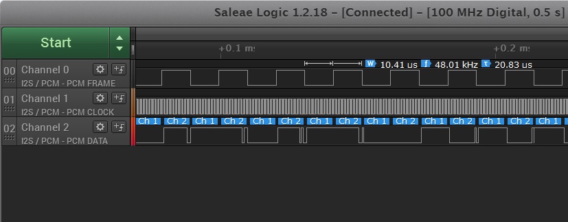
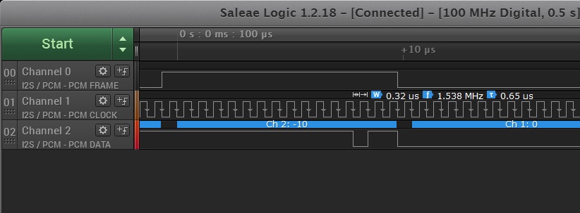
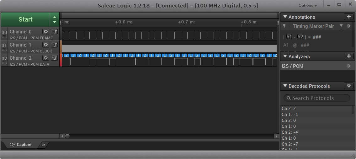
There are no connections to the other mcasp0 signals. Here are analyzer captures during arecord showing the BCK, LRCK and DATA signals on the i2s bus connected to mcasp0.

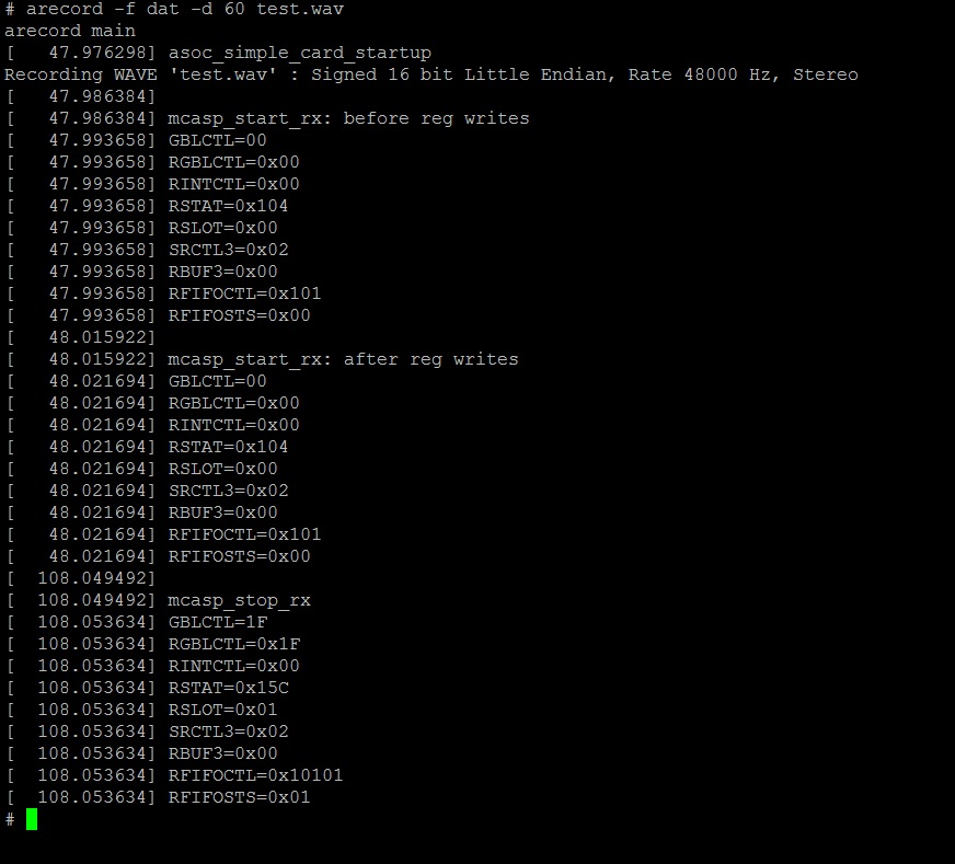
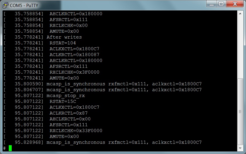
I added register reads, writes and printk statements to davinci-mcasp.c to help troubleshoot this problem. The labels should match the names in "AM437x and AMIC120 ARM® Cortex™-A9 ProcessorsTechnical Reference Manual" with the omission of MCASP_. The first captures shows the contents of the registers that I think have an impact prior to writing to them in start_rx.

The next capture shows the contents of the registers after the writes and then when stop_rx is called. Here is the code for the register writes which includes setting bit 6 in ACLKXCTL so that there is no dependency between the TX clocks and RX clocks. Here is code where I write new values to registers:

mcasp_set_reg(mcasp, DAVINCI_MCASP_RXCLKCHK_REG, 0x003F0000);
mcasp_set_reg(mcasp, DAVINCI_MCASP_RXSTAT_REG, 0xFFFFFFFF);
mcasp_set_bits(mcasp, DAVINCI_MCASP_ACLKXCTL_REG, TX_ASYNC);
__davinci_mcasp_set_clkdiv(mcasp, MCASP_CLKDIV_BCLK, 8, 0);

Setting bit 6 of ACLKXCTL got me passed the problem of the interrupt not firing but the captured file is all zeros (except for the header) even though the analyzer trace shows data. I am still getting an RX clock failure indication and I think it might be related to my problem.

I would like to get some direction where to look next. Any help would be appreciated.

  • Hi Nick,

    Do you use AM437x TI PSDK? If yes, which version?

    I see you have "msp0_pcm1862_pins_default:", may be you have typo in your DTS file, this looks like should be mcasp0_pcm1862_pins_default. Can you attach your DTS file for review?

    Meanwhile you can refer to the below documents for debug hints:

    processors.wiki.ti.com/.../Linux_Core_Audio_User's_Guide
    processors.wiki.ti.com/.../Sitara_Linux_Audio_DAC_Example

    www.ti.com/.../sprac10.pdf
    www.ti.com/.../sprac09a.pdf

    Regards,
    Pavel
  • We started with ti-processor-sdk-linux-am437x-evm-04.03.00.05 but are using buildroot-2018.05 because the sdk did not have the pcm186x driver. As was indicated in a previous post TI is no longer supporting the pcm186x driver for linux.

    The register reads and writes in my terminal captures are directly from the MCASP interface from the davinici-mcasp driver. The initial values may be impacted by the OS via the davinci-mcasp but the driver is in control of the mcasp register access.

    The msp in the post is just a typo. Here's the the complete .dts file I'm using:

    /*
     * Copyright (C) 2014 Texas Instruments Incorporated - http://www.ti.com/
     *
     * This program is free software; you can redistribute it and/or modify
     * it under the terms of the GNU General Public License version 2 as
     * published by the Free Software Foundation.
     */

    /* AM437x SK EVM */

    /dts-v1/;

    #include "am4372.dtsi"
    #include <dt-bindings/pinctrl/am43xx.h>
    #include <dt-bindings/pwm/pwm.h>
    #include <dt-bindings/gpio/gpio.h>
    #include <dt-bindings/input/input.h>

    / {
        model = "TI AM437x SK EVM";
        compatible = "ti,am437x-sk-evm","ti,am4372","ti,am43";

        aliases {
            display0 = &lcd0;
        };

        chosen {
            stdout-path = &uart0;
        };

        /* fixed 32k external oscillator clock */
        clk_32k_rtc: clk_32k_rtc {
            #clock-cells = <0>;
            compatible = "fixed-clock";
            clock-frequency = <32768>;
        };

        lcd_bl: backlight {
            compatible = "pwm-backlight";
            pwms = <&ecap0 0 50000 PWM_POLARITY_INVERTED>;
            brightness-levels = <0 51 53 56 62 75 101 152 255>;
            default-brightness-level = <8>;
        };

        /*TARG*/
        sound {
            compatible = "simple-audio-card";
            simple-audio-card,name = "PCM1862 Sound";
            simple-audio-card,widgets =
                "Line", "ADC";

                /*"Line", "Line In Jack 1",
                "Line", "Line In Jack 2",
                "Line", "Line In Jack 3",
                "Line", "Line In Jack 4";*/
            simple-audio-card,routing =

                "VINL1", "ADC Left Capture Source",
                "VINR1", "ADC Right Capture Source",
                "VINL2", "ADC Left Capture Source",
                "VINR2", "ADC Right Capture Source",
                "VINL3", "ADC Left Capture Source",
                "VINR3", "ADC Right Capture Source",
                "VINL4", "ADC Left Capture Source",
                "VINR4", "ADC Right Capture Source",

                "ADC Left Capture Source", "ADC",
                "ADC Right Capture Source", "ADC";

                /*"Line In Jack 1", "VINL1",
                "Line In Jack 1", "VINR1",
                "Line In Jack 2", "VINL2",
                "Line In Jack 2", "VINR2",
                "Line In Jack 3", "VINL3",
                "Line In Jack 3", "VINR3",
                "Line In Jack 4", "VINL4",
                "Line In Jack 4", "VINR4";*/

            simple-audio-card,format = "i2s";

            simple-audio-card,bitclock-master = <&sound0_master>;
            simple-audio-card,frame-master = <&sound0_master>;

            simple-audio-card,cpu {
                sound-dai = <&mcasp0>;
                system-clock-frequency = <24000000>;
                system-clock-direction = "out";
            };

            sound0_master: simple-audio-card,codec {
                sound-dai = <&pcm1862>;
                system-clock-frequency = <12288000>;
            };
        };

        matrix_keypad: matrix_keypad0 {
            compatible = "gpio-matrix-keypad";

            pinctrl-names = "default";
            pinctrl-0 = <&matrix_keypad_pins>;

            debounce-delay-ms = <5>;
            col-scan-delay-us = <5>;

            row-gpios = <&gpio5 5 GPIO_ACTIVE_HIGH        /* Bank5, pin5 */
                    &gpio5 6 GPIO_ACTIVE_HIGH>;    /* Bank5, pin6 */

            col-gpios = <&gpio5 13 GPIO_ACTIVE_HIGH        /* Bank5, pin13 */
                    &gpio5 4 GPIO_ACTIVE_HIGH>;    /* Bank5, pin4 */

            linux,keymap = <
                    MATRIX_KEY(0, 0, KEY_DOWN)
                    MATRIX_KEY(0, 1, KEY_RIGHT)
                    MATRIX_KEY(1, 0, KEY_LEFT)
                    MATRIX_KEY(1, 1, KEY_UP)
                >;
        };

        leds {
            compatible = "gpio-leds";

            pinctrl-names = "default";
            pinctrl-0 = <&leds_pins>;

            led0 {
                label = "am437x-sk:red:heartbeat";
                gpios = <&gpio5 0 GPIO_ACTIVE_HIGH>;    /* Bank 5, pin 0 */
                linux,default-trigger = "heartbeat";
                default-state = "off";
            };

            led1 {
                label = "am437x-sk:green:mmc1";
                gpios = <&gpio5 1 GPIO_ACTIVE_HIGH>;    /* Bank 5, pin 1 */
                linux,default-trigger = "mmc0";
                default-state = "off";
            };

            led2 {
                label = "am437x-sk:blue:cpu0";
                gpios = <&gpio5 2 GPIO_ACTIVE_HIGH>;    /* Bank 5, pin 2 */
                linux,default-trigger = "cpu0";
                default-state = "off";
            };

            led3 {
                label = "am437x-sk:blue:usr3";
                gpios = <&gpio5 3 GPIO_ACTIVE_HIGH>;    /* Bank 5, pin 3 */
                default-state = "off";
            };
        };

        lcd0: display {
            compatible = "newhaven,nhd-4.3-480272ef-atxl", "panel-dpi";
            label = "lcd";

            pinctrl-names = "default";
            pinctrl-0 = <&lcd_pins>;

            backlight = <&lcd_bl>;

            enable-gpios = <&gpio1 7 GPIO_ACTIVE_HIGH>;

            panel-timing {
                clock-frequency = <9000000>;
                hactive = <480>;
                vactive = <272>;
                hfront-porch = <2>;
                hback-porch = <2>;
                hsync-len = <41>;
                vfront-porch = <2>;
                vback-porch = <2>;
                vsync-len = <10>;
                hsync-active = <0>;
                vsync-active = <0>;
                de-active = <1>;
                pixelclk-active = <1>;
            };

            port {
                lcd_in: endpoint {
                    remote-endpoint = <&dpi_out>;
                };
            };
        };
    };

    &am43xx_pinmux {

    /* TARG */
    spi2_cc1310_pins_default: spi2_cc1310_pins_default {
        pinctrl-single,pins = <
            0x260 ( PIN_INPUT | MUX_MODE0 ) /* (N20) spi2_sclk.spi2_sclk */
            0x264 ( PIN_INPUT | MUX_MODE0 ) /* (P22) spi2_d0.spi2_d0 */
            0x268 ( PIN_OUTPUT | MUX_MODE0 ) /* (P20) spi2_d1.spi2_d1 */
            0x26c ( PIN_OUTPUT | MUX_MODE0 ) /* (T23) spi2_cs0.spi2_cs0 */
        >;
    };


    /* TARG */
    mcasp0_pcm1862_pins_default: mcasp0_pcm1862_pins_default {
        pinctrl-single,pins = <
            0x19c ( PIN_INPUT | MUX_MODE0 ) /* (M24) mcasp0_ahclkr.mcasp0_ahclkr */
            0x1a0 ( PIN_INPUT | MUX_MODE0 ) /* (L23) mcasp0_aclkr.mcasp0_aclkr */
            0x1a4 ( PIN_INPUT | MUX_MODE0 ) /* (K23) mcasp0_fsr.mcasp0_fsr */
            0x1ac ( PIN_INPUT | MUX_MODE2 ) /* (L24) mcasp0_ahclkx.mcasp0_axr3 */
        >;
    };

    /*mcasp0_pcm1862_pins_sleep: mcasp0_pcm1862_pins_sleep {
        pinctrl-single,pins = <
            0x19c ( )
            0x1a0 ( )
            0x1a4 ( )
            0x1ac ( )
        >;
    };*/

    gpio_3_pins_default: gpio_3_pins_default {
        pinctrl-single,pins = <
            0x190 ( PIN_INPUT | MUX_MODE7 ) /* (N24) mcasp0_aclkx.gpio3[14] */
            0x194 ( PIN_INPUT | MUX_MODE7 ) /* (N22) mcasp0_fsx.gpio3[15] */
            0x198 ( PIN_INPUT | MUX_MODE7 ) /* (H23) mcasp0_axr0.gpio3[16] */
        >;
    };

    i2c1_pcm1862_pins_default: i2c1_pcm1862_pins_default {
        pinctrl-single,pins = <
            0x15c ( PIN_INPUT | MUX_MODE2 ) /* (T20) spi0_cs0.I2C1_SCL */
            0x158 ( PIN_INPUT | MUX_MODE2 ) /* (T21) spi0_d1.I2C1_SDA */
        >;
    };

    gpio0_2_pcm1862_pins_default: gpio0_2_pcm1862_pins_default {
        pinctrl-single,pins = <
            AM4372_IOPAD(0x150, PIN_INPUT | MUX_MODE7) /* spi0_sclk.gpio0_2 */
        >;
    };

        matrix_keypad_pins: matrix_keypad_pins {
            pinctrl-single,pins = <
                AM4372_IOPAD(0xa4c, PIN_OUTPUT | MUX_MODE7)    /* gpio5_13.gpio5_13 */
                AM4372_IOPAD(0xa50, PIN_OUTPUT | MUX_MODE7)    /* spi4_sclk.gpio5_4 */
                AM4372_IOPAD(0xa54, PIN_INPUT | MUX_MODE7)    /* spi4_d0.gpio5_5 */
                AM4372_IOPAD(0xa58, PIN_INPUT | MUX_MODE7)    /* spi4_d1.gpio5_5 */
            >;
        };


        leds_pins: leds_pins {
            pinctrl-single,pins = <
                AM4372_IOPAD(0xa28, PIN_OUTPUT | MUX_MODE7)    /* uart3_rxd.gpio5_2 */
                AM4372_IOPAD(0xa2c, PIN_OUTPUT | MUX_MODE7)    /* uart3_txd.gpio5_3 */
                AM4372_IOPAD(0xa30, PIN_OUTPUT | MUX_MODE7)    /* uart3_ctsn.gpio5_0 */
                AM4372_IOPAD(0xa34, PIN_OUTPUT | MUX_MODE7)    /* uart3_rtsn.gpio5_1 */
            >;
        };

        i2c0_pins: i2c0_pins {
            pinctrl-single,pins = <
                AM4372_IOPAD(0x988, PIN_INPUT | SLEWCTRL_FAST | MUX_MODE0)  /* i2c0_sda.i2c0_sda */
                AM4372_IOPAD(0x98c, PIN_INPUT | SLEWCTRL_FAST | MUX_MODE0)  /* i2c0_scl.i2c0_scl */
            >;
        };

    //    i2c1_pins: i2c1_pins {
    //        pinctrl-single,pins = <
    //            AM4372_IOPAD(0x95c, PIN_INPUT | SLEWCTRL_FAST | MUX_MODE2)  /* spi0_cs0.i2c1_scl */
    //            AM4372_IOPAD(0x958, PIN_INPUT | SLEWCTRL_FAST | MUX_MODE2)  /* spi0_d1.i2c1_sda  */
    //        >;
    //    };

        mmc1_pins: pinmux_mmc1_pins {
            pinctrl-single,pins = <
                AM4372_IOPAD(0x8f0, PIN_INPUT | MUX_MODE0) /* mmc0_dat3.mmc0_dat3 */
                AM4372_IOPAD(0x8f4, PIN_INPUT | MUX_MODE0) /* mmc0_dat2.mmc0_dat2 */
                AM4372_IOPAD(0x8f8, PIN_INPUT | MUX_MODE0) /* mmc0_dat1.mmc0_dat1 */
                AM4372_IOPAD(0x8fc, PIN_INPUT | MUX_MODE0) /* mmc0_dat0.mmc0_dat0 */
                AM4372_IOPAD(0x900, PIN_INPUT | MUX_MODE0) /* mmc0_clk.mmc0_clk */
                AM4372_IOPAD(0x904, PIN_INPUT | MUX_MODE0) /* mmc0_cmd.mmc0_cmd */
                AM4372_IOPAD(0x960, PIN_INPUT | MUX_MODE7) /* spi0_cs1.gpio0_6 */
            >;
        };

        ecap0_pins: backlight_pins {
            pinctrl-single,pins = <
                AM4372_IOPAD(0x964, PIN_OUTPUT | MUX_MODE0) /* eCAP0_in_PWM0_out.eCAP0_in_PWM0_out */
            >;
        };

        edt_ft5306_ts_pins: edt_ft5306_ts_pins {
            pinctrl-single,pins = <
                AM4372_IOPAD(0x874, PIN_INPUT | MUX_MODE7)    /* gpmc_wpn.gpio0_31 */
                AM4372_IOPAD(0x878, PIN_OUTPUT | MUX_MODE7)    /* gpmc_be1n.gpio1_28 */
            >;
        };

        vpfe0_pins_default: vpfe0_pins_default {
            pinctrl-single,pins = <
                AM4372_IOPAD(0x9b0, PIN_INPUT_PULLUP | MUX_MODE0)  /* cam0_hd mode 0*/
                AM4372_IOPAD(0x9b4, PIN_INPUT_PULLUP | MUX_MODE0)  /* cam0_vd mode 0*/
                AM4372_IOPAD(0x9b8, PIN_INPUT_PULLUP | MUX_MODE0)  /* cam0_field mode 0*/
                AM4372_IOPAD(0x9bc, PIN_INPUT_PULLUP | MUX_MODE0)  /* cam0_wen mode 0*/
                AM4372_IOPAD(0x9c0, PIN_INPUT_PULLUP | MUX_MODE0)  /* cam0_pclk mode 0*/
                AM4372_IOPAD(0x9c4, PIN_INPUT_PULLUP | MUX_MODE0)  /* cam0_data8 mode 0*/
                AM4372_IOPAD(0x9c8, PIN_INPUT_PULLUP | MUX_MODE0)  /* cam0_data9 mode 0*/
                AM4372_IOPAD(0xa08, PIN_INPUT_PULLUP | MUX_MODE0)  /* cam0_data0 mode 0*/
                AM4372_IOPAD(0xa0c, PIN_INPUT_PULLUP | MUX_MODE0)  /* cam0_data1 mode 0*/
                AM4372_IOPAD(0xa10, PIN_INPUT_PULLUP | MUX_MODE0)  /* cam0_data2 mode 0*/
                AM4372_IOPAD(0xa14, PIN_INPUT_PULLUP | MUX_MODE0)  /* cam0_data3 mode 0*/
                AM4372_IOPAD(0xa18, PIN_INPUT_PULLUP | MUX_MODE0)  /* cam0_data4 mode 0*/
                AM4372_IOPAD(0xa1c, PIN_INPUT_PULLUP | MUX_MODE0)  /* cam0_data5 mode 0*/
                AM4372_IOPAD(0xa20, PIN_INPUT_PULLUP | MUX_MODE0)  /* cam0_data6 mode 0*/
                AM4372_IOPAD(0xa24, PIN_INPUT_PULLUP | MUX_MODE0)  /* cam0_data7 mode 0*/
            >;
        };

        vpfe0_pins_sleep: vpfe0_pins_sleep {
            pinctrl-single,pins = <
                AM4372_IOPAD(0x9b0, DS0_PULL_UP_DOWN_EN | INPUT_EN | MUX_MODE7)
                AM4372_IOPAD(0x9b4, DS0_PULL_UP_DOWN_EN | INPUT_EN | MUX_MODE7)
                AM4372_IOPAD(0x9b8, DS0_PULL_UP_DOWN_EN | INPUT_EN | MUX_MODE7)
                AM4372_IOPAD(0x9bc, DS0_PULL_UP_DOWN_EN | INPUT_EN | MUX_MODE7)
                AM4372_IOPAD(0x9c0, DS0_PULL_UP_DOWN_EN | INPUT_EN | MUX_MODE7)
                AM4372_IOPAD(0x9c4, DS0_PULL_UP_DOWN_EN | INPUT_EN | MUX_MODE7)
                AM4372_IOPAD(0x9c8, DS0_PULL_UP_DOWN_EN | INPUT_EN | MUX_MODE7)
                AM4372_IOPAD(0xa08, DS0_PULL_UP_DOWN_EN | INPUT_EN | MUX_MODE7)
                AM4372_IOPAD(0xa0c, DS0_PULL_UP_DOWN_EN | INPUT_EN | MUX_MODE7)
                AM4372_IOPAD(0xa10, DS0_PULL_UP_DOWN_EN | INPUT_EN | MUX_MODE7)
                AM4372_IOPAD(0xa14, DS0_PULL_UP_DOWN_EN | INPUT_EN | MUX_MODE7)
                AM4372_IOPAD(0xa18, DS0_PULL_UP_DOWN_EN | INPUT_EN | MUX_MODE7)
                AM4372_IOPAD(0xa1c, DS0_PULL_UP_DOWN_EN | INPUT_EN | MUX_MODE7)
                AM4372_IOPAD(0xa20, DS0_PULL_UP_DOWN_EN | INPUT_EN | MUX_MODE7)
                AM4372_IOPAD(0xa24, DS0_PULL_UP_DOWN_EN | INPUT_EN | MUX_MODE7)
            >;
        };

        clkout1_pin: pinmux_clkout1_pin {
            pinctrl-single,pins = <
                0x270 (PIN_OUTPUT_PULLDOWN | MUX_MODE3)    /* XDMA_EVENT_INTR0/CLKOUT1 */
            >;
        };

        cpsw_default: cpsw_default {
            pinctrl-single,pins = <
                /* Slave 1 */
                AM4372_IOPAD(0x92c, PIN_OUTPUT | MUX_MODE2)    /* mii1_txclk.rmii1_tclk */
                AM4372_IOPAD(0x914, PIN_OUTPUT | MUX_MODE2)    /* mii1_txen.rgmii1_tctl */
                AM4372_IOPAD(0x928, PIN_OUTPUT | MUX_MODE2)    /* mii1_txd0.rgmii1_td0 */
                AM4372_IOPAD(0x924, PIN_OUTPUT | MUX_MODE2)    /* mii1_txd1.rgmii1_td1 */
                AM4372_IOPAD(0x920, PIN_OUTPUT | MUX_MODE2)    /* mii1_txd0.rgmii1_td2 */
                AM4372_IOPAD(0x91c, PIN_OUTPUT | MUX_MODE2)    /* mii1_txd1.rgmii1_td3 */
                AM4372_IOPAD(0x930, PIN_INPUT | MUX_MODE2)    /* mii1_rxclk.rmii1_rclk */
                AM4372_IOPAD(0x918, PIN_INPUT | MUX_MODE2)    /* mii1_rxdv.rgmii1_rctl */
                AM4372_IOPAD(0x940, PIN_INPUT | MUX_MODE2)    /* mii1_rxd0.rgmii1_rd0 */
                AM4372_IOPAD(0x93c, PIN_INPUT | MUX_MODE2)    /* mii1_rxd1.rgmii1_rd1 */
                AM4372_IOPAD(0x938, PIN_INPUT | MUX_MODE2)    /* mii1_rxd0.rgmii1_rd2 */
                AM4372_IOPAD(0x934, PIN_INPUT | MUX_MODE2)    /* mii1_rxd1.rgmii1_rd3 */

                /* Slave 2 */
                AM4372_IOPAD(0x858, PIN_OUTPUT | MUX_MODE2)    /* gpmc_a6.rgmii2_tclk */
                AM4372_IOPAD(0x840, PIN_OUTPUT | MUX_MODE2)    /* gpmc_a0.rgmii2_tctl */
                AM4372_IOPAD(0x854, PIN_OUTPUT | MUX_MODE2)    /* gpmc_a5.rgmii2_td0 */
                AM4372_IOPAD(0x850, PIN_OUTPUT | MUX_MODE2)    /* gpmc_a4.rgmii2_td1 */
                AM4372_IOPAD(0x84c, PIN_OUTPUT | MUX_MODE2)    /* gpmc_a3.rgmii2_td2 */
                AM4372_IOPAD(0x848, PIN_OUTPUT | MUX_MODE2)    /* gpmc_a2.rgmii2_td3 */
                AM4372_IOPAD(0x85c, PIN_INPUT | MUX_MODE2)    /* gpmc_a7.rgmii2_rclk */
                AM4372_IOPAD(0x844, PIN_INPUT | MUX_MODE2)    /* gpmc_a1.rgmii2_rtcl */
                AM4372_IOPAD(0x86c, PIN_INPUT | MUX_MODE2)    /* gpmc_a11.rgmii2_rd0 */
                AM4372_IOPAD(0x868, PIN_INPUT | MUX_MODE2)    /* gpmc_a10.rgmii2_rd1 */
                AM4372_IOPAD(0x864, PIN_INPUT | MUX_MODE2)    /* gpmc_a9.rgmii2_rd2 */
                AM4372_IOPAD(0x860, PIN_INPUT | MUX_MODE2)    /* gpmc_a8.rgmii2_rd3 */
            >;
        };

        cpsw_sleep: cpsw_sleep {
            pinctrl-single,pins = <
                /* Slave 1 reset value */
                AM4372_IOPAD(0x92c, PIN_INPUT_PULLDOWN | MUX_MODE7)
                AM4372_IOPAD(0x914, PIN_INPUT_PULLDOWN | MUX_MODE7)
                AM4372_IOPAD(0x928, PIN_INPUT_PULLDOWN | MUX_MODE7)
                AM4372_IOPAD(0x924, PIN_INPUT_PULLDOWN | MUX_MODE7)
                AM4372_IOPAD(0x920, PIN_INPUT_PULLDOWN | MUX_MODE7)
                AM4372_IOPAD(0x91c, PIN_INPUT_PULLDOWN | MUX_MODE7)
                AM4372_IOPAD(0x930, PIN_INPUT_PULLDOWN | MUX_MODE7)
                AM4372_IOPAD(0x918, PIN_INPUT_PULLDOWN | MUX_MODE7)
                AM4372_IOPAD(0x940, PIN_INPUT_PULLDOWN | MUX_MODE7)
                AM4372_IOPAD(0x93c, PIN_INPUT_PULLDOWN | MUX_MODE7)
                AM4372_IOPAD(0x938, PIN_INPUT_PULLDOWN | MUX_MODE7)
                AM4372_IOPAD(0x934, PIN_INPUT_PULLDOWN | MUX_MODE7)

                /* Slave 2 reset value */
                AM4372_IOPAD(0x858, PIN_INPUT_PULLDOWN | MUX_MODE7)
                AM4372_IOPAD(0x840, PIN_INPUT_PULLDOWN | MUX_MODE7)
                AM4372_IOPAD(0x854, PIN_INPUT_PULLDOWN | MUX_MODE7)
                AM4372_IOPAD(0x850, PIN_INPUT_PULLDOWN | MUX_MODE7)
                AM4372_IOPAD(0x84c, PIN_INPUT_PULLDOWN | MUX_MODE7)
                AM4372_IOPAD(0x848, PIN_INPUT_PULLDOWN | MUX_MODE7)
                AM4372_IOPAD(0x85c, PIN_INPUT_PULLDOWN | MUX_MODE7)
                AM4372_IOPAD(0x844, PIN_INPUT_PULLDOWN | MUX_MODE7)
                AM4372_IOPAD(0x86c, PIN_INPUT_PULLDOWN | MUX_MODE7)
                AM4372_IOPAD(0x868, PIN_INPUT_PULLDOWN | MUX_MODE7)
                AM4372_IOPAD(0x864, PIN_INPUT_PULLDOWN | MUX_MODE7)
                AM4372_IOPAD(0x860, PIN_INPUT_PULLDOWN | MUX_MODE7)
            >;
        };

        davinci_mdio_default: davinci_mdio_default {
            pinctrl-single,pins = <
                /* MDIO */
                AM4372_IOPAD(0x948, PIN_INPUT | SLEWCTRL_FAST | MUX_MODE0)    /* mdio_data.mdio_data */
                AM4372_IOPAD(0x94c, PIN_OUTPUT | MUX_MODE0)            /* mdio_clk.mdio_clk */
            >;
        };

        davinci_mdio_sleep: davinci_mdio_sleep {
            pinctrl-single,pins = <
                /* MDIO reset value */
                AM4372_IOPAD(0x948, PIN_INPUT_PULLDOWN | MUX_MODE7)
                AM4372_IOPAD(0x94c, PIN_INPUT_PULLDOWN | MUX_MODE7)
            >;
        };

        dss_pins: dss_pins {
            pinctrl-single,pins = <
                AM4372_IOPAD(0x820, PIN_OUTPUT | MUX_MODE1)    /* gpmc ad 8 -> DSS DATA 23 */
                AM4372_IOPAD(0x824, PIN_OUTPUT | MUX_MODE1)
                AM4372_IOPAD(0x828, PIN_OUTPUT | MUX_MODE1)
                AM4372_IOPAD(0x82c, PIN_OUTPUT | MUX_MODE1)
                AM4372_IOPAD(0x830, PIN_OUTPUT | MUX_MODE1)
                AM4372_IOPAD(0x834, PIN_OUTPUT | MUX_MODE1)
                AM4372_IOPAD(0x838, PIN_OUTPUT | MUX_MODE1)
                AM4372_IOPAD(0x83c, PIN_OUTPUT | MUX_MODE1)    /* gpmc ad 15 -> DSS DATA 16 */
                AM4372_IOPAD(0x8a0, PIN_OUTPUT | MUX_MODE0)    /* DSS DATA 0 */
                AM4372_IOPAD(0x8a4, PIN_OUTPUT | MUX_MODE0)
                AM4372_IOPAD(0x8a8, PIN_OUTPUT | MUX_MODE0)
                AM4372_IOPAD(0x8ac, PIN_OUTPUT | MUX_MODE0)
                AM4372_IOPAD(0x8b0, PIN_OUTPUT | MUX_MODE0)
                AM4372_IOPAD(0x8b4, PIN_OUTPUT | MUX_MODE0)
                AM4372_IOPAD(0x8b8, PIN_OUTPUT | MUX_MODE0)
                AM4372_IOPAD(0x8bc, PIN_OUTPUT | MUX_MODE0)
                AM4372_IOPAD(0x8c0, PIN_OUTPUT | MUX_MODE0)
                AM4372_IOPAD(0x8c4, PIN_OUTPUT | MUX_MODE0)
                AM4372_IOPAD(0x8c8, PIN_OUTPUT | MUX_MODE0)
                AM4372_IOPAD(0x8cc, PIN_OUTPUT | MUX_MODE0)
                AM4372_IOPAD(0x8d0, PIN_OUTPUT | MUX_MODE0)
                AM4372_IOPAD(0x8d4, PIN_OUTPUT | MUX_MODE0)
                AM4372_IOPAD(0x8d8, PIN_OUTPUT | MUX_MODE0)
                AM4372_IOPAD(0x8dc, PIN_OUTPUT | MUX_MODE0)    /* DSS DATA 15 */
                AM4372_IOPAD(0x8e0, PIN_OUTPUT | MUX_MODE0)    /* DSS VSYNC */
                AM4372_IOPAD(0x8e4, PIN_OUTPUT | MUX_MODE0)    /* DSS HSYNC */
                AM4372_IOPAD(0x8e8, PIN_OUTPUT | MUX_MODE0)    /* DSS PCLK */
                AM4372_IOPAD(0x8ec, PIN_OUTPUT | MUX_MODE0)    /* DSS AC BIAS EN */

            >;
        };

        qspi_pins: qspi_pins {
            pinctrl-single,pins = <
                AM4372_IOPAD(0x87c, PIN_OUTPUT | MUX_MODE3)    /* gpmc_csn0.qspi_csn */
                AM4372_IOPAD(0x888, PIN_OUTPUT | MUX_MODE2)    /* gpmc_csn3.qspi_clk */
                AM4372_IOPAD(0x890, PIN_INPUT | MUX_MODE3)    /* gpmc_advn_ale.qspi_d0 */
                AM4372_IOPAD(0x894, PIN_INPUT | MUX_MODE3)    /* gpmc_oen_ren.qspi_d1 */
                AM4372_IOPAD(0x898, PIN_INPUT | MUX_MODE3)    /* gpmc_wen.qspi_d2 */
                AM4372_IOPAD(0x89c, PIN_INPUT | MUX_MODE3)    /* gpmc_be0n_cle.qspi_d3 */
            >;
        };

        mcasp1_pins: mcasp1_pins {
            pinctrl-single,pins = <
                AM4372_IOPAD(0x90c, PIN_INPUT_PULLDOWN | MUX_MODE4)    /* mii1_crs.mcasp1_aclkx */
                AM4372_IOPAD(0x910, PIN_INPUT_PULLDOWN | MUX_MODE4)    /* mii1_rxerr.mcasp1_fsx */
                AM4372_IOPAD(0x908, PIN_OUTPUT_PULLDOWN | MUX_MODE4)    /* mii1_col.mcasp1_axr2 */
                AM4372_IOPAD(0x944, PIN_INPUT_PULLDOWN | MUX_MODE4)    /* rmii1_ref_clk.mcasp1_axr3 */
            >;
        };

        mcasp1_pins_sleep: mcasp1_pins_sleep {
            pinctrl-single,pins = <
                AM4372_IOPAD(0x90c, PIN_INPUT_PULLDOWN | MUX_MODE7)
                AM4372_IOPAD(0x910, PIN_INPUT_PULLDOWN | MUX_MODE7)
                AM4372_IOPAD(0x908, PIN_INPUT_PULLDOWN | MUX_MODE7)
                AM4372_IOPAD(0x944, PIN_INPUT_PULLDOWN | MUX_MODE7)
            >;
        };

        lcd_pins: lcd_pins {
            pinctrl-single,pins = <
                AM4372_IOPAD(0x81c, PIN_OUTPUT_PULLDOWN | MUX_MODE7) /* gpcm_ad7.gpio1_7 */
            >;
        };

        usb1_pins: usb1_pins {
            pinctrl-single,pins = <
                AM4372_IOPAD(0xac0, PIN_OUTPUT | MUX_MODE0) /* usb0_drvvbus.usb0_drvvbus */
            >;
        };

        usb2_pins: usb2_pins {
            pinctrl-single,pins = <
                AM4372_IOPAD(0xac4, PIN_OUTPUT | MUX_MODE0) /* usb0_drvvbus.usb0_drvvbus */
            >;
        };
    };

    /* TARG */
    &spi2 {
        pinctrl-names = "default";
        pinctrl-0 = <&spi2_cc1310_pins_default>;
        status = "okay";

        spidev@0 {
            compatible = "rohm,dh2228fv";
            spi-max-frequency = <5000000>;
            reg = <0x0>;
            spi-cpha;
        };
    };


    &i2c0 {
        status = "okay";
        pinctrl-names = "default";
        pinctrl-0 = <&i2c0_pins>;
        clock-frequency = <100000>;

        tps@24 {
            compatible = "ti,tps65218";
            reg = <0x24>;
            interrupts = <GIC_SPI 7 IRQ_TYPE_LEVEL_HIGH>;
            interrupt-controller;
            #interrupt-cells = <2>;

            dcdc1: regulator-dcdc1 {
                /* VDD_CORE limits min of OPP50 and max of OPP100 */
                regulator-name = "vdd_core";
                regulator-min-microvolt = <912000>;
                regulator-max-microvolt = <1144000>;
                regulator-boot-on;
                regulator-always-on;
            };

            dcdc2: regulator-dcdc2 {
                /* VDD_MPU limits min of OPP50 and max of OPP_NITRO */
                regulator-name = "vdd_mpu";
                regulator-min-microvolt = <912000>;
                regulator-max-microvolt = <1378000>;
                regulator-boot-on;
                regulator-always-on;
            };

            dcdc3: regulator-dcdc3 {
                regulator-name = "vdds_ddr";
                regulator-boot-on;
                regulator-always-on;
                regulator-state-mem {
                    regulator-on-in-suspend;
                };
                regulator-state-disk {
                    regulator-off-in-suspend;
                };
            };

            dcdc4: regulator-dcdc4 {
                regulator-name = "v3_3d";
                regulator-min-microvolt = <3300000>;
                regulator-max-microvolt = <3300000>;
                regulator-boot-on;
                regulator-always-on;
            };

            dcdc5: regulator-dcdc5 {
                compatible = "ti,tps65218-dcdc5";
                regulator-name = "v1_0bat";
                regulator-min-microvolt = <1000000>;
                regulator-max-microvolt = <1000000>;
                regulator-boot-on;
                regulator-always-on;
                regulator-state-mem {
                    regulator-on-in-suspend;
                };
            };

            dcdc6: regulator-dcdc6 {
                compatible = "ti,tps65218-dcdc6";
                regulator-name = "v1_8bat";
                regulator-min-microvolt = <1800000>;
                regulator-max-microvolt = <1800000>;
                regulator-boot-on;
                regulator-always-on;
                regulator-state-mem {
                    regulator-on-in-suspend;
                };
            };

            ldo1: regulator-ldo1 {
                regulator-name = "v1_8d";
                regulator-min-microvolt = <1800000>;
                regulator-max-microvolt = <1800000>;
                regulator-boot-on;
                regulator-always-on;
            };

            power-button {
                compatible = "ti,tps65218-pwrbutton";
                status = "okay";
                interrupts = <3 IRQ_TYPE_EDGE_BOTH>;
            };
        };

        at24@50 {
            compatible = "at24,24c256";
            pagesize = <64>;
            reg = <0x50>;
        };
    };

    /*TARG*/
    &i2c1 {
        pinctrl-names = "default";
        pinctrl-0 = <&i2c1_pcm1862_pins_default>;

        status = "okay";
        clock-frequency = <100000>;

        pcm1862: pcm1862@4b {
            compatible = "ti,pcm1862";
            #sound-dai-cells = <0>;
            reg = <0x4b>;
            status = "okay";

            /*AVDD-supply = <&dcdc4>;
            IOVDD-supply = <&dcdc4>;
            DVDD-supply = <&dcdc4>;*/
            avdd = <&dcdc4>;
            iovdd = <&dcdc4>;
            dvdd = <&dcdc4>;
        };
    };

    /*&i2c1 {
        status = "okay";
        pinctrl-names = "default";
        pinctrl-0 = <&i2c1_pins>;
        clock-frequency = <400000>;

        ov2659@30 {
            compatible = "ovti,ov2659";
            reg = <0x30>;
            pinctrl-names = "default";
            pinctrl-0 = <&clkout1_pin>;

            clocks = <&clkout1_mux_ck>;
            clock-names = "xvclk";
            assigned-clocks = <&clkout1_mux_ck>;
            assigned-clock-parents = <&clkout1_osc_div_ck>;

            port {
                ov2659_1: endpoint {
                    remote-endpoint = <&vpfe0_ep>;
                    link-frequencies = /bits/ 64 <70000000>;
                };
            };
        };

        edt-ft5306@38 {
            status = "okay";
            compatible = "edt,edt-ft5306", "edt,edt-ft5x06";
            pinctrl-names = "default";
            pinctrl-0 = <&edt_ft5306_ts_pins>;

            reg = <0x38>;
            interrupt-parent = <&gpio0>;
            interrupts = <31 IRQ_TYPE_EDGE_FALLING>;

            reset-gpios = <&gpio1 28 GPIO_ACTIVE_LOW>;

            touchscreen-size-x = <480>;
            touchscreen-size-y = <272>;
        };

        tlv320aic3106: tlv320aic3106@1b {
            #sound-dai-cells = <0>;
            compatible = "ti,tlv320aic3106";
            reg = <0x1b>;
            status = "okay";

            AVDD-supply = <&dcdc4>;
            IOVDD-supply = <&dcdc4>;
            DRVDD-supply = <&dcdc4>;
            DVDD-supply = <&ldo1>;
        };

        lis331dlh@18 {
            compatible = "st,lis331dlh";
            reg = <0x18>;
            status = "okay";

            Vdd-supply = <&dcdc4>;
            Vdd_IO-supply = <&dcdc4>;
            interrupts-extended = <&gpio1 6 0>, <&gpio2 1 0>;
        };
    };*/

    &epwmss0 {
        status = "okay";
    };

    &ecap0 {
        status = "okay";
        pinctrl-names = "default";
        pinctrl-0 = <&ecap0_pins>;
    };

    &gpio0 {
        status = "okay";
    };

    &gpio1 {
        status = "okay";
    };

    &gpio5 {
        status = "okay";
    };

    &mmc1 {
        status = "okay";
        pinctrl-names = "default";
        pinctrl-0 = <&mmc1_pins>;

        vmmc-supply = <&dcdc4>;
        bus-width = <4>;
        cd-gpios = <&gpio0 6 GPIO_ACTIVE_LOW>;
    };

    &usb2_phy1 {
        status = "okay";
    };

    &usb1 {
        dr_mode = "otg";
        status = "okay";
        pinctrl-names = "default";
        pinctrl-0 = <&usb1_pins>;
    };

    &usb2_phy2 {
        status = "okay";
    };

    &usb2 {
        dr_mode = "host";
        status = "okay";
        pinctrl-names = "default";
        pinctrl-0 = <&usb2_pins>;
    };

    &qspi {
        status = "okay";
        pinctrl-names = "default";
        pinctrl-0 = <&qspi_pins>;

        spi-max-frequency = <48000000>;
        m25p80@0 {
            compatible = "mx66l51235l";
            spi-max-frequency = <48000000>;
            reg = <0>;
            spi-cpol;
            spi-cpha;
            spi-tx-bus-width = <1>;
            spi-rx-bus-width = <4>;
            #address-cells = <1>;
            #size-cells = <1>;

            /* MTD partition table.
             * The ROM checks the first 512KiB
             * for a valid file to boot(XIP).
             */
            partition@0 {
                label = "QSPI.U_BOOT";
                reg = <0x00000000 0x000080000>;
            };
            partition@1 {
                label = "QSPI.U_BOOT.backup";
                reg = <0x00080000 0x00080000>;
            };
            partition@2 {
                label = "QSPI.U-BOOT-SPL_OS";
                reg = <0x00100000 0x00010000>;
            };
            partition@3 {
                label = "QSPI.U_BOOT_ENV";
                reg = <0x00110000 0x00010000>;
            };
            partition@4 {
                label = "QSPI.U-BOOT-ENV.backup";
                reg = <0x00120000 0x00010000>;
            };
            partition@5 {
                label = "QSPI.KERNEL";
                reg = <0x00130000 0x0800000>;
            };
            partition@6 {
                label = "QSPI.FILESYSTEM";
                reg = <0x00930000 0x36D0000>;
            };
        };
    };

    &mac {
        pinctrl-names = "default", "sleep";
        pinctrl-0 = <&cpsw_default>;
        pinctrl-1 = <&cpsw_sleep>;
        dual_emac = <1>;
        status = "okay";
    };

    &davinci_mdio {
        pinctrl-names = "default", "sleep";
        pinctrl-0 = <&davinci_mdio_default>;
        pinctrl-1 = <&davinci_mdio_sleep>;
        status = "okay";
    };

    &cpsw_emac0 {
        phy_id = <&davinci_mdio>, <4>;
        phy-mode = "rgmii";
        dual_emac_res_vlan = <1>;
    };

    &cpsw_emac1 {
        phy_id = <&davinci_mdio>, <5>;
        phy-mode = "rgmii";
        dual_emac_res_vlan = <2>;
    };

    &elm {
        status = "okay";
    };

    &mcasp1 {
        #sound-dai-cells = <0>;
        pinctrl-names = "default", "sleep";
        pinctrl-0 = <&mcasp1_pins>;
        pinctrl-1 = <&mcasp1_pins_sleep>;

        status = "okay";

        op-mode = <0>;
        tdm-slots = <2>;
        serial-dir = <
            0 0 1 2
        >;

        tx-num-evt = <1>;
        rx-num-evt = <1>;
    };

    /*TARG*/
    /*&mcasp0 {
        #sound-dai-cells = <0>;
        pinctrl-names = "default";
        pinctrl-0 = <&mcasp0_pcm1862_pins_default>;

        status = "okay";

        op-mode = <0>;
        tdm-slots = <2>;
        serial-dir = <
            0 0 0 2
        >;

        tx-num-evt = <1>;
        rx-num-evt = <1>;
    };*/

    &mcasp0 {
        #sound-dai-cells = <0>;
        pinctrl-names = "default";
        pinctrl-0 = <&mcasp0_pcm1862_pins_default>;

        compatible = "ti,da830-mcasp-audio";
        /*reg = <0x100000 0x3000>;
        reg-names = "mpu";*/
        interrupts = <82 83>;

        status = "okay";

        op-mode = <0>;
        tdm-slots = <2>;
        serial-dir = <
            0 0 0 2
        >;

        tx-num-evt = <1>;
        rx-num-evt = <1>;
    };

    &dss {
        status = "okay";

        pinctrl-names = "default";
        pinctrl-0 = <&dss_pins>;

        port {
            dpi_out: endpoint@0 {
                remote-endpoint = <&lcd_in>;
                data-lines = <24>;
            };
        };
    };

    &rtc {
        clocks = <&clk_32k_rtc>, <&clk_32768_ck>;
        clock-names = "ext-clk", "int-clk";
        status = "okay";
    };

    &wdt {
        status = "okay";
    };

    &cpu {
        cpu0-supply = <&dcdc2>;
    };

    /*&vpfe0 {
        status = "okay";
        pinctrl-names = "default", "sleep";
        pinctrl-0 = <&vpfe0_pins_default>;
        pinctrl-1 = <&vpfe0_pins_sleep>;

        port {
            vpfe0_ep: endpoint {
                remote-endpoint = <&ov2659_1>;
                ti,am437x-vpfe-interface = <0>;
                bus-width = <8>;
                hsync-active = <0>;
                vsync-active = <0>;
            };
        };
    };*/

    &wkup_m3_ipc {
        ti,scale-data-fw = "am43x-evm-scale-data.bin";
    };

    &pruss_soc_bus {
        status = "okay";

        pruss1: pruss@54400000 {
            status = "okay";

            pru1_0: pru@54434000 {
                status = "okay";
            };

            pru1_1: pru@54438000 {
                status = "okay";
            };
        };

        pruss0: pruss@54440000 {
            status = "okay";

            pru0_0: pru@54474000 {
                status = "okay";
            };

            pru0_1: pru@54478000 {
                status = "okay";
            };
        };
    };

    &sgx {
        status = "okay";
    };

  • Nick Currens said:
    /* TARG */
    mcasp0_pcm1862_pins_default: mcasp0_pcm1862_pins_default {
        pinctrl-single,pins = <
            0x19c ( PIN_INPUT | MUX_MODE0 ) /* (M24) mcasp0_ahclkr.mcasp0_ahclkr */
            0x1a0 ( PIN_INPUT | MUX_MODE0 ) /* (L23) mcasp0_aclkr.mcasp0_aclkr */
            0x1a4 ( PIN_INPUT | MUX_MODE0 ) /* (K23) mcasp0_fsr.mcasp0_fsr */
            0x1ac ( PIN_INPUT | MUX_MODE2 ) /* (L24) mcasp0_ahclkx.mcasp0_axr3 */
        >;
    };

    I would suggest you to verify that McASP0 pinmux is proper in user space, with devmem2 or omapconf tool. You can check values of below registers and verify these registers have the correct and expected values:

    CTRL_CONF_MCASP0_AHCLKR  0x44E1099C

    CTRL_CONF_MCASP0_ACLKR  0x44E109A0

    CTRL_CONF_MCASP0_FSR 0x44E109A4

    CTRL_CONF_MCASP0_AHCLKX 0x44E109AC

    There might be something wrong, as in AM437x TI boards (EVM, SK, IDK) we use another approach for pinmux. Check for example McASP1 pinmux in EVM DTS file:

    linux-kernel/arch/arm/boot/dts/am437x-gp-evm.dts

    &am43xx_pinmux {

    mcasp1_pins: mcasp1_pins {
            pinctrl-single,pins = <
                AM4372_IOPAD(0x90c, PIN_INPUT_PULLDOWN | MUX_MODE4)    /* mii1_crs.mcasp1_aclkx */
                AM4372_IOPAD(0x910, PIN_INPUT_PULLDOWN | MUX_MODE4)    /* mii1_rxerr.mcasp1_fsx */
                AM4372_IOPAD(0x908, PIN_OUTPUT_PULLDOWN | MUX_MODE4)    /* mii1_col.mcasp1_axr2 */
                AM4372_IOPAD(0x944, PIN_INPUT_PULLDOWN | MUX_MODE4)    /* rmii1_ref_clk.mcasp1_axr3 */
            >;
        };

    Nick Currens said:
    &mcasp0 {
        #sound-dai-cells = <0>;
        pinctrl-names = "default";
        pinctrl-0 = <&mcasp0_pcm1862_pins_default>;

        compatible = "ti,da830-mcasp-audio";
        /*reg = <0x100000 0x3000>;
        reg-names = "mpu";*/
        interrupts = <82 83>;

        status = "okay";

        op-mode = <0>;
        tdm-slots = <2>;
        serial-dir = <
            0 0 0 2
        >;

        tx-num-evt = <1>;
        rx-num-evt = <1>;
    };

    I think some of these entries (compatible, reg-names, interrupts) should not be filled in your main DTS file. These are generic parameters and should stay at default values set in am4372.dtsi file.

    Check also below user guide, it covers similar audio ADC PCM1864 integrated with similar Sitara device AM335x.

    Regards,
    Pavel


  • In the above terminal captures

    CTRL_CONF_MCASP0_AHCLKR  is AHCLKRCTL,

    CTRL_CONF_MCASP0_ACLKR  is ACLKRCTL,

    CTRL_CONF_MCASP0_FSR is AFSRCTL and

    CTRL_CONF_MCASP0_AHCLKX is ACLKXCTL as seen by the davinci-mcasp driver. My goal is to have mcasp0 operate asynchronusly (rx clocks do not depend on tx clocks) and the LRCK and BCK clocks not derived from AHCLKR. Because I am still getting an RX clock failure in RSTAT there may be a configuration problem.

    I tried changing the mcasp0 pins to use PIN_INPUT_PULLDOWN instead of PIN_INPUT but got the same results. Also, I updated the mcasp0 definition as follows:

    &mcasp0 {
            #sound-dai-cells = <0>;
            pinctrl-names = "default";
            pinctrl-0 = <&mcasp0_pcm1862_pins_default>;

            status = "okay";

            op-mode = <0>;
            tdm-slots = <2>;
            serial-dir = <
                    0 0 0 2
            >;

            tx-num-evt = <1>;
            rx-num-evt = <1>;
    };

    All with the same results of all zeros in the capture file. I turned up the volume on my anlog audio source and verified that it is getting to the inputs of the board. Also, I ohmed out the traces between the input pins and the pins of the pcm1862.

    Let me know if you have any other ideas.

  • Nick Currens said:

    In the above terminal captures

    CTRL_CONF_MCASP0_AHCLKR  is AHCLKRCTL

    Do you mean that AHCLKRCTL from your terminal (value 0x180000) correspond to CTRL_CONF_MCASP0_AHCLKR/0x44E1099C register, NOT to MCASP0.MCASP_AHCLKRCTL/0x48038074???

    If this is what you mean, then the value in CTRL_CONF_MCASP0_AHCLKR[18]  CONF_MCASP0_AHCLKR_RXACTIVE bit is NOT correct, this value is 0 (output), while you setup this pin as input:

      0x19c ( PIN_INPUT | MUX_MODE0 ) /* (M24) mcasp0_ahclkr.mcasp0_ahclkr */


    Nick Currens said:
    CTRL_CONF_MCASP0_ACLKR  is ACLKRCTL

    Do you mean that ACLKRCTL from your terminal (value 0x180080) correspond to CTRL_CONF_MCASP0_ACLKR/0x44E109A0 register, NOT to MCASP0.MCASP_ACLKRCTL/0x48038070???

    If this is what you mean, then the value in CTRL_CONF_MCASP0_ACLKR[18]  CONF_MCASP0_ACLKR_RXACTIVE bit is NOT correct, this value is 0 (output), while you setup this pin as input:

    0x1a0 ( PIN_INPUT | MUX_MODE0 ) /* (L23) mcasp0_aclkr.mcasp0_aclkr */

    I would suggest you to check pinmux values in user space with devmem2 tool right after kernel boot up, not inside the McASP driver.

    Regards,
    Pavel

  • Sorry, I wasn't aware of how the pinmux actually works. I thought you meant the mcasp register values. Here's what I got using devmem (from busybox):

    Right or wrong, I think this is consistant with the device tree enteries. All four pins are active and in mode 0 except CTRL_CONF_MCASP0_AHCLKX (0x44E109AC) set to mode 2 (if I'm reading the spec correctly).

    Are there pin options I should try to see if they make a difference?

    Thanks for all your help so far on this.

  • Nick,

    As you are using PCM1862 codec as master, ACLKR/BCK, FSR/LRCK and AXR3/DOUT pinmux looks correct.

    I have some doubts regarding McASP AHCLKR pin usage. To which PCM1862 pin you are connecting this AHCLKR pin? Is it SCKI? I am not PCM1862 expert, but I think you need to provide clock to PCM1862 SCKI pin, when using PCM1862 as master. In the document below, PCM186x is used as master and external clock generator is used to supply 24.576MHz to SCKI pin.

    www.ti.com/.../sprac97.pdf

    To sum up, I need answers to these questions:

    - Which PCM1862 pin is connected to McASP0 AHCLKR pin?
    - What is the frequency you have on McASP0 AHCLKR pin?
    - What is the frequency you have on McASP0 ACLKR pin?
    - What is the frequency you have on McASP0 FSR pin?


    Regards,
    Pavel
  • The quick answer is:

    - Which PCM1862 pin is connected to McASP0 AHCLKR pin? Both pins are connected to an external oscillator
    - What is the frequency you have on McASP0 AHCLKR pin?  12.288mHz
    - What is the frequency you have on McASP0 ACLKR pin? 1.536mHz
    - What is the frequency you have on McASP0 FSR pin? 48kHz

    Here are the details:

    A 12.228Mhz oscillator is connected to pin 1 (CLKIN) of a PI6CV304 clock buffer with pin 3 (OE) tied to 3.3v.

    pcm1862 pin 15 (SCKI) is connected to pin 8 (Y3) of the PI6CV304 with a 22ohm resister in line.

    McASP0 AHCLKR (M24) is connected to pin 3 (Y0) of the PI6CV304 with a 22ohm resister in line.

    I have test leads on pin 18 (DOUT), pin 17 (BCK) and pin 16 (LRCK) of the pcm1862.

    From the analyzer traces above:

    BCK is ~ 1.536Mhz (consistent with stereo 16 bit samples at a sample rate of 48Khz).

    LRCK is ~ 48Khz (consistant with the specified -f dat parameter supplied with arecord)

    I also verifed that the registers in the pcm1862 have the proper values written over the i2c interface for these clock rates.

    McASP0 ACLKR (L23) is connected to pcm1862 pin 17 (BCK) with a 22ohm resister in line.

    McASP0 FSR (K23) is connected to pcm1862 pin 16 (LRCK) with a 22ohm resister in line.

    McASP0 AHCLKX (L24) is connected to pcm1862 pin 18 (DOUT) with no resister in line.

  • Nick,

    From what I understand, you do not need to use mcasp0_ahclkr pin at all. When output, this pin is used to supply other chips with clock. When input, this pin is used to produce the bit clock. But you are using McASP0 as slave, thus supply the bit clock from external chip.

    But mcasp0_ahclkr pin is not related to your main issue. Please provide me the values of the below McASP0 registers for review:

    GBLCTL
    RGBLCTL
    RINTCTL
    RSTAT
    RSLOT
    SRCTL3
    RBUF3
    RFIFOCTL
    RFIFOSTS

    You should get these register values from the mcasp linux driver, after running arecord command.

    Regards,
    Pavel
  • Pavel,

    Here's the results of the register reads:
  • Hope this helps,

    Nick

  • Nick,

    I have tried on AM437x EVM with PSDK 4.03 and I have there

    root@am437x-evm:~# arecord -f dat -d 1 test.wav
    Recording WAVE 'test.wav' : Signed 16 bit Little Endian, Rate 48000 Hz, Stereo
    [ 1718.226127] davinci-mcasp.c -> mcasp_start_rx()
    [ 1718.230721] MCASP0_CLKCTRL = 30000
    [ 1718.234148] MCASP1_CLKCTRL = 2
    [ 1718.237223] GBLCTL = 1e
    [ 1718.239684] RGBLCTL = 1f
    [ 1718.242233] RINTCTL = 0
    [ 1718.244695] RSTAT = 154
    [ 1718.247155] RSLOT = 0
    [ 1718.249441] SRCTL3 = 2
    [ 1718.251814] RBUF3 = 0
    [ 1718.254101] RFIFOCTL = 12001
    [ 1718.256998] RFIFOSTS = d
    root@am437x-evm:~# ls -al test.wav
    -rw-r--r-- 1 root root 192044 Mar 26 15:37 test.wav
    root@am437x-evm:~# arecord -f dat -d 5 test.wav
    Recording WAVE 'test.wav' : Signed 16 bit Little Endian, Rate 48000 Hz, Stereo
    [ 1904.235377] davinci-mcasp.c -> mcasp_start_rx()
    [ 1904.239971] MCASP0_CLKCTRL = 30000
    [ 1904.243396] MCASP1_CLKCTRL = 2
    [ 1904.246471] GBLCTL = 1e
    [ 1904.248932] RGBLCTL = 1f
    [ 1904.251480] RINTCTL = 0
    [ 1904.253941] RSTAT = 15c
    [ 1904.256401] RSLOT = 1
    [ 1904.258689] SRCTL3 = 2
    [ 1904.261062] RBUF3 = 0
    [ 1904.263351] RFIFOCTL = 12001
    [ 1904.266248] RFIFOSTS = d
    root@am437x-evm:~# ls -al test.wav
    -rw-r--r-- 1 root root 960044 Mar 26 15:40 test.wav


    As you can see in both cases (record for 1s and 5s) I have valid test.wav file and RSTAT[2] and [8] bits are set. Thus I do not think this is the main root cause for your issue.

    I am printing RGBLCTL value at the end of mcasp_start_rx() function:

    static void mcasp_start_rx(struct davinci_mcasp *mcasp)
    {
    .....
    /* enable receive IRQs */
    mcasp_set_bits(mcasp, DAVINCI_MCASP_EVTCTLR_REG,
    mcasp->irq_request[SNDRV_PCM_STREAM_CAPTURE]);
    .....

    printk("RGBLCTL = %x\n",__raw_readl(mcasp_base + DAVINCI_MCASP_GBLCTLR_REG));

    .....
    }

    And I have the value of 0x1F there. What about you? From what I understand you have the value 0x00 when printing RGBLCTL at the same place. This might be the root cause of the issue.
    You should compare your mcasp driver with the one coming with PSDK v4.03 and track for differences regarding GBLCTL and RGBLCTL registers settings.

    You should also compare your mcasp driver with the one coming with PSDK v4.03 and track for differences regarding RFIFOCTL registers settings.

    Regards,
    Pavel
  • Pavel,

    If you look at the value of RGBLCTL after the capture it is 0x1F like your example. I believe this shows that the mcasp must be setup correctly but the data pin isn't seeing data. I'm going to try to verify the connection from the pcm1862 DOUT to the mcasp pin on an unstuffed board. I thank you for your patience. I going to consider this problem resolved. There is a lot of good troubleshooting information here that other people can use.