This thread has been locked.

If you have a related question, please click the "Ask a related question" button in the top right corner. The newly created question will be automatically linked to this question.

OMAPL137-HT: Relationship between Power sequence and EMIF

Part Number: OMAPL137-HT

Hi, All

I have two types of board with OMAPL137. One of the two types, is designed without "Power-on sequence."
At first both types were fully functional but, few monthes later, one without the "Power-on sequence" had a common problem.
Communicating with SDRAM failed and I think EMIFB_CLK is the main cause, could there be other cause?
Does not keeping the boot sequence cause similar problems? Like LATCH-UP?
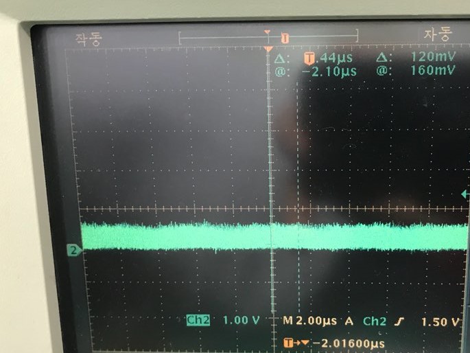
* EMIFB_Clock

  • Hi,
    The applications engineer supporting this device is out of office today and will respond to your inquiry upon his return early next week.
    Thanks
  • Hi,

    What are the full part numbers (or package scribe) of the two devices? I will look into the issue.

    Regards,
    Mark
  • Hi,

    Thank you for your interest.

    Each full part number is 

    OMAPL137BZKBA3

    MT29F4G08ABADAWP-IT

    Thanks.

  • Hi.

    The two devices is not TI EVM.

    that is custom board.

    I just wonder the relationship between "Power-on Sequence" and "OMAPL137"

    Can OMAPL137 be destroyed if power-on sequence is not followed

    It means that 1.2V, 1.8V, and 3.3V are turned on at the same time when the power supply sequence is not followed.

    Thanks.

  • Hi,

    The datasheet states that group 4 (DVDD, USB0_VDDA33, USB1_VDDA33) must be powered-on after the core logic supplies. It goes on further to state that the power supplies can be powered-off in any order as long as the 3.3V supplies do not remain powered with the other supplies unpowered. So there is some concern about having 3.3V on without the core supplied. Refer to 6.3.1 Power-on Sequence and 6.3.2 Power-off Sequence. I believe the reason for the sequence may to avoid unexpected HHV current paths in the IO buffers. I am not sure the impact of enabling all IO supplies simultaneously. Have you measured with a scope the ramp times of the core supplies verses DVDD supplies on both passing and failing boards? Are they identical to each other?

    To me, this description better fits the errata Advisory 2.1.23.

    You have this part number which indicates Silicon Revision 2.0
    OMAPL137BZKBA3
    OMAPL137 B ZKB
    B = Silicon Revision 2.0

    Silicon Revision 2.0 is susceptible to Advisory 2.1.23 - Digital I/O Buffers Age Prematurely
    Revision(s) Affected 2.1 and earlier
    Details The 3.3 V digital I/O buffers on the device exhibit accelerated aging under use conditions with heavy switching activity.
    Refer to the device errata: www.ti.com/.../sprz291

    Do the POH tables under this advisory match the life of the failing part?

    Hope this helps,
    Mark