This thread has been locked.

If you have a related question, please click the "Ask a related question" button in the top right corner. The newly created question will be automatically linked to this question.

AM5726: EMIF Tools - Register Configuration

Part Number: AM5726


Hello,

I have read the sprac36b.pdf and want to do the "EMIF Tools - Register Configuration".

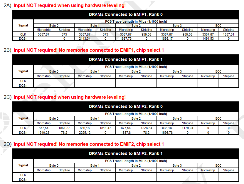
Why I cannot change on scheet one Leveling Techniquie? It is defualt H/W and I can only choose H/W.
Only with the setting "Leveling Techniquie = S/W" it is possible on the next scheet to do changes.

What about Leveling Technique? I can find nothing about that in the datasheet.

The Softwareversion of the sheet is "march 29th 2018 / 2.0.1"

Best Regards

  • I don`t understand why I have to determine microstrip and striplines from CLK and DQSn signals.
    All signals I have to route with 50 Ohm (+/- 5 Ohm).

    In my design I want to use 2 EMIF controller. Each controller has 16 bit DRAM.
    For EMIF1:
    - A1 + A2 : 39,49 mm
    - A3 : 14,02 mm
    - DQ0: 27 mm
    - DQ1: 27 mm
    - DQ2: 25,7 mm
    - DQ3: 19,1 mm

    For EMIF2:
    - A1 + A2 : 36,76 mm
    - A3 : 13,1 mm
    - DQ0: 30 mm
    - DQ1: 33 mm
    - DQ2: 30 mm
    - DQ3: 27 mm

    A1..A3 are signals like ck, ba0..2, a0..15, csn,cas,ras,we,cke,odt.
    -> A1 and A2 are length between chip and DRAM1. A3 Length between DRAM1/3 and DRAM2/4

    Each DQn is composed of (differential) dqs, dqm, 8bit data: all signals have the same length
    How I can write it down to the sheet?
  • Software leveling is not supported for any AM57x device. Only Hardware leveling is supported. Flight times for microstrip and striplines are different, thus these need to be identified in the traces. Just use the CLK and DQS signals, example diagram is given in the Step2-BoardDetails sheet.

    Regards,
    James
  • James thank you for your answer.

    OK, table 2A and table 2C I can ignore it.

    I have to fill out 2B and 2D. The time of flight between microstrip and stripline there are the same on my design because I have it routed to 50 Ohm.

    You say the time of flight of microstrip and stripline are different. If you write this down separately, wouldn't you have to store the impedances as well?

    If I have routed microstrip and striplines to 50 Ohm, I can use one of this cell?

    You said I have to use the both differential CLK and DQS Signals. But I have the length A3 between two DRAM´s. What happens with this length?

    I don`t understand the example in sprac36b.pdf. Look at the attachment below the text. I have entry the letters A-F, is this correct?

  • Kanae, you must fill out the cells individually. Microstrip vs. stripline just refers to the trace segments routed on the outer and inner layers respectively, it has nothing to do with impedance. Use the formulas in the key to determine which trace segment to use. For example, cell C2 should be the total length of the CLK signal from the SoC to the byte2 memory that is on inner layers.

    Regards,
    James
  •  
     Hello James,

    I don't understand the purpose when you differentiate between stripline and microstrip but at the same time don't have to specify the respective impedances.
    I routed my PCB so that both striplines and microstriplines give 50 ohm impedance. So the signal propagation time is always the same if all lines have the same length.

    Now I have a few more questions:
    I use two EMIF controllers with 2 16bit DRAM each. I don't need to fill in 2A and 2C?
    What is the difference between "Rank0 and Rank 1"?

    Regards

  • Yes, fill out sections 2A and 2C (even thought the sheet says not to fill it out for HW leveling). Rank 0 is the memory connected to chip select 0, and Rank 1 is the memory connected to chip select 1.

    Regards,
    James