Hi All,
I would like to ask some questions on DM6437 cache size.
I have found on the first page of SPRS345d that there are:
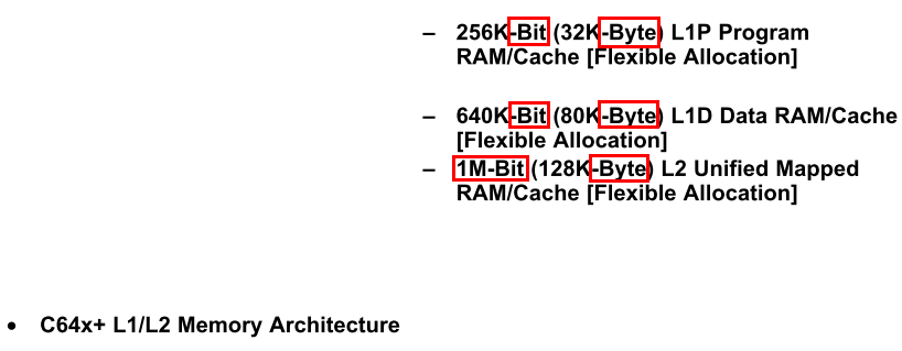
I would like to know why there are two different counting schemes here? We count memory by bytes, sometimes words; but why here bit are also used as counting unit?
How can a single, individual, isolated bit, rather than as part of a larger unit (byte for char, 32 bit for int, etc.), be used in computation? If it is only as a single bit, the only way I can thought of is to to aid conditional judgments in which comparison results like "<", ">", "=" can be stored in as individual bits rather than occupying an entire byte(s), so that space can be saved.
Is it correct or not? Does the programmer or the compiler need to handle these single-bit storage-read operations?
If bit are used in the counting scheme, why not nibble (4 bits)?
Or I am totally wrong here and the use of both bit and byte in the counting here is just for clarification in the sense that the user can infer from this information (256/32=8, 640/80=8, 1M/128K=8) that each "byte" is defined as 8 bits (there can be different definition of byte)?
The size of the byte has historically been hardware dependent and no definitive standards exist that mandate the size.
In RTSC platform setting, the default value(s) for L1D, L1P and L2 cache are all zero-K.
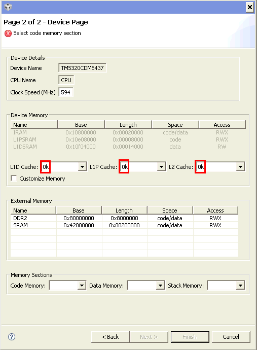
If DM6437 has in its internal 32KB L1P, 80KB L1D and 128KB L2 cache, why are they by default as 0 here? If I am leaving them as 0 unchanged (the documents says they are "flexible allocation", does that mean from 0 to their (L1D, L1P, L2) maximum physical size are all OK? ), will the code still work on the EVM?
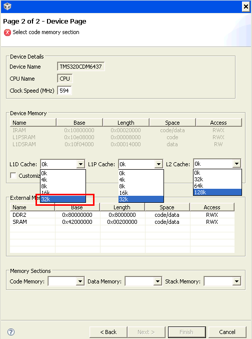
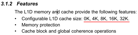
Another setting I have question on is that the drop-down menu for L1D cache allows a maximum of only 32K (byte or bit?), but according to specification DM6437 actually has 80KB "flexible allocation" size. Why here only a maximum of 32KB can be selected?
Could anyone explain these to me?
Sincerely,
Zheng

 ,
,