This thread has been locked.

If you have a related question, please click the "Ask a related question" button in the top right corner. The newly created question will be automatically linked to this question.

Linux/AM3352: GPMC Signal Timing configurations

Part Number: AM3352

Tool/software: Linux

Hello TI,

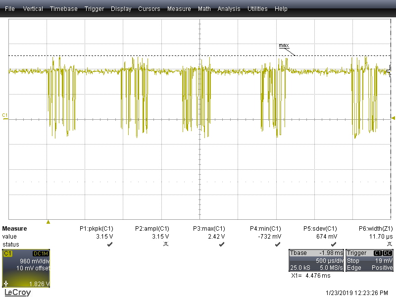
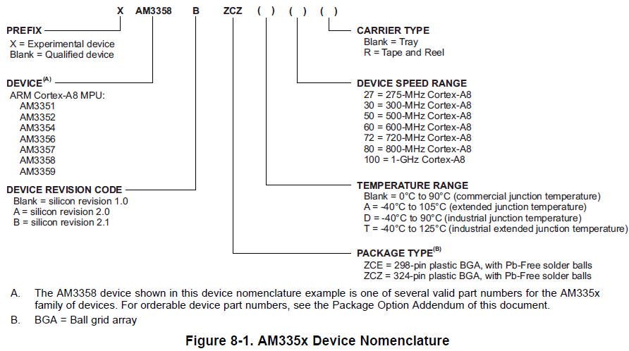
I am using custom AM3352 board with Micron NAND MT29F4G08ABBFA. Here i need to optimize the NAND Performance. As per the  

Tweak NAND device signal timings using AM335x TRM

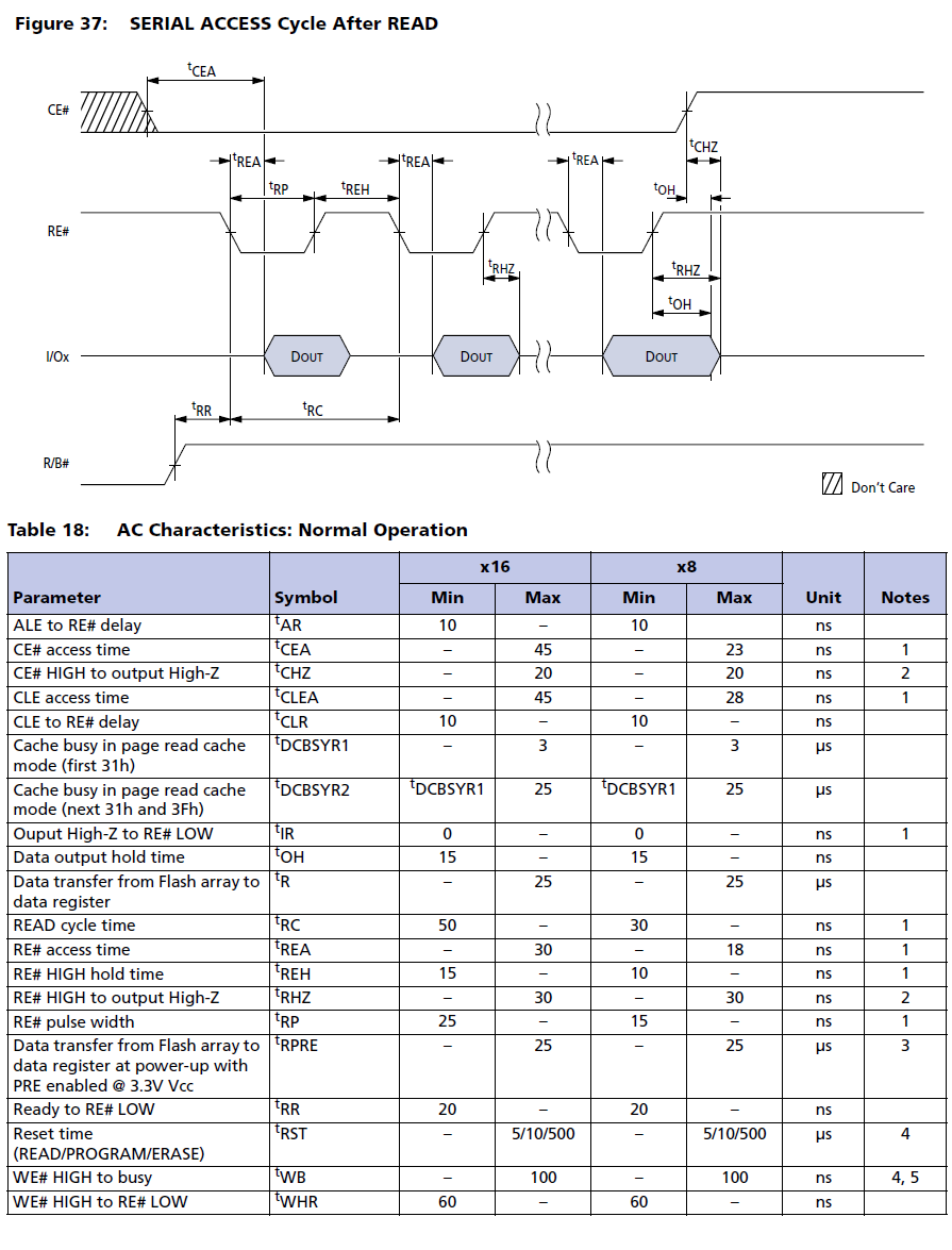
is not easy, Because TRM explains about NOR device signal timings (section 7.1.4.1) And There is no NAND device signal timings. Please guide me how to Tweak NAND device signal timings using Micron NAND MT29F4G08ABBFA data sheet.

(slow while reading from  and writing to) below default gpmc setting i am using (from AM335x-evm.dts)

        gpmc,device-width = <1>;

        gpmc,sync-clk-ps = <0>;

        gpmc,cs-on-ns = <0>;

        gpmc,cs-rd-off-ns = <44>;

        gpmc,cs-wr-off-ns = <44>;

        gpmc,adv-on-ns = <6>;

        gpmc,adv-rd-off-ns = <34>;

        gpmc,adv-wr-off-ns = <44>;

        gpmc,we-on-ns = <0>;

        gpmc,we-off-ns = <40>;

        gpmc,oe-on-ns = <0>;

        gpmc,oe-off-ns = <54>;

        gpmc,access-ns = <64>;

        gpmc,rd-cycle-ns = <82>;

        gpmc,wr-cycle-ns = <82>;

        gpmc,wait-on-read = "true";

        gpmc,wait-on-write = "true";

        gpmc,bus-turnaround-ns = <0>;

        gpmc,cycle2cycle-delay-ns = <0>;

        gpmc,clk-activation-ns = <0>;

        gpmc,wait-monitoring-ns = <0>;

        gpmc,wr-access-ns = <40>;

        gpmc,wr-data-mux-bus-ns = <0>;

  • Hello Govindaraji,

    Due to the US holidays, on this particular E2E thread, our response may get delayed until the week of Jan 2, 2019.

    Warmest Wishes for Happy Holidays and a Happy New Year!

    best regards,
    David Zhou
  • Hi,

    Thanks for your input.

    I gone through those link already. http://processors.wiki.ti.com/index.php/Linux_Core_NAND_User's_Guide  is not helping to tweak nand settings.

    and above forum links are not related to speedup  NAND performance.

    With present AM335x-evm.dts gpmc timings Micron NAND MT29F4G08ABBFA too slow when reading and writing.

    Please guide me how to change the NAND timing settings as per the Micron NAND MT29F4G08ABBFA in dts.

    Even I tried below gpmc timings from AM335X TRM, but no speed increased

            gpmc,cs-on-ns = <0>;  

            gpmc,cs-rd-off-ns = <30>;

            gpmc,cs-wr-off-ns = <30>;

            gpmc,adv-on-ns = <10>;

            gpmc,adv-rd-off-ns = <15>;

            gpmc,adv-wr-off-ns = <15>;

            gpmc,we-on-ns = <25>;

            gpmc,we-off-ns = <50>;

            gpmc,oe-on-ns = <0>;

            gpmc,oe-off-ns = <60>;

            gpmc,access-ns = <30>;

            gpmc,rd-cycle-ns = <30>;

            gpmc,wr-cycle-ns = <30>;

            gpmc,wr-access-ns = <30>;


  • The GPMC module relies on software drivers to adhere to the NAND protocol. Separate stages for command, address, and data phases. Much of the optimization is only possible through software. The GPMC register timings will control the timings of the relative signals during a single phase of NAND access. For example, CS to ALE, to WE signal transitions are controlled by the gpmc registers (eg. gpmc,cs-on-ns = <0>;).

    What software are you using?

    Does this software utilize the Prefetch and Write-Posting Engine? This engine is basically a FIFO and allows the DMA to write to and read from the NAND during a page write/read (after the command and address have been communicated).

    If you scope the NAND signals, you can tell the software overhead apart from the GPMC timings in each phase by looking at CS low period and comparing it to the CS high period (or period of the REn signal during a read).

    You might also be able to profile the code to identify the slowest routines.

    Refer to the following documentation links:
    processors.wiki.ti.com/.../StarterWare_GPMC

    patchwork.kernel.org/.../

    e2e.ti.com/.../315716

    e2e.ti.com/.../481938

    Regards,
    Mark
  • Hi Mark,

    Thanks again for your input.

    i want to do tweek the NAND timings in U-boot. When i try to change the gpmc register in u-boot dts. i couldn't see any changes in speed while reading in u-boot  like => nand read 0x82000000 U-boot or reading from UBI like below

    =>ubi part UBI
    =>ubi check rootfs && ubifsmount ubi0:rootfs
    =>setenv devtype ubi
    =>sysboot ubi 0: any 0x82000000 /boot/initrd.img-4.14.0-0.bpo.2-armmp
    =>sysboot ubi 0: any 0x82000000 /boot/vmlinuz-4.14.0-0.bpo.2-armmp
    =>sysboot ubi 0: any 0x82000000 /boot/dtbs/4.14.0-0.bpo.2-armmp/am335x-asample.dtb

    above commands are mounting & reading bootfiles from UBI partition. average speed of reading is 1.3 MB/s.

    But i found the way to change the gpmc register configs from below link

    as above link as a reference i calculated the gpmc registers using TRM

    NAND_GPMC_CONFIG1

    NAND_GPMC_CONFIG2

    NAND_GPMC_CONFIG3

    NAND_GPMC_CONFIG4

    NAND_GPMC_CONFIG5

    NAND_GPMC_CONFIG6

    NAND_GPMC_CONFIG7

    and updated to u-boot source arch/arm/include/asm/arch-am33xx/mem.h file . By doing this i could see the reading speed increased to 4 MB/s. but this speed is not matching with MT29F4G08ABBFA datasheet. and here 1 page 4 KB read - 25 Micro Seconds.

    Here  i need to know how to calculate the ADVRDOFFTIME, ADVWROFFTIME, OEOFFTIME, OEONTIME, CSRDOFFTIME, CSWROFFTIME, WEONTIME, WEOFFTIME from MT29F4G08ABBFA datasheet?

    In TRM section 7.1.4.1.4 and 7.1.4.1.5 mentioned about GPMC Configuration for Asynchronous read and single write access. but here the AC Characteristics on the Memory Side (Formula) is different from the MT29F4G08ABBFA datasheet. This case how do i calculate the Parameter Name on GPMC side?

  • Hello TI support,

    to clarify the topic a bit more:

    We are currently in product development of a TI AM3352 based measuring device. During boot time optimization we recognized, that the read speed from the above mentioned RAW NAND flash is ~1.3MB/s. Expected is something much higher (> 10x more). The speed is slow from Linux as well as from U-Boot. As U-boot is a bit more strait forward, we checked the sources. Our expectation was that the supported ONFI speed mode is fetched from the NAND and then the GPMC settings are set accordingly by the driver. This seems not to be the case. Instead there are fixed defines for the register settings. Those settings seem to be the same for all Micron FLASH devices, which seems without closer look from my side a bit strange. We got the impression, that basically the ONFI speed mode 0 is used and no speed up is issued to use the supported higher speed mode (ONFI speed mode 3 in our case). So as mentioned, we would have expected the driver to automatically switch to the highest supported speed. As this functionality is not there we seem to have to modify the registers manually, but do not understand how exactly we should calculate the register values from the ONFI timings / timings mentioned in the datasheet. I think the driver would really improve if  the whole settings were auto detected for ONFI compliant NAND (CONFIG_SYS_NAND_ONFI_DETECTION feature in U-Boot). U-boot/drivers/mtd/nand/pxa3xx_nand.c is a very nice example how this is done properly.

    Regards,

    Christian

  • What is the GPMC_FCLK set to? You can increase the GPMC_FCLK and of course adjust the timing parameters accordingly.
  • Hi,

    I am referring AM335x TRM SPRUH73P

    What is the GPMC_FCLK set to?

    • As per TRM Manual GPMC_FCLK set from GPMC_COFIG1_0 bit field(0,1) GPMCFCLKDIVIDER  and value set as  "0h = First rising edge of GPMC_CLK at start access time".

    You can increase the GPMC_FCLK

    • As per TRM, I am using 104 MHz clock full speed,  if i do configure the GPMCFCLKDIVIDER as 0h.

    and of course adjust the timing parameters accordingly.

    • I need to know how to calculate the timing Parameter on GPMC side for 8-bit NAND Flash, but in AM335x TRM given it for 16-bits NOR Flash in section 7.1.4.1

    • Kindly give me the correct procedure to caluate the GPMC parameters for NAND Flash: RdCycleTime, RdAccessTime, CsonTime, CsReadOffTime, AdvOnTime, AdvRdOffTime, OeOnTime, OeOffTime, AccessTime, WrCycleTime, CsOnTime, CsWroffTime, AdvWrOffTime, WeOnTime, WeOffTime.

  • Hi,

    The GPMC interface to NAND flash operates with distinct cycles for command, address, and data.

    NAND Command Latch Cycle:
    Active signals: WRCYCLETIME
    • CSn[i] is controlled by the CSONTIME and CSWROFFTIME
    ! • CLE is controlled by the ADVONTIME and ADVWROFFTIME
    • WE is controlled by the WEONTIME and WEOFFTIME
    • ALE and REn (OEn) are maintained inactive.

    WRCYCLETIME satisfies datasheet requirement
    CSONTIME = 0
    CSWROFFTIME = WRCYCLETIME
    WEONTIME = 0
    WEOFFTIME satisfies datasheet requirement with WRCYCLETIME
    ADVONTIME = 0
    ADVWROFFTIME = WRCYCLETIME

    =-=-
    NAND Address Latch Cycle:
    • CSn is controlled by the CSONTIME and CSWROFFTIME timing parameters.
    ! • ALE is controlled by the ADVONTIME and ADVWROFFTIME timing parameters.
    • WEn is controlled by the WEONTIME and WEOFFTIME timing parameters.
    • CLE and REn (OEn) are maintained inactive.

    ! WRCYCLETIME satisfies datasheet requirement
    CSONTIME = 0
    CSWROFFTIME = WRCYCLETIME
    WEONTIME = 0
    ! WEOFFTIME satisfies datasheet requirement with WRCYCLETIME
    ADVONTIME = 0
    ADVWROFFTIME = WRCYCLETIME

    =-=-
    NAND Data Write Cycle:
    • CSn is controlled by the CSONTIME and CSWROFFTIME timing parameters.
    • WEn is controlled by the WEONTIME and WEOFFTIME timing parameters.
    • ALE, CLE, and REn (OEn) are maintained inactive.

    ! WRCYCLETIME satisfies datasheet requirement
    CSONTIME = 0
    CSWROFFTIME = WRCYCLETIME
    WEONTIME = 0
    ! WEOFFTIME satisfies datasheet requirement with WRCYCLETIME

    =-=-
    NAND Data Read Cycle:
    • CSn is controlled by the CSONTIME and CSRDOFFTIME timing parameters.
    • REn is controlled by the OEONTIME and OEOFFTIME timing parameters
    • REn high-to-data invalid minimum timing value, the RDACCESSTIME

    ! RDCYCLETIME satisfies datasheet requirement
    CSONTIME = 0
    CSRDOFFTIME = RDCYCLETIME
    OEONTIME = 0
    ! OEOFFTIME satisfies datasheet requirement with RDCYCLETIME
    ! RDACCESSTIME optimized for prop delay of REn to NAND, data from NAND


    =-=-=-=-
    Running some quick numbers...

    FCLK # 100MHz = 10ns per cycle
    Each GPMC register bit field specifies a number of FCLK cycles for an event to occur (ie CS low or CS high)

    Take the command latch cycle for example...
    NAND datasheet specifies timing requirements...
    - tCS: setup time CS low before WE high
    - tCH: hold time CS low after WE high
    - tWP: WE low before WE high
    - tALS: setup time ALE low before WE high
    - tALH: hold time ALE low after WE high
    So ideal WRCYCLETIME can be calculated in ns as max((tCS + tCH), (tALS+tALH), (tWP+max(tCH,tALH)))
    And ideal WEOFFTIME (in ns) can be calculated as tWP
    To get values for the register bit fields, divide by the FCLK period (10ns) and make all the events relative to StartCycleTime, where CS first goes low starting the cycle.

    You then need to add margins to these timings to account for the switching characteristics of the GPMC peripheral in silicon. There will be slight timing variations between devices.
    The datasheet provides switching characteristics of these signals in two ways:
    1) From internal GPMC_FCLK cycle to a signal transition on the pins (Table 7-26, ex. Delay time, output chip select gpmc_csn[x] generation from internal functional clock GPMC_FCLK)
    2) From one signal transition to the next at the pins (Table 7-28, ex. Delay time, output chip select gpmc_csn[x](13) valid to output write enable gpmc_wen valid).

    In general, adding margin of one FCLK cycle should be sufficient.

    So for the MT29F4G08 datasheet that I found...
    tCS = 35ns
    tCH = 10ns
    tWP = 25ns
    tALS = 25ns
    tALH = 10ns

    So we need a CS low period of at least 45ns (5 FCLK cycles will give us ~50ns)
    tWP and tALS are smaller than tCS, so we'll satisfy their setup time requirements of 25ns if we set WE low at the beginning of the cycle with CSn.
    CSONTIME = 0
    WEONTIME = 0
    ADVONTIME = 0
    WEOFFTIME = 4 (4 FCLK cycles give about 40ns > 35ns - datasheet table may force us to add more margin)
    WRCYCLETIME = 6 (only need 10ns of hold time, but would have no or negative margin - give 20ns for margin)
    CSWROFFTIME = 6
    ADVWROFFTIME = 6
    That leaves us with a CS low period of about 60ns, which is greater than the 45ns min.

    Follow this procedure for address latch, write data, and read data cycles.
    You will end up using the same register settings for all cycles, so if one forces you to use slower timings, then it drives the timings for all cycles.

    For a read cycle, consider also the propagation delay to and from the NAND memory and the output delay of the NAND device so you give enough margin for the ReadAccessTime.

    When you populate the GPMC timings into the DTS, it uses nanoseconds instead of GPMC FCLK cycles. So the DTS you have attached actually looks pretty fair.
    There may be other things slowing down the access like non-posted writes (waiting for confirmation from the NAND), or using the WAIT signals to stall the bus.

    The TRM has lots of details. Check out 7.1.2.3.12 NAND Access Description, specifically 7.1.2.3.12.2 NAND Device-Ready Pin.

    Did this exercise help you to understand the process of optimizing the GPMC timings?
    There will likely be some trial and error involved also.

    Regards,
    Mark
  • Hi Mark,

    Thank you for your Valuable reply,

    From your Input i did the calculation of gpmc parameters using nand MT29F4G08ABBFA

    CSONTIME = 0

    CSWROFFTIME = WRCYCLETIME

    WEONTIME = 0

    ADVONTIME = 0

    ADVWROFFTIME = WRCYCLETIME

    CSRDOFFTIME = RDCYCLETIME

    OEONTIME = 0

    FCLK # 100MHz = 10ns per cycle

    for the MT29F4G08ABBFA datasheet that I found...
    tCS = 25ns
    tCH = 5ns
    tWP = 15ns
    tALS = 10ns
    tALH = 5ns

    So we have CS low period is 30ns (3 FCLK cycles will give us 30ns)

    WRCYCLETIME can be calculated in ns as max((tCS + tCH), (tALS+tALH), (tWP+max(tCH,tALH))) is 30ns

    And ideal WEOFFTIME (in ns) can be calculated as tWP is 15ns

    CSONTIME = 0
    WEONTIME = 0
    ADVONTIME = 0
    WEOFFTIME = 2 (2 FCLK cycles give about  tWP -> 15ns)
    WRCYCLETIME = 4 (10ns of hold time)
    CSWROFFTIME = 4
    ADVWROFFTIME = 4
    Here CS low period is about 40ns, which is greater than the 30ns min.

    And For ReadAccessTime

    #define OEONTIME_NAND 0x0 /* RE# on time */

    #define OEOFFTIME_NAND 0x4 /* RE# off time */ /* AccessTime + 1Cycle = round max(tCE) + 1 Cycle = 30 ns + 1 Cycle = 3 + 1 = 4 */ /* Calculated from TRM Table 7-43 */

    #define RDACCESSTIME_NAND 0x4 /* sampling point for read */

    #define RDCYCLETIME_NAND 0x5 /* complete read time */

    #define CSRDOFFTIME_NAND RDCYCLETIME_NAND /* CE# off for read */

    #define ADVRDOFFTIME 0 /* this Value not clear for me from the TRM Table 7-43.*/

    From gpmc parameters i got these gpmc configs

    gpmc regs config1:     801

    gpmc regs config2:   40500

    gpmc regs config3:   40100

    gpmc regs config4: 2000280

    gpmc regs config5: 1040405

    gpmc regs config6: 4000081

    gpmc regs config7:     C44

    By using above values in u-boot patch

    with this u-boot NAND Reads 4 MB/s and 1 page (4096 Bytes) read  is 4 KB / mile Seconds.

    Where in datasheet NAND Read per page(4096 +256 Bytes) 25 Micro Seconds. which is equivalent to 6.4 MB/ mile Seconds.

    To achieve this NAND Read Speed which gpmc configurations have to change?

  • Hi Govindaraji,

    Can you confirm that the WAIT/READY pin is not asserted and causing a delay during boot?

    The source code for the NAND U-boot mode is on git: git.ti.com/.../omap_gpmc.c

    You should be able to boot faster if you have CONFIG_NAND_OMAP_GPMC_PREFETCH defined when building. Can you try it?

    Refer to these E2E threads and wiki...

    e2e.ti.com/.../2184974

    e2e.ti.com/.../348712

    processors.wiki.ti.com/.../Linux_Core_NAND_User's_Guide

    Regards,
    Mark
  • Hi Mark,

    I set WAITPINSELECT =0 in the NAND_GPMC_CONFIG1.

    and i am using CONFIG_NAND_OMAP_GPMC_PREFETCH in u-boot configuration.

    but i am getting 4 MB/ s in u-boot ubi vmlinuz read.

    but From MT29F4G08, theoritcal calcuation of NAND read speed per page comes to 25 MB/ s.

    reading file from ubifs getting more delay between two pages, and how reduce the delay between page read.
  • Hi Govindaraji,

    Can you capture a waveform of the accesses with an oscilloscope or logic analyzer?

    It sounds like the GPMC parameters are optimized, and you are using the faster boot mode (PREFETCH). I just wonder if the signals are coming out as expected. Or perhaps we would see large delays between the NAND accesses on the GPMC bus.

    I'm more focused on hardware, so I do not know the maximum NAND boot bandwidth.

    Is it possible to perform NAND accesses after boot to compare the bandwidths when you have more control over the software?

    Regards,
    Mark
  • From OScilloscope we capured the NAND page read time ~400 Micro seconds

    and delay between the page read is varying ~600 - 800 Micro seconds.

    When ubifs read from u-boot, we got above waveform.

    and u-boot raw nand read waveform is below one. here page read time is ~400 Micro Seconds, but delay is less compared to ubifs read from u-boot

    In both case page read time is ~400 Micro second. but ap per NAND Data sheet 155 Micro seconds

    delay between page read tRCBSY is 25 Micro seconds. but in raw nand read delay between pages is goes ~250 Micro seconds

    Here, i dont know how proceed further. help me to do further.

    Thanks & regards

    Govind.

  • Give a calculation is know about GPMC parameters RDACCESSTIME and WEOFFTIME
    In TRM I read enough i guess, but i couldn't connect with date sheet values.
  • Hi,

    WEOFFTIME needs to satisfy tWP from the device datasheet for command, address, and write cycles. WE can be low at the start of the cycle (when CS goes low). The datasheet has tWP = 25ns, so I actually think WEOFFTIME = 3 (30ns) would have achieved this with margin.

    =-=-=-=-

    RDACCESSTIME is the FCLK rise edge corresponding to when the GPMC latches the read data. It needs to give enough time for the read access time to occur.

    But the read cycle occurs after a command and multiple address cycles, so the start of the read access cycle is when the CS goes low after second page read cycle command is given.

    RDACCESSTIME = tCEA = 45 (so 50)

    Work backwards from there so you know when to drive low the nRE signal.

    tREA = 30ns (nRE must be low 30ns before RDACCESSTIME)

    nRE is controlled by OEONTIME and OEOFFTIME.

    RDACCESSTIME = 5 should work

    OEONTIME = 1 or 2

    OEOFFTIME = 6 (satisfies nRE low pulse: tRP = 25, so 30)

    In the case of this serial access, multiple reads are performed each read cycle. You can configure READMULTIPLE, ATTACHEDDEVICEPAGELENGTH, and PAGEBURSTACCESSTIME parameters to get an asynchronous page read to occur.

    Regards,
    Mark

  • Hi Mark,

    Thanks for your valuable Input

    from above conversations I had below gpmc parameters values

    CSONTIME=0

    CSRDOFFTIME=3

    CSWROFFTIME=3

    OEONTIME=1

    OEOFFTIME=2

    ADVONTIME=0

    ADVRDOFFTIME=3

    ADVWROFFTIME=3

    RDCYCLETIME=3

    WRCYCLETIME=3

    WEONTIME=0

    WEOFFTIME=2

    RDACCESSTIME=3

    WRACCESSTIME=0

    u-boot gpmc config values are modified for MT29F4G08ABBFA

    M_NAND_GPMC_CONFIG2 0x00030300

    M_NAND_GPMC_CONFIG3 0x00030300

    M_NAND_GPMC_CONFIG4 0x02000201

    M_NAND_GPMC_CONFIG5 0x00030303

    M_NAND_GPMC_CONFIG6 0x000000C0


    and Linx DTS GPMC parameter values are

    gpmc,cs-on-ns = <0>;

    gpmc,cs-rd-off-ns = <30>;

    gpmc,cs-wr-off-ns = <30>;

    gpmc,adv-on-ns = <0>;

    gpmc,adv-rd-off-ns = <30>;

    gpmc,adv-wr-off-ns = <30>;

    gpmc,we-on-ns = <0>;

    gpmc,we-off-ns = <15>;

    gpmc,oe-on-ns = <1>;

    gpmc,oe-off-ns = <15>;

    gpmc,access-ns = <30>;

    gpmc,wr-access-ns = <0>;

    gpmc,rd-cycle-ns = <30>;

    gpmc,wr-cycle-ns = <30>;


    GPMC Parameter calculation is not mentioned anywhere for NAND device . If such document available then, easy to integrate the new nand gpmc configuration in u-boot and Linux.
  • Hi Govindaraji,

    Thanks for sharing your GPMC register settings and resulting dts.

    We are working to address this gap in documentation, but more focused on GPMC to FPGA interfaces.

    Right now, I think the best two pieces of information for GPMC to NAND interfaces are these...

    processors.wiki.ti.com/.../Linux_Core_NAND_User's_Guide
    - Examples of NAND parts are present, but GPMC register values are not shown

    bitbucket.itg.ti.com/.../gpmc-nand.txt
    - Has example for an AM33xx board with dts values

    With your latest GPMC configuration, are you seeing improved boot bandwidth?

    Regards,
    Mark
  • Hi Mark,

    below is the raw nand read results i got in linux

    AM335x MT29F4G08 DTS configs with rootflags=bulk_read,chk_data_crc

    [2019-02-11 16:45:11] $ sudo dd if=/dev/mtd8 of=/dev/null bs=2M count=8
    [2019-02-11 16:45:25] [sudo] password for user:
    [2019-02-11 16:45:28] 8+0 records in
    [2019-02-11 16:45:28] 8+0 records out
    [2019-02-11 16:45:28] 16777216 bytes (17 MB) copied, 0.960006 s, 17.5 MB/s

    I have to check the ubifs read from linux and from U-boot Ubifs read improved to 4 MB/s, but here we are looking some more improvement

    and how can i pass UBIFS Options like bulk_read,chk_data_crc in u-boot?
  • Hi Govindaraji,

    I reached out to some software folks about this issue.

    Can you confirm the full package suffix of your AM3352 device? We want to make sure it is not speed limited, preventing it from operating at full gigahertz speeds. See table below.

    It was also recommended to use the falcon mode which will skip the U-Boot stage, speeding up the boot process...

    I am still waiting to hear back about the ability to pass UBIFS options to u-boot.

    Regards,
    Mark

  • Hi Mark,

    Thank you for your Input, and below is package suffix of our device

    Sitara AM3354BZCZA100

    And our device speed range is 1-GHz Cortex-A8.

    Can you please post some Links about falcon mode.

    Thanks and Regards,

    Govind.

  • Govind,

    Have you made the GPMC timing changes in U-Boot as well? This is done in the arch/arm/dts/am335x-evm.dts file similar to Linux.

    Thank you.
  • Hi RonB,

    the nand gpmc dts configuration not using in gpmc drivers/mtd/nand/omap_gpmc.c board_nand_init () or from board.c function call gpmc_init(); arch/arm/mach-omap2/mem-common.c using nand gpmc dts configuration.

    but from my understanding, nand gpmc is configured only by ./arch/arm/mach-omap2/mem-common.c gpmc_init(); using M_NAND_GPMC_CONFIG{1-7}.

    If anything available to integrate the nand gpmc dts configuration, please let me i will try that one also.

    Thanks & regards,

    Govind.

  • Hi Mark,

    Thanks for the link provided for falcon mode, And i will experiment and let you know it.

    Any Update on the U-boot UBIFS read with option bulk_read?

    Thanks and regards,
    Govind.
  • Hi Govind,

    Passing along information from Kemal on this matter...

    There is also falcon mode documented in <Processor SDK>/board-support/u-boot-<version>/board/ti/am335x/README file.

    Kemal tried NAND falcon mode on AM335x GP EVM and it works. You just need to change the default 0x2000 to default 0x40000 in <Processor SDK>/board-support/u-boot-<version>/cmd/Kconfig to match the CMD_SPL_WRITE_SIZE of NAND.u-boot-spl-os 0x00080000 0x00100000 0 and enter => setenv os_boot 1 in U-Boot console to activate the Falcon mode. You can later stop the booting by holding 'c' pressed while the U-Boot SPL is loading if you want to enter in U-Boot console.

    You can pass the bulk_read,chk_data_crc to the Kernel, but I am not sure how you can pass there arguments in U-Boot. You can check this thread to see how you can mount ubifs in U-Boot.

    Regards,
    Mark

  • Hello Govindaraji,

    Was you able to test the NAND falcon mode on your board?

    Best regards,
    Kemal