This thread has been locked.

If you have a related question, please click the "Ask a related question" button in the top right corner. The newly created question will be automatically linked to this question.

AM3352: AM3352BZCEA30 + TPS65910 PMIC Start up Issue

Part Number: AM3352
Other Parts Discussed in Thread: TPS65910, , TPS65910A

Hi,

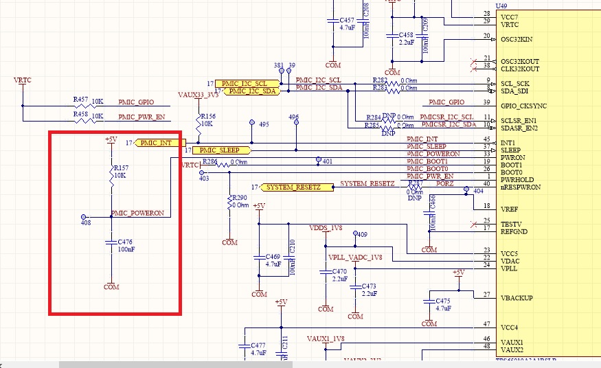
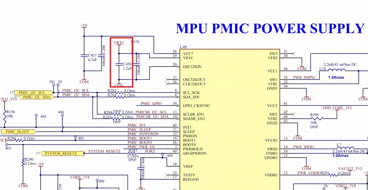
Related to TPS65910 PMIS start up and all the output voltage generation, in some of the boards, VRTC remains around 0.9V for other boards it works fine and VRTC = 1.8V. We had done below listed experiements.

1. On the VRTC pin of TPS65910 PMIC, one bulk capacitor of 2.2uF was mounted which we had removed so only 0.1uF capacitor on VRTC is there . In this case, most of the boards work fine but still in some of the boards, we are facing start up issues.

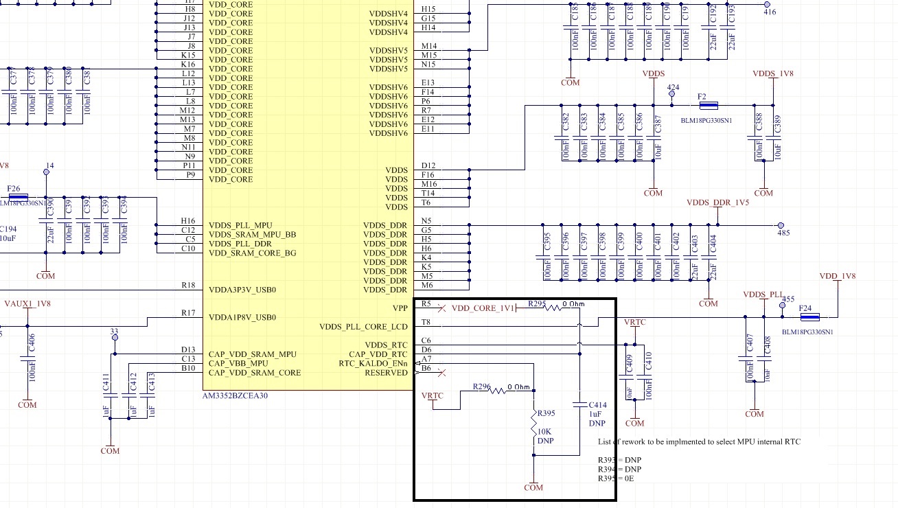
2.  In our application , we are not use low power or sleep mode of Microprocessor. and in the below schematic, we had done the rework as mentioned below and start up issue is resolved. We had gone through Technical reference manual of AM3352 Section No. 8.1.4.3.6 and change to RTC Internal RTC LDO . Kindly check and confirm the rework or any changes required if any.

List of Rework from current circuit: R296 = Do Not Mount, R395 = 10K , C414 = 1uF, R295 =Do Not Mount

Please help us to provide more information on this so that this issue can be avoided in Production.

Regards,

Krushang Gandhi

  • Krushang,

    The normal boot sequence for TPS65910A plus AM335x looks roughly like this:

    1. When the PMIC is powered, it initially powers up only VRTC.
    2. The AM335x asserts PMIC_PWR_EN.
    3. The PMIC then ramps up the rest of the rails.

    The problem in your original configuration is that the RTC needs two voltages, 1.8V and 1.1V.  For the 1.1V rail, you can either generate that internally using the LDO (RTC_KALDO_ENn = 0) or supply that voltage externally (RTC_KALDO_ENn = 1).  Your board was initially configured to supply the voltage externally.  However, you'll notice that in step 1 of the sequence I mentioned above, only 1.8V is being supplied, i.e. the RTC peripheral has no 1.1V rail.  This is violating the power sequencing requirements of the device.  Without the 1.1V rail, we get unexpected power paths, etc.

    The reason why it sometimes fails is because the amount of current on the 1.8V rail is much higher in this configuration (i.e. due to unexpected power paths).  When the current consumption is too high this causes the rail to droop way low which is either preventing PMIC_PWR_EN from asserting, or perhaps the PMIC itself is seeing that it is out of regulation and not starting up.

    The changes you've described will have the RTC LDO enabled at power-up.  This avoids the unexpected power paths, and meets the power-up requirements of the AM335x.  So in short, I believe the changes you've made are appropriate and I expect them to be reliable for mass production.  Hopefully this clears up some of the confusion and allows you to move forward.

    Best regards,
    Brad

  • Brad,

    Thanks for providing technical description and confirming hardware changes.

    I had one more query related to TPS65910 PMIC "PWRON" Input. As per Technical reference manual, it says to connect with AM3352 . However, in the our design we had put RC network as per below image. Also please let me know if any other care or connection changes needs to be done at the TPS65910 PMIC Side.

    Kindly share yours inputs for same.

    Thanks ,

    Krushang Gandhi

  • Krushang Gandhi said:
    I had one more query related to TPS65910 PMIC "PWRON" Input. As per Technical reference manual, it says to connect with AM3352

    Where did you see that?  In the app note "TPS65910Ax User's Guide for AM335x Processors" it is shown as being connected to a push button.

    In any case, this signal functions in an active-low capacity, so your configuration looks like it would not utilize this signal, which is fine.