This thread has been locked.

If you have a related question, please click the "Ask a related question" button in the top right corner. The newly created question will be automatically linked to this question.

TDA2E: A pin cannot be used as a normal GPIO

Part Number: TDA2E

TDA's software driver has affected the SD card power supply to remain at 3.3V, because our current hardware design: Y9 pin (sdwp) on the TDA chip is used as the SD card power driver

Our software engineers feedback that sdwp has been occupied by the mmc1 software driver, and the Y9 pin cannot be used as a normal GPIO to control the power of the SD card.
How do we solve this problem?

PS: Our SD card only needs 3.3V running mode

  • Hi Feng,

    Can you please post a diagram of your hardware setup for better understanding?

    Also, one question in advance - is your PCB layout forzen? I.e. you are no longer allowed to make changes to the design?

    Thanks,

    Stan

  • Hi,Stan

    Yes, we are not going to change the PCB layout

    The hardware diagram is as follows

  • The pin mux is typically done outside any driver - in the SBL bootloader. Therefore, you should be able to change Y9 to GPIO w/o driver even knows it. This can be done in the device tree (.dts) file which SBL will reflect in the CTRL_CORE_PAD_MMC1_SDWP SoC register. There are many articles on TI.com and posts in this forum how to do this.
    On the other hand, the MMC driver will continue (if was enabled) to monitor the Write-Protect (WP) pin, thus this functionality may need to be disabled in the driver. I'm a hardware engineer and I don't know how MMC driver was implemented, but since WP is an optional feature, this should be possible in the driver.
    Regards,
    Stan
  • We has tried the following steps:

    Configure the kernel's pinmux output to pull up by default, but after the file system is running, we check the status of the gpio and find that this pin attribute becomes the input drop-down.

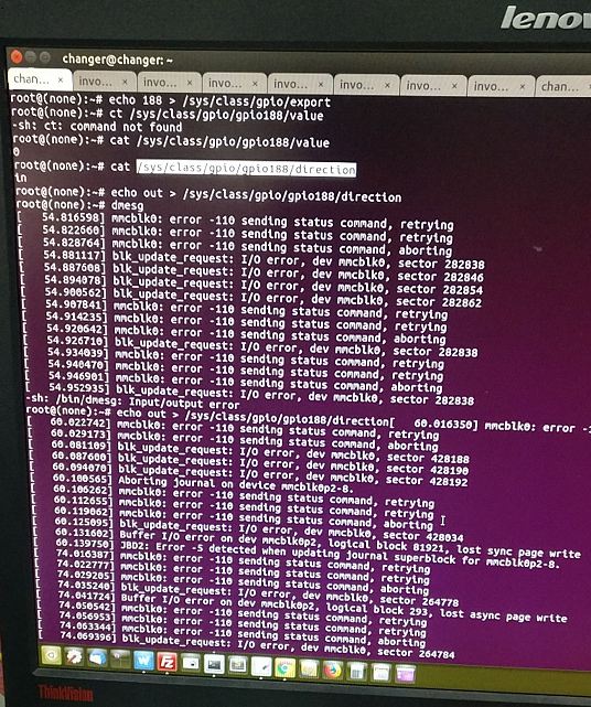
    Then the next step, when we tries to manually change the direction property of the gpio, the mmc software driver will report some errors.(As shown below)

    We analyze the mmc driver and the gpio driver is occupied.

    How to solve this problem in software?

  • Hi,

    Please check your device tree.
    Most likely, only the cd-gpio is described. wp-gpio is not described.

    You should be able to use the MMC1_SDWP pad in the GPIO mode 0x14 which will make it connect to the GPIO6_28 line.
    Refer TRM (CTRL_CORE_PAD_MMC1_SDWP)
    By default, both CD and WP pads are configured by u-boot to be in the muxmode 0x14 which will be the GPIO mode.


    Also, If my understanding is correct, GPIO6_28 should be registered as 32 * 6 + 28 = 220 in the /sys/class/gpio subsystem.
    So you should try to change that.


    Regards,
    Nikhil D