This thread has been locked.

If you have a related question, please click the "Ask a related question" button in the top right corner. The newly created question will be automatically linked to this question.

RTOS/TMDSIDK437X: About motor_control project using tamagawa encoder

Genius 5840 points
Part Number: TMDSIDK437X
Other Parts Discussed in Thread: SYSBIOS,

Tool/software: TI-RTOS

Hello.

I'm evaluating motor_control project.

If I use tamagawa encoder in this project,is the project running method correct only by the below procedure?

1. In Project properties->Build->GNU Compiler->Symbols,  move ENDAT_ENCODER from Define Symbols to Undefine Symbols,

    and move TAMAGAWA_ENCODER from Undefine Symbols to Define Symbols

2.Rebuild Project 

My tamagawa encoder works well in default tamagawa_diagnostic project.

But it doesn't work in motor_control project following the above procedure. 

Regares,

U-SK

  • Hi,

    Can you confirm that you are using the same hardware connections as when you run the tamagawa_diagnostic project?

    Your actions in #1 seem correct. I am checking with the development team on this.

    Jason Reeder

  • Hi Jason,

    Thank you for your reply.

    Can you confirm that you are using the same hardware connections as when you run the tamagawa_diagnostic project?

    ->Yes, it is same hardware connections.

       motor and encoder completely doesn't work in motor_control project.

       It seems not to exrcute PwmISR() function in foc.c.

    Because there was following warning , I added prototype declaration, and these warning is dissapeared.

    But result has not changed.

    warning:

    implicit declaration of function 'pow' [-Wimplicit-function-declaration] tamagawa.c /motor_control_AM437x_arm/tamagawa line 76 C/C++ Problem
    implicit declaration of function 'pwmADCAppInit' [-Wimplicit-function-declaration] main.c /motor_control_AM437x_arm line 172 C/C++ Problem
    implicit declaration of function 'tamagawa_pruss_load_run_fw' [-Wimplicit-function-declaration] tamagawa.c /motor_control_AM437x_arm/tamagawa line 67 C/C++ Problem

    I added:

    "#include <math.h>" in tamagawa.c
    "extern void pwmADCAppInit();" in main.c
    "extern void tamagawa_pruss_load_run_fw();"in tamagawa.c

    And other warnings existing now as below.

    'tamagawa_display_menu' defined but not used [-Wunused-function] tamagawa_app.c /motor_control_AM437x_arm/tamagawa line 252 C/C++ Problem
    'tamagawa_display_result' defined but not used [-Wunused-function] tamagawa_app.c /motor_control_AM437x_arm/tamagawa line 115 C/C++ Problem
    'tamagawa_get_command' defined but not used [-Wunused-function] tamagawa_app.c /motor_control_AM437x_arm/tamagawa line 184 C/C++ Problem
    unused variable 'eb' [-Wunused-variable] main.c /motor_control_AM437x_arm line 137 C/C++ Problem
    variable 'poc_auto_status' set but not used [-Wunused-but-set-variable] main.c /motor_control_AM437x_arm line 139 C/C++ Problem

    Is there anything else I need to modify?

    Regards,

    U-SK

  • Hi,

    Do you have any updates about my question?
    Regards,

    U-SK
  • Hi,

    Yes, our development team is replicating the Tamagawa setup in the lab and I expect that we will have a resolution soon.

    I will let you know as soon as we have some results.

    Jason Reeder

  • A few questions to help us move forward:

    Jason Reeder

  • From the ROV perspective we were mainly looking for:

    • Trace for each task. Where exactly the application is currently running
    • If there is any stack overflow for the application or any of the tasks

    Jason Reeder

  • Hi Jason,

    Thank you for your reply.

    >Is the application crashing at some point, or hung in a loop?

    ->When I suspended, the application stops at any line in Task_allBlockedFunction() or Task_schedule() in Task.c.

    >Does the application never reach PwmISR() or does it reach PwmISR() and then crash?

    ->The application never reach PwmISR(). But Pwm ISR seems to be generated.

    >Can you see any errors in the sysbios ROV (processors.wiki.ti.com/.../Runtime_Object_View_(ROV))

    ->When I use ROV at first, I could not connect ROV, so removed the Program.sectionsExclude line in cfg file according to other E2E thread,  and connection is successed .

    ROV window is as below.

    There seems to be no errors, but some graphs is not appeared.

    Could you tell me also how to display any graphs?

    Regards,

    U-SK

  • Hi,

    The development team was able to root cause the issue that was preventing the PwmISR() function from getting called. The root cause of the issue is that the PRU that handles the on-chip ADC triggering was waiting on an event to be generated by the other PRU. In the EnDat case, the other PRU was triggering and clearing the event. In the Tamagawa case, the PRU doesn't trigger or clear this event so the ADC PRU does not need to wait on it.

    You will need to comment out (using a semicolon), or remove, the ENDAT_TRIGGER_GENERATE definition at the top of the pru_adc_sampling.asm file. This file can be found in:

    PRU-ICSS-Industrial_Drives_01.00.02.00\interfaces\pru_onchip_adc_sampling\firmware\pru_adc_sampling.asm

    There is a batch script in the 'firmware' folder to rebuild the firmware.

    Once the definition is removed and the firmware is rebuilt, you should see the PwmISR() being entered periodically. Please let me know if this is not the case.

    Jason Reeder

  • Hi Jason,

    Thank you for your reply.
    I modified source code and rebuild pru_adc_sampling firmware as following procedure,
    unfortunately, result was not changed.

    1.Install ti-cgt-pru_2.3.1

    2.Modify build_pru_adc_sampling.bat as follows
    line1 : set PRU_C_COMPILER_PATH=C:\ti\ccsv8\tools\compiler\ti-cgt-pru_2.3.1
    line6: C:\ti\PRU-ICSS-Industrial_Drives_01.00.02.03\examples\tools\bin2header\bin2header.exe pru_adc_sampling.b00 pru_adc_sampling_bin.h SMARTADCPRU1 4
    →there was an error because bin2header.exe path of line 6 was invalid.

    3.Copy all header files in below directory to same directory as pru_adc_sampling.asm
    C:\ti\PRU-ICSS-Industrial_Drives_01.00.02.03\interfaces\include\firmware\am437x
    →There were errors because these file that should be included in pru_adc_sampling.asm was nothing in current directory.

    4.Execute build_pru_adc_sampling.bat in command prompt and confirm that pru_adc_sampling_bin.h is updated.

    Are above rebuild procedure correct?
    Regards,

    U-SK
  • Those build procedures look correct for the PRU firmware.

    One more change may be necessary in the tamagawa.c file (C:\TI\PRU-ICSS-Industrial_Drives_01.00.02.03\interfaces\tamagawa_receiver\driver\tamagawa.c). Can you please try moving the PRUICSS_pruIntcInit() function to the end of the function? It should look something like this when you've made the change:

    void motorControlICSSInit(PRUICSS_Handle *pruIcssHandle) {
    tamagawa_adapter_pinmux();

    tamagawa_pruss_init();

    *pruIcssHandle = getPruIcssHandle();
    PRUICSS_pruIntcInit(*pruIcssHandle, &pruss0_intc_initdata);
    }

    Jason Reeder
  • Hi Jason,

    Thank you for your reply.
    I also modified tamagawa.c as you mentioned, but result was not changed.
    Is there anything else I should review?

    Regards,
    U-SK
  • For debugging, few things to check would be
    1) Verify that the “pruIcssHandle” variable in initialized before it is sent to the PRUICSS_pruIntcInit() function.
    2) Halt the ICSS0-PRU1 and manually step through the code. Is it always stuck at the same instruction?
    3) Check if the status of bit 7 in the PRU_ICSS_INTC_SRSR0 register for ICSS0
    4) Check the comparator status for CMP1 and CMP2. [bit 2 and bit 3] of PRU_ICSS_IEP_TMR_CMP_STS
  • Hi kshin,

    Thank you for your reply.

    I described answers to your question as below.

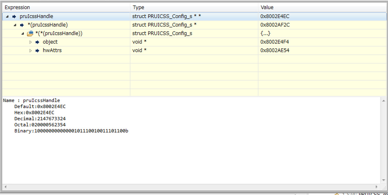
    1)      Verify that the “pruIcssHandle” variable in initialized before it is sent to the PRUICSS_pruIntcInit() function.

    →This is the capture when program is suspended at the breakpoint of PRUICSS_pruIntcInit() line in motorControlICSSInit() function.

    2)      Halt the ICSS0-PRU1 and manually step through the code. Is it always stuck at the same instruction?

    →Yes, ICSS0-PRU1 went back and forth between the addressed between 0x04 and 0x08 respectively as below capture.

    3)      Check if the status of bit 7 in the PRU_ICSS_INTC_SRSR0 register for ICSS0

    →When I answering 2), PRU_ICSS_INTC_SRSR0 register value is 0x00000060, so bit7 is 0.

    4)      Check the comparator status for CMP1 and CMP2. [bit 2 and bit 3] of PRU_ICSS_IEP_TMR_CMP_STS

    →When answering 2), PRU_ICSS_IEP_TMR_CMP_STS register value is 0x00000000.

    Regards,

    U-SK

  • Hi,

    This assembly code you are showing the PRU stuck in corresponds to the FOC_IDLE loop in the pru_adc_sampling.asm file. Here is the corresponds assembly in the file:

    FOC_IDLE:

    ; Wait till host is ready, Indicate via FOC_CONTROL_OFFSET
    LBCO &TEMP_REG_1.b0, PRU1_DMEM, FOC_CONTROL_OFFSET, 1
    QBNE FOC_IDLE, TEMP_REG_1.b0, FOC_CONTROL_ENABLE

    This means that the PRU is constantly reading it's local memory (DMEM + 0x50) and expecting a 1 to be there which corresponds to an enable flag that should be set from the Arm core. Without this the PRU never begins reading ADC data and never triggers the Pwm_ISR() function.

    The Arm core should set this bit at the end of the pwmADCAppInit function in the foc.c file:

    // Enable in PRU to generate FOC events
    #ifdef    ADC_SDDF
        sd_enable_triggered(sd);
    #else
       p_mem_foc_params->control = FOC_CONTROL_ENABLE;
    #endif
    

    This should happen as long as ADC_SDDF isn't defined. Can you confirm that ADC_SDDF is NOT defined. And then also check to make sure that the Arm core is running this line of code?

    Jason Reeder

  • Hi Jason,

    Thank you for your reply.

    ADC_SDDF is not defined.
    And I confirmed "p_mem_foc_params→control" parameter, it was 1.
    So the code you mentioned should be executed.

    Is there a way to check addresses of "DMEM + 0x50" PRU is reading?

    I attached pru_adc_sampling_bin.h.

    Is my result of rebuild correct?

    pru_adc_sampling_bin.h


    Regards,
    U-SK

  • Hi,

    It appears like there is an update we need to add to the batch script used for rebuilding the PRU firmware that will define the PRU being built for as ICSS1. Please use the attached build script to build the firmware and let me know if this fixes your issue.

    Jason Reeder

    /cfs-file/__key/communityserver-discussions-components-files/791/build_5F00_pru_5F00_adc_5F00_sampling.bat

  • Hi Jason,

    Thank you for your reply.
    I applied script file you sent, then I saw PWM ISR!
    But motor doesn't run well in closed loop and position data seems not to be gotten.
    motor runs well in open loop.

    Are there any points to check?
    I'll try to debug detail tomorrow.

    Regards,
    U-SK
  • Hi Jason,

    I debugged and checked some codes.
    getEncoderAngle() seems to run well and returns 17bit value.
    But ElectricalThetaCalculate() and speed calculation seems to be wrong.

    My encoder(TS5668N43) gives 17bit value(0-131071).
    So I modified as below.

    int ed_step = 131072;
    int ed_turn_res = 17;

    Is above right?

    And my motor's power source specifications is DC48V.
    So I need to modify some defined value.

    Power source of TMDSIDK437x I'm using is also DC24V power supply when using DC48V Motor.

    If we use the motor that power supply voltage and other specifications are different from BLY171D-24V-400,
    what parameter should I change in motor_control project?

    Regards,
    U-SK
  • Hi U-SK
    I wanted to let you know that Jason is out of office till Feb 18, so responses on this thread will be delayed.
    Good to see some progress from the last issue.
    We will follow up on the new issue around closing the loop and no position data etc, early next week.
    Sorry for the delay

    Regards
    Mukul
  • Hi,

    Your ed_step and ed_turn_res number look correct to me.

    foc.h has some motor specific constants at the top of the file but I'm not sure if they are used anywhere in our sensored example.

    After changing the ed_step and ed_turn_res variables to the correct values, are you able to run closed-loop control with the Tamagawa encoder?

    Jason Reeder
  • Hi Jason,

    Thank you for your reply.
    The closed loop did not run after modifying ed_step and ed_turn_res.
    But position data displayed in terminal is good after modifying as below.

    in main.c :

    cur_position = (float)foc_get_angle() / (float)pow(2, 17) * (float)360;

    Speed data could not be displayed properly in terminal.
    So I think speed calculation is something wrong...

    The result of demo is as below.

    After closed loop setting, motor is freezing and JTAG is disconnected forcibly.

    Regards,
    U-SK

  • Hi,

    Which PWM cycle time are you using when trying to read the speed? When I use 10kHz, open loop, the speed seems to display properly for me (using EnDat). However, when I try 33.3kHz the speed does not display properly and appears to match your results (still using EnDat).

    I am looking into this issue.

    Jason Reeder
  • Hi Jason,

    Thank you for your reply.

    Sorry, I forgot modifying a part of code.

    In open loop, speed and position data is displayed properly.

    But, in closed loop, motor doesn't rotate and vibrates.

    I confirmed as above using 10kHz PWM cycles.

    After that, I changed only define as below to set 33kHz PWM cycles.

    #define PWM_PERIOD        30000 //30us for 33.3KHz

    //#define PWM_PERIOD        40000 //40us for 25 KHz - Does not work

    //#define PWM_PERIOD        50000 //50us for 20KHz

    //#define PWM_PERIOD        100000 //100us for 10KHz

    But terminal can't be used(can't input number) and CCS capture is as below when suspended.

    Are there any differences between your environment and mine?

    Does your motor works properly with tamagawa encoder in closed loop?

    Regards,

    U-SK

  • Hi,

    One thing that I have found, on the EnDat side, is the iep_endat_start value is rolling over past zero when you set the PWM frequency to 33.3kHz. See the value being set for iep_endat_start in the foc.c file:
    p_mem_foc_params->iep_endat_start = (PWM_PERIOD >> 1) - 20000;

    This value is being used to pre-trigger the EnDat PRU firmware so that it can be ready to capture the position/angle at the correct time. However, if we use our PWM_PERIOD value for 33.3kHz (30000) we end up dividing it by 2 (right shift) to get 15,000 and then subtracting 20,000 which ends up as -5000.

    Since our IEP counter value will be viewed as a unsigned value this ends up being a larger value than PWM_PERIOD, which means that the event will never occur. This explains why the speed and position are not changing when running the EnDat example above 25kHz.

    I do not think that this would affect the Tamagawa performance in the same way however, since you are not relying on 'ENDAT_TRIGGER_GENERATE' in the PRU ADC firmware.

    The place that you are stuck in the tamagawa_app.c appears to be the handshake portion of the ARM and PRU communication. Can you tell me where the Tamagawa PRU is stuck when your Arm core gets stuck at this spot?

    Jason