


Hi,
I am working on a custom am3352 based board.
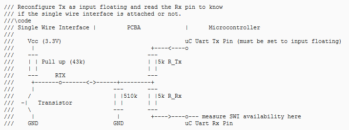
I have configured UART1_Rx and UART1_Tx as gpio INPUT floating (PULLUDDIS)
I am trying to read the values at UART1_Rx or UART1_Tx and they show me a HIGH signal.
Below, I've attached the Hardware wiring for the UART1_Rx and UART1_Tx
I would like to know why am I not able to get floating value as LOW ? Is there any influence of the Ball Reset Rel State on this ?
Also, if you could kindly provide me the internal schematics for the UART1_Tx and UART1_Rx, like how internally they're wired and what values of resistors used for pulling up or down.
Also, I am bit confused in understanding the Ball Reset Rel States mentioned in the datasheet.
– 0: The buffer drives VOL (pulldown or pullup resistor not activated)
0(PD): The buffer drives VOL with an active pulldown resistor
– 1: The buffer drives VOH (pulldown or pullup resistor not activated)
1(PU): The buffer drives VOH with an active pullup resistor
– Z: High-impedance.
– L: High-impedance with an active pulldown resistor
– H : High-impedance with an active pullup resistor
What exactly is the difference between 0 and L ; 1 and H ?
What would be the state of the UART1_Tx or Rx when configured as INPUT FLOATING (PULLUDDIS)
If you could guide me in better interpreting them, it would be a great help.

