This thread has been locked.

If you have a related question, please click the "Ask a related question" button in the top right corner. The newly created question will be automatically linked to this question.

RTOS/TDA2P-ACD: LCD - YUV output issue

Part Number: TDA2P-ACD

Tool/software: TI-RTOS

Hi,

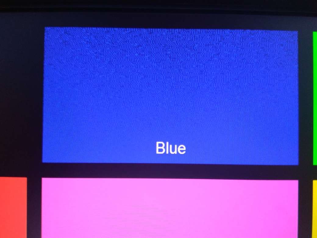
I'm trying to display YUV422 on LCD. Since, DSS does not support YUV422 output over discrete sync interface, refering to some posts on TI forum I found that the basic idea of how to get YUV422 is to "fool" DSS by saying that input YUV422 interleaved data is actually RGB565  and disable all pixel processing modules. I got YUV422 but the image is not 100% clear, it looks like it has  "snow noise"  on some colors.

DISPC_VID1_ATTRIBUTE (0x580010CC) register contains this value (0x8208880D)


Do you have some idea how to solve this?

Regards,

Nevena Stojanovic

  • Hi Nevena,

    Can you check if www.ti.com/.../sprac23a.pdf helps you.

    Regards,
    Rishabh
  • Hi Nevena,

    Looking at the image, it looks like some bits are getting inverted.
    What is your output interface size?
    Atleast, colors are correct, so DSS is configured correctly.

    Rgds,
    Brijesh
  • Hi.

    The "snow noise" issue was related to some HW problem.
    When I changed the board LCD3 works fine, but for LCD1 and LCD2 instances, colors are swapped (red/blue). When I enable two
    pipelines for LCD1 or LCD2, the colors are in the right order.

    I set DISPLAY_LINK_INST_DSS_VID2 for displayId in use-case:

    if(pPrm_VideoLCD)
    {
    pPrm_VideoLCD->rtParams.tarWidth = displayWidthLCD;
    pPrm_VideoLCD->rtParams.tarHeight = displayHeightLCD;
    pPrm_VideoLCD->displayId = DISPLAY_LINK_INST_DSS_VID2;
    }

    In chains_common.c I enabled only one video pipeLine:

    pVInfo->mode = 0;
    pVInfo->isInputPipeConnected[0] = FALSE;
    pVInfo->isInputPipeConnected[1] = TRUE;
    pVInfo->isInputPipeConnected[2] = FALSE;
    pVInfo->isInputPipeConnected[2] = FALSE;
    pVInfo->isInputPipeConnected[3] = FALSE;
    pVInfo->writeBackEnabledFlag = FALSE;

    pipeOvlyPrms[1].pipeLine = SYSTEM_DSS_DISPC_PIPE_VID2;
    pipeOvlyPrms[1].globalAlpha = 0xFF;
    pipeOvlyPrms[1].preMultiplyAlpha = 0;
    pipeOvlyPrms[1].zorderEnable = TRUE;
    pipeOvlyPrms[1].zorder = SYSTEM_DSS_DISPC_ZORDER0;

    status = System_linkControl(gChains_commonObj.displayCtrlLinkId,
    DISPLAYCTRL_LINK_CMD_SET_OVLY_PIPELINE_PARAMS,
    &gChains_commonObj.pipeParams[1],
    sizeof(DisplayCtrlLink_OvlyPipeParams),
    TRUE);

    With this changes LCD3 works fine, but for LCD1 and LCD2 I got swapped colors.

    VID2_ATTRIBUTES 0x5800115C = 0x4208880D
    DISPC_CONFIG2 0x58001620 = 0xC00
    DISPC_CONTROL2 0x58001238 = 0x129

    After writing the same value 0x4208880D in VID1_ATTRIBUTES or VID3_ATTRIBUTES registers, then I got colors in right order.

    Do you have any suggestions about this behavior?

    Regards.

    Nevena Stojanovic
  • Hi Nevena,

    In the fail case what is the value of VID1_ATTRIBUTES or VID3_ATTRIBUTES register?

    Regards,
    Rishabh
  • Hi Nevena,

    Could you please first understand the problem that you are facing?
    According to above LCD3 works fine, but LCD2 and LCD2 output does not.. But then you are saying, when two pipelines are enabled, color are right? How are there pipelines connected to LCD outputs ? Please note we cannot connect two pipelines to one LCD output..

    Also i see LCD2 output is eanbled for 16bit, is that correct?

    You will need to make sure the input format is RGB565 and output format set correctly as required for connected display..

    Rgds,
    Brijesh