This thread has been locked.

If you have a related question, please click the "Ask a related question" button in the top right corner. The newly created question will be automatically linked to this question.

RTOS/TDA2PXEVM: I want to pull up GPIO by vision SDK but fail

Part Number: TDA2PXEVM

Tool/software: TI-RTOS

hi all,

my board is dra76x, vision sdk is 0304 version.

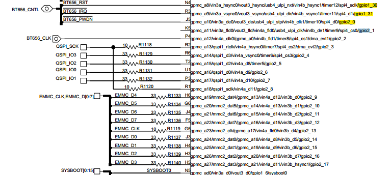
i want to pull up GPIO2 0 pin to high vol, so i add the following code in Bsp_boardPowerOnDeviceTda2xx() function of bsp_boardTda2xx.c file:

#define BOARD_GPIO_BASE_ADV7182_PWDN        ((UInt32) SOC_GPIO2_BASE)
#define BOARD_GPIO_PIN_ADV7182_PWDN         ((UInt32) 0U)

          GPIOModuleEnable(BOARD_GPIO_BASE_ADV7182_PWDN);

           // Set GIPO2_0 pin to high
            GPIODirModeSet(
                BOARD_GPIO_BASE_ADV7182_PWDN,
                BOARD_GPIO_PIN_ADV7182_PWDN,
                GPIO_DIR_OUTPUT);
            
            GT_1trace(BspBoardTrace, GT_INFO, "(1)GPIO2_0 PIN = %d!!\n",
                GPIOPinRead(BOARD_GPIO_BASE_ADV7182_PWDN, BOARD_GPIO_PIN_ADV7182_PWDN));    

            GPIOPinWrite(
                BOARD_GPIO_BASE_ADV7182_PWDN,
                BOARD_GPIO_PIN_ADV7182_PWDN,
                GPIO_PIN_HIGH);
            BspOsal_sleep((UInt32) 100U);  // wait 100ms

            GT_1trace(BspBoardTrace, GT_INFO, "(2)GPIO2_0 PIN = %d!!\n",
                GPIOPinRead(BOARD_GPIO_BASE_ADV7182_PWDN, BOARD_GPIO_PIN_ADV7182_PWDN));

before gpio write i read the gpio2_0 value, after GPIOPinWrite() be called, i read the gpio2_0 value, but both of them are 0,  gpio writing is not effect why?

could anyone please help me to figure out the problem? 

  • Hi,

    Is GPIO2 powered on? Can you read CM_L4PER_GPIO2_CLKCTRL register.

    Regards,
    Rishabh
  • hi,
    i use CCS debug tool to connect A15, I read the CM_L4PER_GPIO2_CLKCTRL register value is 0x00020001.
    best regards
  • Hi,

    It seems that GPIO2 is off. Can you refer to CSL example <pdk>\packages\ti\csl\example\gpio\gpio_interrupt\main.c.

    Regards,
    Rishabh
  • hi,
    thanks for your reply, i modify code according to example <pdk>\packages\ti\csl\example\gpio\gpio_interrupt\main.c as following:

    GT_1trace(BspBoardTrace, GT_INFO, "(1)CM_L4PER_GPIO2_CLKCTRL = 0x%x!!\n",
    HW_RD_REG32(SOC_L4PER_CM_CORE_BASE+CM_L4PER_GPIO2_CLKCTRL));
    /*Enable GPIO clock*/
    HW_WR_REG32(SOC_L4PER_CM_CORE_BASE+CM_L4PER_GPIO2_CLKCTRL, 0x102);

    while ((HW_RD_REG32(SOC_L4PER_CM_CORE_BASE+CM_L4PER_GPIO2_CLKCTRL) & (0x00030000U)) != 0x0) {
    BspOsal_sleep((UInt32) 10U); // wait 10 ms;
    }
    GT_1trace(BspBoardTrace, GT_INFO, "(2)CM_L4PER_GPIO2_CLKCTRL = 0x%x!!\n",
    HW_RD_REG32(SOC_L4PER_CM_CORE_BASE+CM_L4PER_GPIO2_CLKCTRL));


    GPIOModuleReset(BOARD_GPIO_BASE_ADV7182_PWDN);

    GPIOModuleEnable(BOARD_GPIO_BASE_ADV7182_PWDN);

    // Set GIPO2_0 pin to high
    GPIODirModeSet(
    BOARD_GPIO_BASE_ADV7182_PWDN,
    BOARD_GPIO_PIN_ADV7182_PWDN,
    GPIO_DIR_OUTPUT);

    GT_1trace(BspBoardTrace, GT_INFO, "(1)GPIO2_0 PIN = %d!!\n",
    GPIOPinRead(BOARD_GPIO_BASE_ADV7182_PWDN, BOARD_GPIO_PIN_ADV7182_PWDN));

    GPIOPinWrite(
    BOARD_GPIO_BASE_ADV7182_PWDN,
    BOARD_GPIO_PIN_ADV7182_PWDN,
    GPIO_PIN_HIGH);
    BspOsal_sleep((UInt32) 100U); // wait 100ms

    GT_1trace(BspBoardTrace, GT_INFO, "(2)GPIO2_0 PIN = %d!!\n",
    GPIOPinRead(BOARD_GPIO_BASE_ADV7182_PWDN, BOARD_GPIO_PIN_ADV7182_PWDN));

    the result is:

    [HOST] [IPU2 ] 733.836942 s: (1)CM_L4PER_GPIO2_CLKCTRL = 0x20001!!
    [HOST] [IPU2 ] 734.976880 s: (2)CM_L4PER_GPIO2_CLKCTRL = 0x101!!
    [HOST] [IPU2 ] 734.977215 s: (1)GPIO2_0 PIN = 0!!
    [HOST] [IPU2 ] 735.076892 s: (2)GPIO2_0 PIN = 0!!

    CM_L4PER_GPIO2_CLKCTRL is enable success, but the value of GPIO2 0 pin is also 0.
    best regards
  • Hi,

    Are you doing the pin mux?
    By mistake i pointed to wrong gpio example. You need to see <pdk>\packages\ti\csl\example\gpio\gpio_toggle\main.c.

    Regards,
    Rishabh
  • hi Rishabh,

    i refer the board design, gpio2 is pin mux as follow:

    best regards!

  • Hi,

    Are you configuring pins GPMC_A10 and GPMC_A11?
    Can you read registers 0x4A00_3468 and 0x4A00_346C and tell me the value.

    Regards,
    Rishabh
  • hi Rishabh,

    i use CCS debug tool to connect A15 core, then i pause A15 to check two registers' value sometime is:

    sometime i continue to run A15 and pause again to check the value is:

    beset regards

  • Hi,

    You need to set 0xE as MUXMODE for these pins to work as GPIO. You can refer to TRM for more details.

    Regards,
    Rishabh
  • hi Rishabh,
    thanks, now i add following code before pull up GPIO2 0 pin.
    Bsp_platformSetPinmuxRegs(
    (UInt32) CTRL_CORE_PAD_GPMC_A10_GPMC_A10_MUXMODE_GPIO2_0_14, // 14
    (UInt32) CTRL_CORE_PAD_GPMC_A10, // 0x68
    BSP_PLATFORM_IOPAD_CFG_DEFAULT); // 0xff

    then i check out the register value of 0x4A003468 by CCS tool, it also keep the value 0x00000040, not change.

    what's more,  i can not manual change this register value by CCS tool, for example if i set 0x4A003468 to 0x0E, after i press the Enter key, the value return to 0x00000040.
    i feel so confused.
    best regards

  • Hi,

    This means that this particular pin is being used by some other portion of SDK.
    Can you add a CCS watchpoint to see who is writing to this address.

    Regards,
    Rishabh
  • hi, Rishabh

    i sorry i feel confused, i read register value by "Memory browser" and Register is not same

  • Hi,

    Can you please set HW watchpoint in the beginning of the program for GPMC_10 pin and see who all are writing to this register.
    To understand watchpoint functionality refer to processors.wiki.ti.com/.../Watchpoint
    Please see PROCESSOR_SDK_VISION_03_06_00_00\vision_sdk\docs\TrainingSlides\CCS_Debug_Trace.pdf on how to set HW watchpoint.

    Regards,
    Rishabh

  • hi Rishabh,

    i add Hardware watchpoint by CCS like this:

    but it seem that it not work, no break happened, i am not load the firmware by CCS, i load the firmware of IPU2 from EMMC,  it is ok?  why breakpoint not be triggered?

    best regards!

  • Hi,

    Break point will be triggered when you run via CCS.
    Can you add the pin mux change just before configuring/accessing GPIO and see if the same is working.
    Also make sure that no other CPU is running in parallel. You can halt other CPUs using CCS.

    Regards,
    Rishabh
  • hi Rishabh,
    i can not do this, running pin mux change code on IPU2 core is triggered by app.out on A15 size. so i can not halt A15 core.
    now i can config the GPIO2 0 pin through system command on A15 size (andriod system running on A15) as following command:

    echo 32 > /sys/class/gpio/export
    echo out > /sys/class/gpio/gpio32/direction
    cat /sys/class/gpio/gpio32/direction
    echo 1 > /sys/class/gpio/gpio32/value
    cat /sys/class/gpio/gpio32/value // the value is 1

    can you give me investigation direction about this problem, why trough above commands to pull up GPIO2 0 pin is successful, but
    on M4 size failed.

    best regards!
  • Hi Fanok,

    You are running multiple binaries and some CPU is overwriting pin mux from GPIO to some other functionality.
    Did you try the above suggestion "Can you add the pin mux change just before configuring/accessing GPIO and see if the same is working."

    Regards,
    Rishabh
  • hi Rishabh,

    yes i had try, i add the pinmux change code just before pull up GPIO code like this sequence:

    Bsp_platformSetPinmuxRegs(
    (UInt32) CTRL_CORE_PAD_GPMC_A10_GPMC_A10_MUXMODE_GPIO2_0_14,
    (UInt32) CTRL_CORE_PAD_GPMC_A10,
    BSP_PLATFORM_IOPAD_CFG_DEFAULT);

    GPIOModuleReset(BOARD_GPIO_BASE_ADV7182_PWDN);
    GPIOModuleEnable(BOARD_GPIO_BASE_ADV7182_PWDN);

    GPIODirModeSet(
    BOARD_GPIO_BASE_ADV7182_PWDN,
    BOARD_GPIO_PIN_ADV7182_PWDN,
    GPIO_DIR_OUTPUT);

    GPIOPinWrite(
    BOARD_GPIO_BASE_ADV7182_PWDN,
    BOARD_GPIO_PIN_ADV7182_PWDN,
    GPIO_PIN_HIGH);

    but also not work.

    best regards!
  • Hi,

    Can you read the pin mux register to make sure the value is getting updated correctly before calling GPIOModuleReset.

    Regards,
    Rishabh
  • hi Rishabh,

    i read the mux pin value by add code, log as following:

    [HOST] [IPU2 ] 178.686451 s: (1)MuxAddr = 0x4a003468, MuxVal = 0xe // before set muxpin
    [HOST] [IPU2 ] 178.686543 s: (2)MuxAddr = 0x4a003468, MuxVal = 0xe // after set muxpin
    [HOST] [IPU2 ] 178.686665 s: (1)CM_L4PER_GPIO2_CLKCTRL = 0x20001!! // before set gpio2 clk
    [HOST] [IPU2 ] 181.226041 s: (2)CM_L4PER_GPIO2_CLKCTRL = 0x10101!! // after set gpio2 clk
    [HOST] [IPU2 ] 181.226163 s: Bsp_boardPowerOnDeviceTda2xx() Power ADV7182!!
    [HOST] [IPU2 ] 181.226255 s: (3)MuxAddr = 0x4a003468, MuxVal = 0xe // before GPIOModuleReset get the mux pin value
    [HOST] [IPU2 ] 181.226438 s: (1)GPIO2_0 PIN = 0!!   // before GPIOPinWrite
    [HOST] [IPU2 ] 181.326053 s: (2)GPIO2_0 PIN = 0!!   // after GPIOPinWrite

    you can see that the muxpin has already be set to value 0x0e (is gpio2 mode), so i think the problem is not muxpin is overwriting.
    best regards!

  • hi Rishabh,
    i feel sorry, after call GPIOPinWrite(), i use the multimeter to measure the voltage of the pin of the PWN pin of ADV7182, i found it is high level.
    i think gpio2 0 pin is pulled up success. i think call GPIOPinRead() function to read the value of GPIO pin with output direction might not be the real value of gpio?..
    best regards!
  • Hi,

    Can you share the GPIO register dump.

    Regards,
    Rishabh
  • Hi,

    I haven't heard back from you, I'm assuming you were able to resolve your issue.
    If not, just post a reply below (or create a new thread if the thread has locked due to time-out).

    Regards,
    Rishabh
  • hi Rishabh,
    i use voltmeter to measure the voltage of the pin which i want to pull up, it is switched from low to high level, i think it is successfull. i think i should not call GPIOPinRead() function to read the value of GPIO pin with output direction.
    best regards