This thread has been locked.

If you have a related question, please click the "Ask a related question" button in the top right corner. The newly created question will be automatically linked to this question.

TMS320C6746: Crystal not working after power on

Part Number: TMS320C6746


We are using TMS320C6746 DSP in multiple products.

We are getting issues in some boards with DSP running at 456MHz with core voltage 1.3V. Issue is related to, power-up and crystal/oscillator.


On working board, DSP (TMS320C6746EZWT3)  is running at 300MHz with core voltage 1.2V

Clock source is like this.


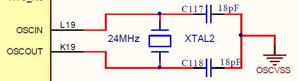
We never had any problem with this board.


Now, on a new board, DSP (TMS320C6746EZWT4) is expected to run at 456MHz with core voltage 1.3V

It doesn’t boot with every power on. It is random. Sometimes boots up, sometimes doesn’t.

Some boards never boot.

When it doesn’t boot, pressing reset button to processor makes the DSP boot and run.


Same board works fine when we parallel two 18pF caps on each leg. That means 36pF on each leg. Each power On, it boots fine.


We tried,

- single 36pF on each leg – doesn’t work

- single 33pf on each leg – doesn’t work

- 47pf on each leg – doesn’t work

- single 18pF on each leg – doesn’t work

- two 18pF on each leg - works fine


Placing a probe on one leg makes it boot fine.

If core voltage reduced to 1.2V, the board works fine at 456MHz also. But TI recommended core voltage is 1.3V for 456MHz for the part TMS320C6746EZWT4

It looks like core voltage is causing this issue.

TI recommends to use external Osc, as done in c6748 reference design.

Any suggestions.

  • Hi Bhaskar

    Feed back from one of our experts on this topic. 

    It is not obvious why a single 36pF capacitor doesn’t operate the same way as two 18pF capacitors connected in parallel.  Hopefully you are using ceramic NPO capacitors for this application.  NPO capacitors are readily available in these values and are stable across voltage and temperature with minimum aging effects.  High density multi-layer ceramic capacitors are not stable across voltage and temperature.


    Can you share the manufacture and part number information of crystal and capacitors being used for this testing?

    Additionally this may not help you if you have an existing board design, but in our device schematic checklist we recommend a resistor in series Rs.

    We have seen some issues like this from time to time with customers. Mostly system or crystal dependent.


    You can refer to 

    http://www.ti.com/lit/an/sprack9/sprack9.pdf


    section 2.3.4 on Rbias and Rs resistors


    Here is a similar sounding post that was fixed using series resistor

    >>TI recommends to use external Osc, as done in c6748 reference design.


    Yes I would strongly encourage to evaluate the errata

    http://www.ti.com/lit/er/sprz304h/sprz304h.pdf

    2.1.3


    Applications that require ESD immunity and have to be tested with  IEC 61000-4-2  test requirements - we see crystal susceptible to failures and strongly encourage use of an ext osc.

    Hope this helps.

    Regards

    Mukul 

  • Hi,
    Thank you for the response and support,
    Crystal P/N#: ABM3-24.000MHZ-D2Y-T (24MHz; 20ppm; ESR:30 Ohm) from Abracon
    Capacitor P/N#: GRM1885C1H330JA01D (33pF, 50V NPO) from Murata
    Series Resistor option is not yet tried

    Regards,
    Balaji A
  • Hi Balaji
    thanks for getting back. Looks like you are using ceramic caps.
    Is the series resistor experiment something you can try/planning to try?

    Regards
    Mukul
  • May I request you to recommend value of series resistor? Looking at the PCBA, It is difficult to fit series resistor. So we have plan to replace Crystal with Oscillator and test it once. Oscillator is more stable than Crystal.
  • It looks like Oscillator testing will take time, as quick temporary patch, we would like to reduce the core voltage to 1.2V and Processor speed to 375Mhz but the part [P/N#:TMS320C6746EZWT4] will remain same. Do you see any concern? currently 3/30 failed to boot ~10% failure rate. all 3 faulty boards works fine @ 1.2V. But the spec of 456MHz demands typ 1.3V, We would like to try 1.2V @ 375Mhz on TMS320C6746EZWT4. May I know your thoughts?
  • Hi Balaji,

    Setting CVDD to 1.2V seems like a valid workaround for operation upto 375MHz.

    The 1.2V operating point requires CVDD supply between 1.14V and 1.32V.
    And RVDD for 375 MHz also requires a supply between 1.14V and 1.32V.

    Let me ask about a recommended resistor value.

    Regards,
    Mark