Part Number: AM3359
Why was F22 and F21 swapped in Figure 7-18 on the datasheet which is changed from SPRS717J to SPRS717K?
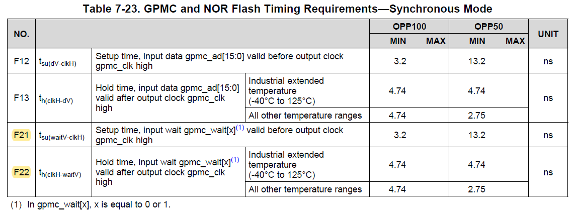
F21 and F22 are described in Table 7-23. They will not need to be swapped.
Best regards,
Daisuke
This thread has been locked.
If you have a related question, please click the "Ask a related question" button in the top right corner. The newly created question will be automatically linked to this question.
Part Number: AM3359
Why was F22 and F21 swapped in Figure 7-18 on the datasheet which is changed from SPRS717J to SPRS717K?
F21 and F22 are described in Table 7-23. They will not need to be swapped.
Best regards,
Daisuke
Hi Maeda-san,
Figure 7-18 was updated so F21 and F22 match Figure 7-21, but I have concerns about both figures in the SPRS717K version of the data manual.
I have found the LitBug where this change was requested and will follow up with the tech writer to understand the intent and correct these figures in the next data manual release. The AM437x DM should have also had this same change applied (incorrectly).
Figure 7-18. GPMC and NOR Flash—Synchronous Burst Read—4x16-Bit (GpmcFCLKDivider = 0)
F22 label is incorrectly used for setup time instead of hold time
F21 label is incorrectly used for hold time instead of setup time
Figure 7-21. GPMC and Multiplexed NOR Flash—Synchronous Burst Write
F22 label is correctly(?) used for hold time - hold time of WAIT inactive signal latched on a rise edge clock (before low going pulse) - seems incorrect to me.
F21 label is correctly(?) used for setup time - setup time of WAIT inactive signal latched on a rise edge clock (after low going pulse) - seems incorrect to me.
Thank you for bringing this issue to our attention.
Regards,
Mark
Hi Mark-san,
Thank you for your reply. Sorry for my late reply.
"The setup time F21 defines the time before CLK high transition that is required to indicate that data is valid. Similarly, the hold time F22 defines the time after CLK high transition that is required to indicate valid data."
I am still confused because these times seem to be not illustrated correctly in Figure 7-18 and Figure 7-21. I would appreciate to give an explanation to clear up the confusion here before the next revision is released.
Best regards,
Daisuke
Hi Maeda-san,
The easiest solution is to redraw the two figures where F21 and F22 are shown to appear like below.
These drawings simply show the setup time and hold time of the WAIT[x] signal as it is latched by the rising edge of GPMC_CLK.
We are coming up with a new figure that depicts when the WAIT[x] signal must be valid in order for the latching of data at the expected time (as defined by READACCESSTIME). I will share with you that figure once we have created it.
Does this help?
Regards,
Mark
Hi Mark-san,
Thank you for your reply. Sorry for my late reply.
Mark Mckeown said:
We are coming up with a new figure that depicts when the WAIT[x] signal must be valid in order for the latching of data at the expected time (as defined by READACCESSTIME). I will share with you that figure once we have created it.
I would appreciate it if you could give me the update here.
Best regards,
Daisuke