This thread has been locked.

If you have a related question, please click the "Ask a related question" button in the top right corner. The newly created question will be automatically linked to this question.

RTOS/TMDSIDK437X: GPIO delay between two GPIO outputs

Genius 5840 points
Part Number: TMDSIDK437X

Tool/software: TI-RTOS

Hello,

I measured two GPIO outputs executing following code(CPU frequency is 600MHz).

GPIO_write(7, GPIO_PIN_VAL_HIGH);
GPIO_write(8, GPIO_PIN_VAL_HIGH);

Measurement result is as below.

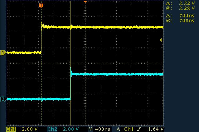
I think the delay time is seemed to be too long between two GPIO outputs.

What are the possible causes?

Is it overhead of GPIO driver ?

I also attached CCS Project.

CCSProject.zip 

Regards,

U-SK

  • U-SK,

    Please refer to GPIO toggle experiment that is provided in the document below:

    http://www.ti.com/lit/ug/tidu461/tidu461.pdf

    Screenshot for easy reference:

    The PRU is likely better at toggling a simple GPIO than ARM core.

    Having said that the number reported are a little on the high side so it could be possible that your build options or the driver code is adding to the absolute best numbers that can be obtained from the ARM.  To reduce this the GPIO toggle can be done using lower level register write or using functional CSL API. To do this directly from the register you can use GPIO_DATAOUT or  (GPIO_CLRDATAOUT/GPIO_SETDATAOUT ) as described in code above.

    The GPIO_write API from the GPIO LLD driver uses indexing so the value passed from the API converts index to port number and pin number and also seems to have interaction to check state of interrupts. YOu can locate the source for the API at GPIO_v1.c in the folder 

    pdk_am437x_1_0_10\packages\ti\drv\gpio\src\v1

    Hope this helps.

    Regards,

    Rahul

  • Hi Rahul,

    Thank you for your reply.

    I added following function and measured gpio toggle time.

    BitToggle(SOC_GPIO0_REG + GPIO_SETDATAOUT,SOC_GPIO0_REG + GPIO_CLEARDATAOUT);

    The contents of the function are as follows:

    unsigned long BitToggle(unsigned long val1, unsigned long val2){
       asm(
          " mov r2, #0x00004000" "\n\t"
          "str r2,[r0]" "\n\t"
          "str r2,[r1]" "\n\t"
       );
       return val1;
    }

    The measured result is as below.(TMDSIDK437x is running at 600MHz)

    I think it seems to be long compered to your bench data.

    What kind of device is used for the following data?

    How many operating frequencies does the device run?

    Regards,

    U-SK

  • AM335x at 600Mhz was used for the screen shot that we provided. What memory are you running the code from DDR Or OCRAM ? Have you setup the MMU and cache for A9 core ?  What is the target GPIO toggle time for this exercise. Cortex A class device is unlikely to meet the MCU latency for toggling a GPIO.

    Regards,

    Rahul 

  • Hi Rahul,

    Thank you for your reply.

    The program should be executed from DDR.

    I'm using rtos_template_app_am437x_a9 project and didn't changed MMU and cache setting.

    The project I measured GPIO toggle is as below.

    SampleProject.zip 

    I would like to minimize GPIO delay time as short as possible.

    And available PRU is nothing because it will be used for Industrial Ethernet and motor feedback.

    Can I reduce GPIO delay time from my measurement data without PRU in AM437x(CPU frequency can't be raised )?

    Regards,

    U-SK

  • Hi Rahul,

    Do you have any updates about my question?

    Regards,
    U-SK
  • U-SK,

    the RTOS template app should have the right MMU setup for toggling GPIO. AM437x CPU speed can be increased to 1GHz in Nitro mode. Please use the following AM437x spreedsheet to change the MPU PLL.

    6835.AM43xx_DPLL_Settings.xlsx

    Please note that core voltage provided by PMIC needs to be changed to set MPU in NItro mode.

    Regards,

    Rahul