This thread has been locked.

If you have a related question, please click the "Ask a related question" button in the top right corner. The newly created question will be automatically linked to this question.

AM6526: Creating an interrupt from PRU to R5F

Part Number: AM6548

Do we have an example of how to generate an interrupt for one of the R5F cores coming from ICSSG2/PRU0 (PRU->R5F). Source code snippets for configuration and triggering would also be helpful. We'd like to use one of the PRU registers as the source for the interrupt.

Thanks,
Eddie

  • Eddie,

    We don't have a standalone build-box type PRU/R5F interrupt setup example, but the emac driver and icssg firmware in Processor SDK RTOS includes the necessary configuration that customers can refer to:

    R5F driver: pdk_am65xx_1_0_3\packages\ti\drv\emac\src\v5
    PRU firmware: pdk_am65xx_1_0_3\packages\ti\drv\emac\firmware\icss_eth\src

    Regards,
    Garrett
  • [Edited]

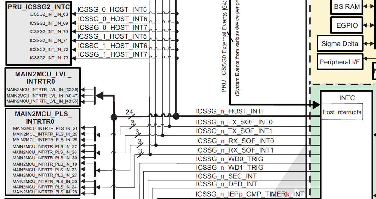
    Unlike PRU-ICSSM host interrupt directly connecting to ARM interrupt controller in AM335x or through crossbar in AM57x, the PRU-ICSSG host interrupts are routed to MCU R5F through level or pulse interrupt routers, see TRM Figure 9-1. SoC Interrupt Architecture 

    and Figure 6-110. PRU_ICSSG Integration:

    The interrupt router thus need to be configured via CSL function as below:

      CSL_IntrRouterCfg intrRouterCfg;

       uint32_t           pruIntRtrInIntNum,pruIntRtrOutIntNum;


      /* Initialize Main to MCU Interrupt Router config structure */

       intrRouterCfg.pIntrRouterRegs = (CSL_intr_router_cfgRegs *)(uintptr_t)(CSL_MAIN2MCU_LVL_INTRTR0_CFG_BASE);

       intrRouterCfg.pIntdRegs       = (CSL_intr_router_intd_cfgRegs *)(uintptr_t)NULL;

       intrRouterCfg.numInputIntrs   = 192;

       intrRouterCfg.numOutputIntrs = 64;


       /* Route PRU int router output to MAIN2MCU int router output, MAIN2MCU int router output int number

         * is derived from the MCU GIC interrupt number.*/

        /* 32: ICSSG_0_HOST_INT0 PRU_ICSSG0 host interrupt 2, see TRM 9.4.10 MAIN2MCU_LVL_INTRTR0 Interrupt Map */

       pruIntRtrInIntNum = 32;

       pruIntRtrOutIntNum = CSL_GIC0_INTR_PRU_ICSSG0_BUS_PR1_HOST_INTR_PEND_0 - CSL_MCU0_INTR_MAIN2MCU_LVL_INTR0_OUTL_0; //286 -160, see cslr_intr_gic0.h and cslr_intr_mcu0.h

       CSL_intrRouterCfgMux(&intrRouterCfg, pruIntRtrInIntNum, pruIntRtrOutIntNum);


    And registering the interrupt in R5F via Osal functions:

          HwiP_Handle hwiHandle = NULL;

         OsalRegisterIntrParams_t interruptRegParams;

                  /* Initialize with defaults */

                   Osal_RegisterInterrupt_initParams(&interruptRegParams);

                    interruptRegParams.corepacConfig.isrRoutine = (&pru_hwiFxn);

                    interruptRegParams.corepacConfig.priority = 0x20U;

                   interruptRegParams.corepacConfig.name=NULL;

                   interruptRegParams.corepacConfig.corepacEventNum=CSL_MCU0_INTR_MAIN2MCU_LVL_INTR0_OUTL_0;

                   interruptRegParams.corepacConfig.intVecNum=CSL_MCU0_INTR_MAIN2MCU_LVL_INTR0_OUTL_0; /* Host Interrupt vector */

                    /* Register interrupts */

                   OsalRegisterInterrupt(&interruptRegParams,&(hwiHandle));

    Note: as mentioned in previous post, there is no existing standalone R5F/PRU interrupt example code in PRSDK. Above code is based on other examples for reference only.

    Regards,

    Garrett

  • Part Number: AM6548

    Hi,

    I try to interact between ARM Core R5F and the PRU. I would like to send a "Interrupt" from R5F to the PRU.

    My problem is, I don't know/understand how to generate a specific System Event with the R5F. I've searched the CSL package, read the TRM of AM6548 and the amount of information overwhelm me a bit.

    I think my first problem is, that I don't know the exactly definition of the term "Interrupt" and "System Event". What is the difference of both?
    Second problem: Do I need to enable the OCP-Port of ICSSG to send Interrupts between the ARM and the PRUs?

    Figure 6-111. PRU_ICSSG Integration shows me, that PRU_ICSSG0_External Events [64..159] are "System Events from various device peripherals). Can I generate such a System Event with the R5F?

    I've configured the INTC of PRU_ICSSG in such a way, that SysEvent 0 is mapped to Channel 0, and Channel 0 is mapped to Host 0. I've also enabled interrupts for Host 0 on ICSSG. So I "just" need to generate somehow the SysEvent 0....

    Thanks a lot in advance!

    Thomas

  • Thomas,

    Since your question appears to be similar to what Eddie posted here, I have merged the thread. Please look at the guidance provided by Garrett here on how to configure the R5F interrupts.

    Regards,
    Rahul
  • Thomas,

    TRM section 9.4.5 PRU_ICSSG0 Interrupt Map lists all the mapping of events [64:159] to the PRU_ICSSG0 external interrupt inputs. And 9.4.3 MCU_R5_CORE0 Interrupt Map lists the mapping of events to the MCU_R5_CORE0. Which PRU_ICSSG0_External Event do you try to generate from R5F? Note the PRU_ICSSG Interrupt Controller (INTC):

    – Up to 64 internal events, generated by modules, internal to the PRU_ICSSG

    – Up to 96 external events, generated by the system

    Also regarding to the host and channel, please refer to 6.4.6.1 PRU_ICSSG Interrupt Controller Functional Description

    • Host Interrupt 0 is connected to bit 30 in register 31 (R31) of PRU0 and PRU1 in parallel.
    • Host Interrupt 1 is connected to bit 31 in register 31 (R31) for PRU0 and PRU1 in parallel.
    • Host Interrupts 2 through 9 exported from PRU_ICSSG and mapped to device level interrupt controllers.

    "Most of the system events are routed directly to the various proccesing elements but in some cases it is impractical to route all events of a certain group (for example, GPIO events) to each processing element. For this purpose, the SoC integrates several Interrupt Router (INTRTR) instances. Each Interrupt Router

    aggregates a number of system events and can route each event to a given processing element by using simple combinational logic (a set of multiplexors). Event selection is controlled through the associated registers within each Interrupt Router.", so you don't have to enable OCP-port for sending interrupts between ARM and PRU.

    Regards,
    Garrett

  • Thomas,

    Please note I edited previous post on interruptRegParams.corepacConfig.corepacEventNum. Only in C66X the interrupt needs to be grouped to {0,1,2,3} to either of the four 32-bit event registers, and on AM654x, it should be equal to intVecNum.

    Regards,
    Garrett
  • Thank you very much for jumping in Garret. I didn't receive any email notification that my thread was merged, I just noticed it now. I will have a look at it now and come back with the result.

    Regards,
    Thomas
  • Hi Garrett,

    to your question "Which PRU_ICSSG0_External Event do you try to generate from R5F?"
    I have no particular event in mind, I just wanted to send a system event to the PRU which was generated by software from the R5F.

    However, meanwhile I found the function "PRUICSS_pruSendEvent(pruHandle, ARM_PRU0_EVENT);" which does the job for me. Thanks again Garrett for your explanation.

    But back to the origin of this thread: Creating an interrupt from PRU to R5F.

    I struggle a bit to create a system from PRU0 of ICSSG0 and send it to first R5F.

    This is how I understand the interrupt chain from PRU0 to R5F works: Can you check if I miss something there?

    1. Generating INTC System Event from Pru0

    Writing 0x20 to R31 will generate PRU_ICSSG0 internal Interrupt 16. I assume this is also known as Host Interrupt 2 of PRU_ICSSG, when reading Chapter 6.4.7.1 PRU_ICSSG Interrupt Controller Functional Description, but I am not sure.

    Host-2 of PRU_ICSSG0 is connected to MAIN2MCU_LVL_INTRTR0.

    Therefore, for the configuration of the MAIN2MCU_LVL_INTRTR0 router, the input interrupt number is 32 as you stated in your example.


    The interrupt number 162 of MCU_R5_CORE0 is the host interrupt 2 from the ICSSG0? So I have to configure MAIN2MCU_LVL_INTRTR0 in such a way that input interrupt number is 32 and the output interrupt number is 162?

    Is my path/chain correct up to here?

    I do not understand your example code at this line:
    pruIntRtrOutIntNum = CSL_GIC0_INTR_PRU_ICSSG0_BUS_PR1_HOST_INTR_PEND_0 - CSL_MCU0_INTR_MAIN2MCU_LVL_INTR0_OUTL_0; //286 -160, see cslr_intr_gic0.h and cslr_intr_mcu0.h

    Why subtract 160 from 286?

    I hope you could give me some hints
    Best regards,
    Thomas

  • Thomas,

    The path/chain you described is correct. Some clarification:

    1.
    >>Writing 0x20 to R31 will generate PRU_ICSSG0 internal Interrupt 16. I assume this is also known as Host Interrupt 2 of PRU_ICSSG, when >>reading Chapter 6.4.7.1 PRU_ICSSG Interrupt Controller Functional Description, but I am not sure.

    Please refer to section 6.4.7.2 PRU_ICSSG Interrupt Controller Basic Programming Model, to map the event 16 to host interrupt 2.
    2). Map event to INTC channel through ICSSG_CH_MAP_REGi (where i=0 to 39) channel mapping registers.
    3). Map channel to host interrupt through ICSSG_HINT_MAP_REG0 to ICSSG_HINT_MAP_REG4 registers.

    2. >>Why subtract 160 from 286?
    Actually it should be 162 as you indicated. CSL_intrRouterCfgMux() takes MCU R5 interrupt number (as shown main_led_blink.c at inpdk_am65xx_1_0_3\packages\ti\drv\gpio\test\led_blink\src) instead of the one from GIC0. I incidentally looked into another example code for a device with a 'MCU GIC'.

    Regards,
    Garrett
  • Hi Garrett,

    thank you for clarification!

    Nevertheless the isrRoutine getting not executed, when I generate Host Interrupt 2 of PRU_ICSSG0. I still search the cause for this.

    Just to clear point 2:
    Should I subtract 162 from 286, or just use the value 162 for outputIntrNum of CSL_intrRouterCfgMux?

    This is from my code now:

        int pruIntRtrInIntNum = 32;
        int pruIntRtrOutIntNum = /*CSL_GIC0_INTR_PRU_ICSSG0_BUS_PR1_HOST_INTR_PEND_0 -*/ CSL_MCU0_INTR_MAIN2MCU_LVL_INTR0_OUTL_2; 
        CSL_intrRouterCfgMux(&intrRouterMain2MCUCfg, pruIntRtrInIntNum, pruIntRtrOutIntNum);

  • I could solve the problem:

    I wasn't aware, that MAIN2MCU_RTR_LVL_MUX_INTR 0 is connected to MCU_R5_CORE0_INT_IN 160.
    Therefore its required to subtract 160 from CSL_MCU0_INTR_MAIN2MCU_LVL_INTR0_OUTL_2.

    The ISR is now going executed on the R5! Thanks for your patience and hints Garrett!

    Regards,
    Thomas

  • Hi Thomas,

    Thanks for your update, glad to know you are able to get this working! The thread should help a lot for other customers as well.

    The description of MAIN2MCU_LVL_INTRTR0_MUXCNTL_y register doesn't seem to be quite clear on the input and output interrupt numbers. If looking into the implementation of CSL_intrRouterCfgMux():

         /* Configure mux value */

           CSL_FINS( regVal, INTR_ROUTER_CFG_MUXCNTL_ENABLE, inputIntrNum );

           CSL_REG32_WR( &pCfg->pIntrRouterRegs->MUXCNTL[outputIntrNum], regVal );

    It makes sense to subtract 160 from CSL_MCU0_INTR_MAIN2MCU_LVL_INTR0_OUTL_2 with the configuration:

      intrRouterCfg.numInputIntrs   = 192;

      intrRouterCfg.numOutputIntrs = 64;

    Regards,

    Garrett