This thread has been locked.

If you have a related question, please click the "Ask a related question" button in the top right corner. The newly created question will be automatically linked to this question.

CCS/AM5728: PWM generation

Part Number: AM5728

Tool/software: Code Composer Studio

Hi, 

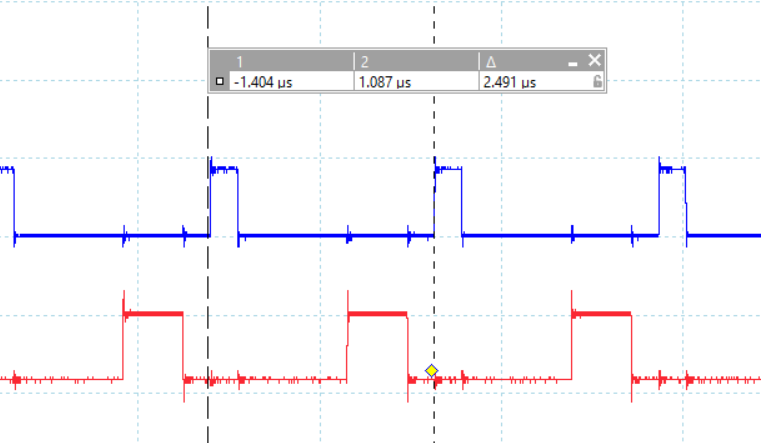
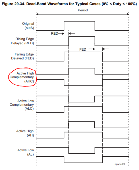
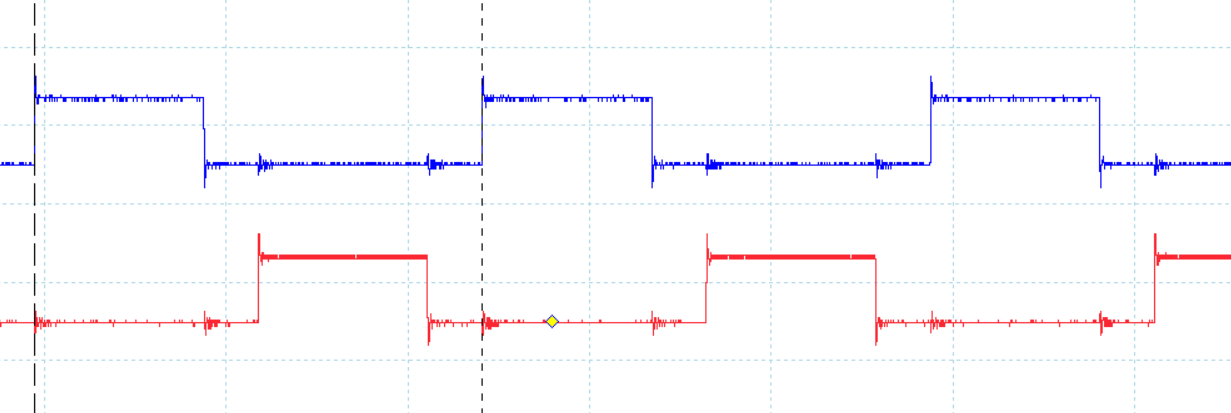
Am trying to generate dc-ac sine wave signal using CSL- ePWM library with deadband feature. But i confuse with what configuration of register is required to generate below required pulse using two channels of PWM

Am able to generate pulses as per required duty cycle but not exactly what is looking in shared image. 

Is there any good document for that TRM i already refer. But something am missing to achieve required result.

Thanks 

Akash

  • Akash,

    Is the image you posted what you are trying to achieve, or what you are currently seeing on the scope with your settings?

    Can you post the settings that you are currently trying?

    You should be able to use the A and B signals of one ePWM to generate the complementary pair that I think you are trying to achieve. The ePWM peripheral should be able to take a duty cycle for the A signal and then use that and the deadband information to create the complementary B signal for you.

    The TRM is our best source of information for the PWMs and has a few 'Waveforms for Common ePWM Configurations'. Figure 29-30 in section 29.2.2.5.4 of the TRM (www.ti.com/.../spruhz6) should be very close to what you are looking for. In this configuration you have two options:
    1) Create CMPA and CMPB values manually that will add the deadband you desire between the complementary signals
    2) Use the Deadband module to create the EPWMxB signal for you based on the CMPA value and the RED and FED values

    Jason Reeder

  • HI Jason,

    Below are my configuration settings am using to generate complementary PWM signals using Deadband feature. Also found my current waveform.

    My doubt in this:

    1. not able to get information whether i need to feed counter compare value for both PWM channels or i need to reuse value for PWMA for PWMB

    2. Want to sync both channels A & B as per duty cycle 

    ./**
    * \brief Output channel - A or B.
    *
    * Note: If changed to channel B, pinmux changes needs to be taken care
    * in the application.
    */
    #define APP_EHRPWM_OUTPUT_CH (CSL_EPWM_OUTPUT_CH_A)

    /** \brief Frequency of PWM output signal in Hz - 400 KHz is selected */
    #define APP_EHRPWM_OUT_FREQ (400U * 1000U)

    /** \brief Duty Cycle of PWM output signal in % - give value from 0 to 100 */
    #define APP_EHRPWM_DUTY_CYCLE (25U)

    #if 0
    /** \brief APP run time in seconds */
    #define APP_RUN_TIME (10U)

    /** \brief APP run count in event equal zero ISR count */
    #define APP_RUN_TIME_ISRCOUNT (APP_RUN_TIME * APP_EHRPWM_OUT_FREQ)
    #endif

    /**
    * \brief Functional clock to the PWMSS.
    * Fixed for the platform - can't be changed.
    */
    #define SOC_EHRPWM_MODULE_FREQ (133U * 1000U * 1000U)

    /** \brief TB frequency in Hz - so that /4 divider is used */
    #define APP_EHRPWM_TB_FREQ (SOC_EHRPWM_MODULE_FREQ / 4U)

    /**
    * \brief PRD value - this determines the period
    *
    * PRD = (TBCLK/PWM FREQ) / 2
    * NOTE: /2 is added becasue up&down counter is selected. So period is 2 times
    */
    #define APP_EHRPWM_PRD_VAL ((APP_EHRPWM_TB_FREQ \
    / APP_EHRPWM_OUT_FREQ) / 2U)
    /**
    * \brief COMPA value - this determines the duty cycle
    *
    * COMPA = (PRD - ((dutycycle * PRD) / 100)
    */
    #define APP_EHRPWM_COMPA_VAL (APP_EHRPWM_PRD_VAL - \
    ((APP_EHRPWM_DUTY_CYCLE * \
    APP_EHRPWM_PRD_VAL) / 100U))


    /** \brief IP default configuration */
    static CSL_EpwmAppPwmObj_t gAppPwmObj =
    {
    APP_EHRPWM_OUTPUT_CH, /* pwmCh */
    APP_EHRPWM_INST_BASE_ADDR, /* instAddr */
    SOC_EHRPWM_MODULE_FREQ, /* funcClk */
    TRUE, /* enableDeadband */
    FALSE, /* enableChopper */
    FALSE, /* enableTripzone */
    FALSE, /* enableEventTrigger */
    FALSE, /* enableHighResolution */
    /* CSL_EpwmAppPwmCfg_t*/
    {
    /* CSL_EpwmTimebaseCfg_t */
    {
    APP_EHRPWM_TB_FREQ, /* tbClk */
    APP_EHRPWM_OUT_FREQ, /* pwmtbCounterFreqPrd */
    CSL_EPWM_TB_COUNTER_DIR_UP_DOWN, /* tbCntrDirection */
    FALSE, /* enableSynchronization */ /* Change from FALSE */
    PWMSS_EPWM_TBCTL_PHSDIR_COUNT_DOWN, /* cntDirAfterSync */
    0U, /* phsCountAfterSync */
    PWMSS_EPWM_TBCTL_SYNCOSEL_EPWMXSYNC /* syncOutSrc */
    },
    /* CSL_EpwmCounterCmpCfg_t */
    {
    APP_EHRPWM_COMPA_VAL, /* cmpAValue */
    APP_EHRPWM_COMPA_VAL /* cmpBValue */
    },
    /* CSL_EpwmAqActionCfg_t */
    {
    CSL_EPWM_AQ_ACTION_DONOTHING, /* zeroAction */
    CSL_EPWM_AQ_ACTION_DONOTHING, /* prdAction */
    CSL_EPWM_AQ_ACTION_HIGH, /* cmpAUpAction */
    CSL_EPWM_AQ_ACTION_LOW, /* cmpADownAction */
    CSL_EPWM_AQ_ACTION_HIGH, /* cmpBUpAction */
    CSL_EPWM_AQ_ACTION_LOW /* cmpBDownAction */
    },
    /* CSL_EpwmDeadbandCfg_t */
    {
    CSL_EPWM_DB_IN_MODE_A_RED_A_FED, /* inputMode */
    CSL_EPWM_DB_OUT_MODE_A_RED_B_FED, /* outputMode */
    CSL_EPWM_DB_POL_SEL_ACTV_HIGH_COMPLEMENTARY, /* polaritySelect */
    10U, /* risingEdgeDelay */
    40U /* fallingEdgeDelay */
    },
    /* CSL_EpwmChopperCfg_t */
    {
    CSL_EPWM_CHP_DUTY_CYCLE_PERC_12PNT5, /* dutyCycle */
    CSL_EPWM_CHP_CLK_FREQ_DIV_BY_1, /* clkFrequency */
    CSL_EPWM_CHP_OSHT_WIDTH_1XSYSOUT_BY_8 /* oneShotPulseWidth */
    },
    /* CSL_EpwmTripzoneCfg_t */
    {
    CSL_EPWM_TZ_TRIP_ACTION_DO_NOTHING, /* tripAction */
    CSL_EPWM_TZ_EVENT_ONE_SHOT, /* tripEvtType */
    0U, /* tripPin */
    FALSE /* enableTripIntr */
    },
    /* CSL_EpwmEtCfg_t */
    {
    CSL_EPWM_ET_INTR_EVT_CNT_EQ_ZRO, /* intrEvtSource */
    /* CSL_EPWM_ET_INTR_PERIOD_FIRST_EVT */ /* intrPrd */
    CSL_EPWM_ET_INTR_PERIOD_DIS_INTR /* Disable Interrupt */
    }
    }
    };

    Below is Required Pulse: Both channels are properly sync that am not able to achieve in mine case. 

    Also not able to get how to calculate value for CompA & CompB, Right now am using same value for both with formula mention above. 

    Thanks

    Akash

  • Akash,

    From your settings, you have chosen that EPWMxA (from the action-qualifier) is the source for both the falling-edge and rising-edge delay ( CSL_EPWM_DB_IN_MODE_A_RED_A_FED).

    You are using Active High Complementary polarity (CSL_EPWM_DB_POL_SEL_ACTV_HIGH_COMPLEMENTARY)

    You have also chosen that dead-band should be fully enabled for both rising edge on EPWMxA and falling edge on EPWMxB (CSL_EPWM_DB_OUT_MODE_A_RED_B_FED)

    This means that your output signals will only be based on the CMPA value (EPWMxB will be created based on CMPA and the RED/FED values) and it will match the Active High Complementary example from Figure 29-34 in the TRM:

    I have taken your scope capture and marked it up in the same way as the TRM diagram to show you:

    You can see what your original signal would like like without deadband at the top, and then I've marked the RED delay (10) and the FED delay (40).

    Your FED delay being so large is actually making your complementary signal spill over into the next period.

    A different option to achieve your goal would be to not use the deadband module, and instead program a complementary value for the CMPB event that would create the EPWMxB signal.

    Jason Reeder

  • Hi Jason, 

    Is there any standard formula to feed value in CMPA & CMPB as my signals need to proper synched in terms of dutycycle. For example in below image On/Off duration of both pulse is same

  • Akash,

    Do you need complementary PWM signals that are meant to never be active at the same time? Or do you need two PWM signals that will always have the same duty cycle but be phase-shifted from one another?

    Your 25% duty cycle example seems to be a special case where it satisfies both methods, but what do you want your waveform to look like at 50% duty cycle, or 75% duty cycle? Your answer to this question will make the solution easier to suggest.

    Jason Reeder
  • Hi Jason,
    I need Complementary PWM signals that have never been active at the same time to operate MOSFETS in H-Bridge to generate a sinusoidal waveform
  • Please show me what you would like a 50% and 75% duty cycle signal to look like. The only example you've given is an ideal case where both A and B signals are 25% of the duty cycle and are perfectly phase offset from one another.

    I've explained how the deadband generator works and I've even overlayed your RED and FED values on top of your scope capture image so you can compare what the TRM says and how it is manifesting itself in your scope capture. This knowledge should allow you to adjust the RED and FED values to create your A and B signals based on your use case.

    The alternative for you would be to bypass the deadband generator completely and provide duty cycle values for both A and B signals. Figure 29-29 in the TRM and Table 29-36 in the TRM provide an example for this. The only difference for you is that you would want the B signal to be active high (that is, the high time duty cycle is proportional to CMPB) instead of active low as shown in the figure.

    Jason Reeder
  • Hi Jason,
    If I tried with phase shift module then how to achieve a phase shift of 180 degrees between two pulses & also am using PWM3 to generate these pulses. So is there any need of PWM1 & PWM2 for synchronization.
    Akash Garg
  • Hi Jason,

    Am able to generate DB but there is some uncertainty regarding configuration, kindly see current configuration am using to generate DB shown in image : But having certain doubts regarding value used for:

    1. SOC_EHRPWM_MODULE_FREQ ( why it's taken as 133 in CSL example )

    2. TB frequency in Hz - so that /4 divider is used

    3. PRD calculation

    4. COMPA & COMPB value

    5. TRM mentions about RED /FED  calculation. But if used RED & FED in DB config, am not able to achieve pulse.

    Below are the configuration am using right now

    /* Frequency of PWM output signal in Hz - 100 KHz is selected */

    #define APP_EHRPWM_OUT_FREQ             (100U * 1000U)

    /* Functional clock to the PWMSS. */

    #define SOC_EHRPWM_MODULE_FREQ          (133U * 1000U * 1000U)

    /* TB frequency in Hz - so that /4 divider is used */

    #define APP_EHRPWM_TB_FREQ              (SOC_EHRPWM_MODULE_FREQ / 4U)

    /**

    *  \brief PRD value - this determines the period

    *

    *  PRD = (TBCLK/PWM FREQ) / 2

    *  NOTE: /2 is added because up&down counter is selected. So the period is 2 times

    */

    #define APP_EHRPWM_PRD_VAL              ((APP_EHRPWM_TB_FREQ  \

                                             / APP_EHRPWM_OUT_FREQ) / 2U)

    /**

    *  \brief COMPA value - this determines the duty cycle

    *

    *  COMPA = (PRD - ((dutycycle * PRD) / 100)

    */

    #define APP_EHRPWM_COMPA_VAL            (APP_EHRPWM_PRD_VAL -                  \

                                               ((APP_EHRPWM_DUTY_CYCLE *          \

                                                   APP_EHRPWM_PRD_VAL) / 100U))

    #define APP_EHRPWM_COMPB_VAL            (APP_EHRPWM_COMPA_VAL / 8)

    #define DBRED 10U

    #define DBFED 10U

    #define RED ( DBRED *  APP_EHRPWM_PRD_VAL )

    #define FED ( DBFED *  APP_EHRPWM_PRD_VAL )

    ///////////////////////////////////////////////////////////////////////

    /** \brief IP default configuration */

       APP_EHRPWM_OUTPUT_CH,                       /* pwmCh */

       APP_EHRPWM_INST_BASE_ADDR,            /* instAddr */

       SOC_EHRPWM_MODULE_FREQ,                 /* funcClk */

       TRUE,                                                                      /* enableDeadband */

       FALSE,                                                                    /* enableChopper */

       FALSE,                                                                   /* enableTripzone */

       FALSE,                                                                   /* enableEventTrigger */

       TRUE,                                                                    /* enableHighResolution */

    /* CSL_EpwmAppPwmCfg_t*/

           /* CSL_EpwmTimebaseCfg_t */

           {

               APP_EHRPWM_TB_FREQ,                    /* tbClk */

               APP_EHRPWM_OUT_FREQ,                /* pwmtbCounterFreqPrd */

               CSL_EPWM_TB_COUNTER_DIR_UP_DOWN,      /* tbCntrDirection */

               FALSE,                                                                                  /* enableSynchronization */  

               CSL_EPWM_TB_CNT_DIR_AFT_SYNC_DOWN,  /* cntDirAfterSync */

               0U,                                                                                        /* phsCountAfterSync */

               CSL_EPWM_TB_SYNC_OUT_EVT_DISABLE        /* syncOutSrc */

           },

           /* CSL_EpwmCounterCmpCfg_t */

           {

               APP_EHRPWM_COMPA_VAL,               /* cmpAValue */

               APP_EHRPWM_COMPB_VAL                /* cmpBValue */

           },

           /* CSL_EpwmAqActionCfg_t */

           {

               CSL_EPWM_AQ_ACTION_DONOTHING,       /* zeroAction */

               CSL_EPWM_AQ_ACTION_DONOTHING,       /* prdAction */

               CSL_EPWM_AQ_ACTION_HIGH,            /* cmpAUpAction */

               CSL_EPWM_AQ_ACTION_LOW,             /* cmpADownAction */

               CSL_EPWM_AQ_ACTION_HIGH,            /* cmpBUpAction */

               CSL_EPWM_AQ_ACTION_LOW              /* cmpBDownAction */

           },

           /* CSL_EpwmDeadbandCfg_t */

           {

               CSL_EPWM_DB_IN_MODE_A_RED_A_FED,                                      /* inputMode */

               CSL_EPWM_DB_OUT_MODE_A_RED_B_FED,                                /* outputMode */

               CSL_EPWM_DB_POL_SEL_ACTV_HIGH_COMPLEMENTARY,   /* polaritySelect */

               DBRED,                                       /* risingEdgeDelay */

               DBFED                                        /* fallingEdgeDelay */

           },

    Result pulse generated using above settings:

    Also i need to use COMPB value during counter compare configuration to generate above pulse. So am little bit confused regarding configuration. My aim is to generate complementary  pulse using DB between 0 to 50% duty cycle.

    Thanks 

    Akash 


  • Hi Jason,

    Am able to control required PWM signal's A & B using dead-band feature with respect to frequency and duty-cycle. Just want to add 180 degree phase shift between them, but unable to do that. Can i know how to apply phase shift of 180 degree between two pulse.

    Thanks 

    Akash 

  • Akash,

    Sorry for the delay, I have been away from my desk.

    Please confirm if my understanding is correct:
    * duty cycle (signal A) will always be between 0-50% (never greater than 50%)
    * complementary signal (signal B) should have the exact same duty cycle but be phase shifted by 180 degrees

    If this is what you want, then the dead-band feature of the ePWM module cannot create this as this is not typically what dead-band refers to.

    Try the following (assuming the bullet points above are what you want):
    Disable the dead-band feature and manually calculate/program the CMPA and CMPB values of one ePWM module to produce what you want (below assumes up-down count mode):
    CMPA = period - (duty_cycle / 2)
    CMPB = duty_cycle / 2

    Jason Reeder