This thread has been locked.

If you have a related question, please click the "Ask a related question" button in the top right corner. The newly created question will be automatically linked to this question.

66AK2G12: 66AK2G12

Part Number: 66AK2G12

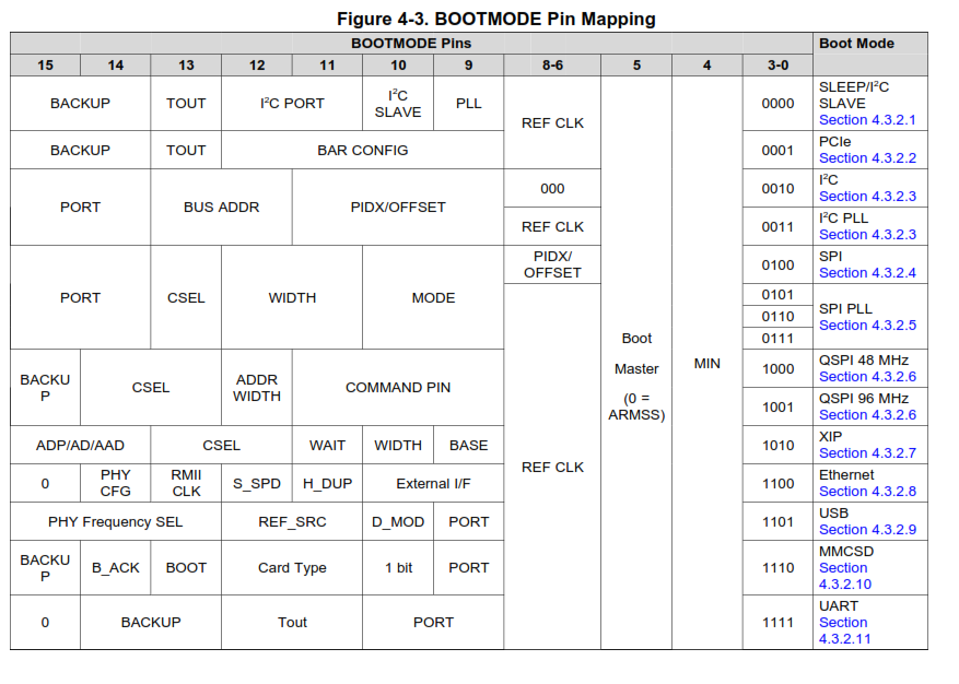
As mentioned in TRM  "section4.3.2 BOOTMODE Pins Description" and figure 4-3 , please elaborate BOOTMODE [4]  and BOOTMODE [5] .

As i want to boot my devce from SPI interface only.My first priority is to use minimum number of pins for boot configuration using QSPI interface FLASH.

THANKS

REGARDS JENS

  • Hi,

    As I said in your other post, BOOTMODE[4] provides the flexibility to NOT connect all 16 bootmode pins.
    Each BOOTMODE provides this minimum configuration that will allow the device to boot in a particular bootmode. This minimum configuration is a combination of BOOTMODE[0-3] pins + some additional pins from BOOTMODE[15:4] for each boot mode.

    For QSPI boot you should see Section 4.3.2.6 QSPI Boot Device Configuration and Table Table 4-9. QSPI Mode Boot Configuration Field Description in the device TRM. I also notified the design team to elaborate if needed.

    Best Regards,
    Yordan

  • Hi Jens,
    Yordan is correct that the min bootmode pin allows you to select a boot mode with the minimum number of pins but that is a bit misleading. While bootmode[15:5] will be ignored, we still expect the customer to include pulling resistors on those pins.
    Regards, Bill