This thread has been locked.

If you have a related question, please click the "Ask a related question" button in the top right corner. The newly created question will be automatically linked to this question.

TMS320C5535: SPI peripheral more than doubles current consumption

Part Number: TMS320C5535

I'm developing on a TMS320C5535 using the XDS110 debugger, the C5000 chip support library, and Code Composer version: 8.3.0.00009. I'm using the C5535 for a low-power application and was surprised to find that the C5535 was using about 70 mA of current when running at 100MHz with 1.3V. When I lower the frequency to 60MHz at 1.05V, the C5535 is drawing 60mA, which is extremely high according to what the datasheet claims. 

After some debugging, I have narrowed down what is making the DSP draw so much current. This is a simplified version of the code I'm running:

int main(void)
{
    /////////////* Variable/Structure Initializations */////////////
    /* System-level variables */
    CSL_Status SYS_status;

    /////////////* System Level Initializations */////////////
    SYS_status = SYS_PLL_LDO_init();
    SYS_status |= SYS_EBSR_init();
    SYS_status |= SYS_GPIO_init();

    
    status = SPI_init();

    // hspi_ADC and spiCfg_ADC are global structs
    hspi_ADC->configured = FALSE;
    hspi_ADC->mode = SPI_CS_NUM_0;
    hspi_ADC->opMode = SPI_POLLING_MODE;

    /* Set the hardware configuration */
    spiCfg_ADC.spiClkDiv  = 20;
    spiCfg_ADC.wLen       = SPI_WORD_LENGTH_32;
    spiCfg_ADC.frLen      = 1;
    spiCfg_ADC.wcEnable   = SPI_WORD_IRQ_DISABLE;
    spiCfg_ADC.fcEnable   = SPI_FRAME_IRQ_DISABLE;
    spiCfg_ADC.csNum      = SPI_CS_NUM_0;
    spiCfg_ADC.dataDelay  = SPI_DATA_DLY_0;
    spiCfg_ADC.csPol      = SPI_CSP_ACTIVE_LOW;
    spiCfg_ADC.clkPol     = SPI_CLKP_LOW_AT_IDLE; // SPI MODE 1
    spiCfg_ADC.clkPh      = SPI_CLK_PH_RISE_EDGE;

    SYS_status |= SPI_config(hspi_ADC, &spiCfg_ADC);


    /////////////* Infinite Loop */////////////
    while (1)
    {


    } // while()
} // main()

This codes causes the DSP at 100MHz to draw 70mA and 60MHz to draw 60mA, which is a crazy amount of current for a low power application.

However, I then comment out the SPI_init():

CSL_Status SYS_SPI_init(){

    CSL_Status status;

    //status = SPI_init();

    hspi_ADS->configured = FALSE;
    hspi_ADS->mode = SPI_CS_NUM_0;
    hspi_ADS->opMode = SPI_POLLING_MODE;

    . 
    . 
    . 

With SPI_init() commented out, the current consumption is now much more reasonable:

100MHz draws about 20mA, 60Mhz draws about 13mA

Why is the SPI peripheral being such a power hog? I even changed the SPI clock frequency from 5MHz to 100kHz, but the large current draw of 70mA/60mA persists. 

One of the ways I tried to get around this was to uninitialized SPI when I'm done sending data using SPI. Even after using SPI_deinit(), the current consumption of the C5535 stays at 70mA/60mA. I'm only able to reduce the current consumption if I don't call SPI_init() at all.

I'm really trying to get as close to 10mA as possible. Are there any suggestions for how I can reduce the power consumption of the SPI peripheral? Is it expected that the SPI peripheral consumes so much current?

Best, 

Eddie

  • Hi Eddie,

    Could you specify what board you are using? If it is a custom board could you provide schematics?
    Also it is important to specify at which point you are measuring the power consumption?

    Regards,
    Tsvetolin Shulev
  • Tsvetolin, 

    Unfortunately, this custom board is for a military application so I cannot post the schematics online. This is a battery powered application, where the battery operates at 6V. However, I'm currently supplying 6V using a DC power supply instead of batteries because this project is still under development.

    I'm measuring the current at the battery holder leads, so I'm measuring current of the whole system on the custom board but only the C5535 is on. All other ICs have been disconnected from the system, so the C5535 is the only IC consuming power. I have TI buck regulators that step down the 6V to 3.3V (DVDDIO/LDOI/DVDDRTC) and 1.3V(CVDDRTC).

    So far, the C5535 has been operating as expected. Like mentioned in the original post, the issue I'm trying to solve is that the C5535 draws 20mA without the SPI peripheral, but then begins drawing 70mA once the SPI peripheral is initialized using SPI_init().

    Best, 

    Eddie

  • Hi Eddie,

    * Can you measure each power rail separately?

    - DVDDIO vs CVDD vs any other supplies

    - to achieve this, remove a component and insert current meter in series

    - or measure voltage drop across a precise resistor in series

    * Have you seen the Power estimation spreadsheet

    - Link to the sheet in http://www.ti.com/lit/pdf/sprabn0 

    - Can plug in the use case to see how closely your measurements match

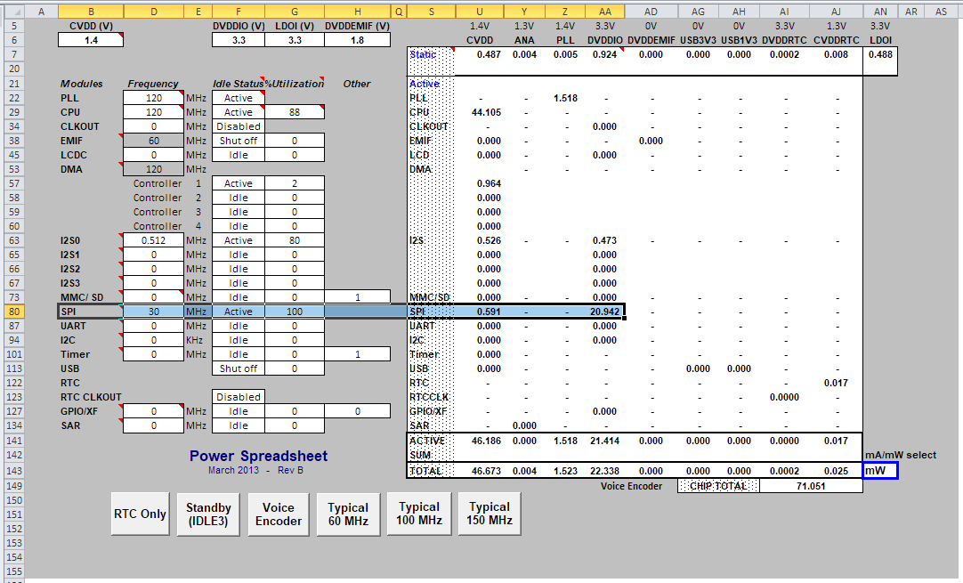
    - The maximum DVDDIO current I was able get from this tool for SPI was 20.942mW (6.346mA * 3.3V)

    - What is the SYSCLK frequency, and resulting SPI_CLK frequency?

    - Does the power increase when SPI activity is on the bus? What is the difference?

    * Refer also to the C5535 schematic review checklist

    - http://www.ti.com/lit/pdf/sprac31

    - In particular floating inputs are capable of increasing DVDDIO power consumption by oscillating through the input threshold region. We advise terminating all IOs with internal or external resistors.

    * Are any other peripherals getting enabled (inadvertently)?

    - Before and after the jump in power consumption, what are the contents of PCGCR1/2? What contents are in EBSR (mux mode selection)?

    * What CSL version are you using?

    - SPI_Init includes a peripheral reset to the PG4 group of peripherals

    - PG4_RST controls the reset to I2S2, I2S3, UART, and SPI.

    - Perhaps the power is actually coming from one of these peripherals.

    - Try resetting all peripherals earlier than SPI_Init, and commenting the peripheral reset step out.

    * Is the power consumption repeatable on multiple boards?

    * What is the IO voltage?

    - There is greater variation across parts in DVDDIO current consumption at 3.3V than at 1.8V.

    * For accurate power measurements when running with emulator, we recommend using the "Free Run" Run mode, and disconnecting the JTAG pod from the board to avoid its power consumption. We also recommend a pull-up on the TDO JTAG pin.

    Summary:

    - Isolate power consumption in system (through the buck? into DVDDIO?)

    - Use lowest IO voltages possible to reduce power

    - Check software peripheral reset impact on power

    - 70mA is very high, check for shorts

    Relevant threads:

    https://e2e.ti.com/support/processors/f/791/t/728102?TMS320VC5505-Estimating-a-part-to-part-deviation-of-3-3V-supply-current

    https://e2e.ti.com/support/processors/f/791/t/728704

    Regards,
    Mark

  • Mark, 

    Thank you for your very detailed reply. I'm currently in the process of taking measurements and figuring out the source of the high current draw. 

    I was testing your theory about PG4 peripherals causing the increase current draw, but I have found that the following line of code is what causes the current draw to spike from 20mA to 70mA:

    	CSL_FINS(sysRegs->PCGCR1, SYS_PCGCR1_SPICG, CSL_SYS_PCGCR1_SPICG_ACTIVE);

    This is the line of code found in SPI_init(void) (the library version number I'm using is 3.08). For some reason the gating of the SPI peripheral is making the current spike. I have already opened the MISO, MOSI, and SPI_CLK traces to see if these lines were possibly shorting, however, the issue persists. 

    The DVDDIO, LDOI, and DVDDRTC pins are all being driven by the same 3.3V regulator. Since they are connected by traces, I cannot give you the current of only DVDDIO. However, I the current consumption of DVDDIO, LDOI, and DVDDRTC together is 28mA BEFORE CSL_SYS_PCGCR1_SPICG_ACTIVE is initiated (28mA seems to line up with what the spreadsheet says). 

    The current consumption of DVDDIO, LDOI, and DVDDRTC together is 82mA AFTER CSL_SYS_PCGCR1_SPICG_ACTIVE is initiated. 

    Some answers for the points you made:

    - The SYSCLK is 100MHz. Although the current draw is high, the DSP still operates normally and doesn't malfunction. I am able to communicate to external ICs with SPI_CLK set at 5MHz. 

    - The current draw stays fixed at ~70mA regardless of the SPI bus being used or not. 

    - Using SPI_deInit() does not help:

        // Current = ~28mA
        SPI_init();
        // Current = ~82mA
        SPI_deInit();
        // Current is still = ~82mA, expected it to be ~28mA again 

    - All unused IO pins have been grounded, there are no unused open pins. 

     - PPMODE = 1, SP1MODE = 1, SP0MODE = 1. These modes have been set and are expected. There is no change after CSL_SYS_PCGCR1_SPICG_ACTIVE is initiated. 

    I hope the information above is helpful to you. I'm still in the process of troubleshooting and will update you on any new findings, but I'm looking for possible shorts as of now. 

    Best, 

    Eddie

  • Hi Eddie,

    Can you read the PCGCR1/2 registers before and after executing the line of code: CSL_FINS(sysRegs->PCGCR1, SYS_PCGCR1_SPICG, CSL_SYS_PCGCR1_SPICG_ACTIVE);

    What is your EBSR register contents?

    I'm just curious if any other peripheral is becoming active somehow.

    Its probably sufficient to measure the combined current of DVDDIO, LDOI, and DVDDRTC.
    Are you using the on-chip LDO for CVDD? Can you measure CVDD separately?

    SPI_CS should have an external pull-up, but I doubt it is causing this high current issue.

    Do you have another board to compare with?

    Regards,
    Mark
  • Eddie said:
    - All unused IO pins have been grounded, there are no unused open pins. 

    This might also be a problem. If the pin is driving out a high and grounded, then lots of current will flow into the GND.

    Which pins are grounded?

    Regards,
    Mark

  • Mark,

    Sorry, I accidentally pressed the "This resolved my issue" button. It's not resolved yet, but we'll get it!

    PCGCR1 = 0x7BFB before CSL_SYS_PCGCR1_SPICG_ACTIVE is initiated. PCGCR1 = 0x7BF9 after the CSL_SYS_PCGCR1_SPICG_ACTIVE is initiated.

    PCGCR2 stays = 0x003B either way. 

    ESBR stays PPMODE = 1, SP1MODE = 1, SP0MODE = 1 either way

    The LDOO pins have been connected directly to the CVDD pins with traces, so unfortunately I can't measure the current going to CVDD for you. 

    To be extra safe I open all the SPI_CS pins to make sure they weren't shorting, but the issue persists.

    Finally, you bring up a good point about the GPIO Pins accidentally being driven to high. I verified that IOOUTDATA1/IOOUTDATA1 = 0x0000, so this probably isn't the issue. It could be possible that I'm driving a non-GPIO pin to ground accidentally, so I'm going to double check the datasheet and make sure there are no non-GPIO pins accidentally being grounded. 

    Best, 

    Eddie

  • Mark,

    I know I may have confused you by pushing the "This resolved my issue" button, but it was accidental. Just a friendly reminder that I have not found a solution for the high current consumption yet and this is still an ongoing issue that I must resolve.

    Best,

    Eddie

  • Hi Eddie,

    Sorry I was out on Friday and playing catch up today.

    I wonder if you can reproduce this current consumption on the C5535 eZdsp.
    It too uses the DSP_LDO to supply CVDD, but it has current measurement devices between DVDDIO, CVDD rails and their supplies to help narrow down the current drain.

    Have you reproduced the high current on another board of yours? I'd like to know if it is consistent across boards.

    PCGCR/2 registers are normal... I'm a little curious to hear the power consumption if you open all the clock gates by clearing all the bits in these registers...

    I understand that this project is sensitive, but is there any way you can provide me with a portion of the schematics with the C5535 sheets?

    Make sure you've read the C5000 DSP-Based Low-Power System Design (www.ti.com/.../sprac07)

    And are following 8.3.3.1 Basic Initialization in the TRM (SPRUH87).

    Regards,
    Mark
  • Mark, 

    I hope your weekend went well, I don't mean to rush you either. 

    If you believe that purchasing a C5535 eZdsp board would be the best course of action to troubleshoot this problem, I can request to have it purchased. Unfortunately, I don't currently have that board. 

    Regarding the clock gates. When I open all of the except for SYSCLKDIS, the high current persists. I even tried the following:

    	CSL_FINS(sysRegs->PCGCR1, SYS_PCGCR1_SPICG, CSL_SYS_PCGCR1_SPICG_ACTIVE);
    	CSL_FINS(sysRegs->PCGCR1, SYS_PCGCR1_SPICG, CSL_SYS_PCGCR1_SPICG_DISABLED);

    I expect the current to go from 20mA to 70mA back to 20mA (I set breakpoints to give myself time to measure the current). However the current never returns to 20mA after disabling the SPI clock gate, it stays at 70mA. 

    One more note. I imported the CSL_SPI_InternalLB_example project into my workspace and chose the appropriate .gel for the c5535(c5505evm_pg20.gel). I found that the same thing happens in the example. After the example initializes: 

    	CSL_FINS(sysRegs->PCGCR1, SYS_PCGCR1_SPICG, CSL_SYS_PCGCR1_SPICG_ACTIVE);

    the current jumps up 30mA. 

    For reference, I've been measuring current across J22 (refer to the schematic).

    I assumed that implementing the dsp_lib would take care of all the initialization steps found 8.3.3.1 SPRUH87, is this not the case?

    Let me know if there's any additional information I can get you. 

    Best, 

    Eddie

  • Hi Eddie,

    I'm still looking at this issue. Thanks for sharing the schematic of the C5535 portion.

    The issue might be related to the resistors to GND. Which ones did you remove?

    The C5535 eZDSP would offer another platform to compare power consumption.

    I'm curious if the SPI uses so much power when you use the alternate mux mode for PPMODE in the EBSR register. There might be a clue.

    Does the current scale with SPI CLK speed or PLL speed?

    Regards,
    Mark
  • Mark, 

    The schematics I sent you represents how the C5535 is currently wired. I have not removed any of the 0ohm resistors yet. This product is still going through its prototype/development phase so the 0ohm resistors are there in case any changes or jumper modifications needs to be made. 

    I have not had any major problems with the C5535 besides this weird SPI power issue. I will consider asking for the C5535 eZDSP if resolving this issue takes longer than expected.

    I did as you suggested and changed the PPMODE from MODE 1 to MODE 6. Unfortunately the same issue persists. 

    The current does scale somewhat with different PLL speeds:

    100MHz: ~22mA without SPI initialized, ~70mA with SPI initialized

    60MHz:   ~13mA without SPI initialized, ~60mA with SPI initialized

    However, changing the SPI CLK speed did not make any noticeable difference in current consumption:

        /* Set the hardware configuration */
        spiCfg_ADS.spiClkDiv  = 20;
        spiCfg_ADS.wLen       = SPI_WORD_LENGTH_32;
        spiCfg_ADS.frLen      = 1;
        spiCfg_ADS.wcEnable   = SPI_WORD_IRQ_DISABLE;
        spiCfg_ADS.fcEnable   = SPI_FRAME_IRQ_DISABLE;
        spiCfg_ADS.csNum      = SPI_CS_NUM_0;
        spiCfg_ADS.dataDelay  = SPI_DATA_DLY_0;
        spiCfg_ADS.csPol      = SPI_CSP_ACTIVE_LOW;
        spiCfg_ADS.clkPol     = SPI_CLKP_LOW_AT_IDLE; // SPI MODE 1
        spiCfg_ADS.clkPh      = SPI_CLK_PH_RISE_EDGE;

    100MHz / 20 = SPI clock of 5MHz

    100MHz / 1000 = SPI clock of 100kHz

    In both cases, the current consumption was still at ~70mA after  SPI_config() was called. 

    Best, 

    Eddie

  • Mark, 

    I found the solution to the problem and can't believe I missed it. 

    Your original theory about a pin being shorted somewhere was correct. I assumed all the SPI_CSx pins are in high impedance when the C5535 powers up. Turns out I was mostly right, but SPI_CS3 is actually HIGH on startup, not high impedance like the other CS pins. I had SPI_CS3 shorted to ground because of of this assumption. Opening the SPI_CS3 pin fixed the issue. 

    As (bad) luck would have it, when I originally checked the CS pins, I only checked CS0, CS1, and CS2. I figured CS3 was going to behave the same so there's no point in checking it, but it was the culprit! 

    Anyways, I appreciate the effort you made to help me resolve this issue, thank you. 

    Best, 

    Eddie

  • Eddie,

    That is great! Thanks for sharing your solution.

    That SPI_CS3 pin is the ONLY one in the High group as documented in 5.7.3.2 Pin Behavior at Reset in the datasheet.

    If you have any further issues, please create a new post.

    Regards,
    Mark