This thread has been locked.

If you have a related question, please click the "Ask a related question" button in the top right corner. The newly created question will be automatically linked to this question.

AM3352: Boot failure

Part Number: AM3352


hi,

    I have some questions in using AM3352.

1. When the RTC of the normal AM3352 is powered up normally, is the C6 pin shown in the figure below output a high level? If the output is low, what could be the cause?

 (1)

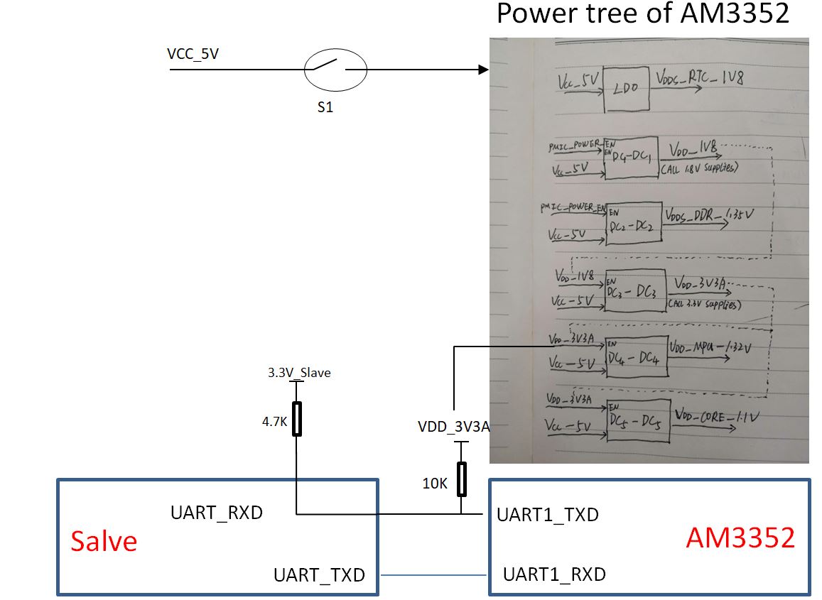
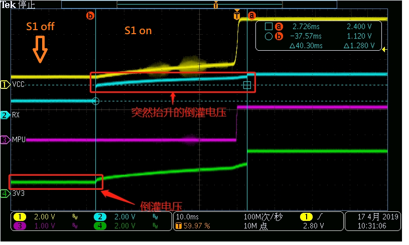
2. In the serial port as shown below, the external data transmission first comes in, and then the AM3352 is powered on. At this time, the pin will always output a low level as shown in 1. What is the cause?
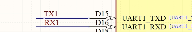
 (2)

thanks.

  • Hi,

    I will answer your second question first:

    It is absolutely forbidden to apply external signals to AM335x I/O pins when the device is unpowered, and also before all supply voltages have fully ramped up and stabilized. Not complying with this requirement may lead to unpredictable device behavior and/or cause permanent damage to the device.

    As for your first question:

    The reason may be either the one explained above, or that you are using the PMIC_POWER_EN signal without having enabled RTC-only mode. This signal should be used only with RTC-only mode enabled (processors.wiki.ti.com/.../AM335x_Schematic_Checklist ).
  • HI, Biser,

       Thanks for you timely feedback. Here are some information that we got last night. This is the block diagram for this problem:

       Firstly, S1 is OFF, Slave connect to AM3352, Due to resistance pull-up of UART in Slave, there is a 1.01V voltage on VDD_3V3A;

      Secondly, S1 is ON, AM3352 start failed in initialize process.

      I have check the datasheet of AM3352, 3.3V isn't the fist voltage in the power on process. Here are two parts our customer want to know:

      1. The effect of 1.01V voltage on VDD_3.3V3A when AM3352 is not power on;

      2. This issue only happened in recent produced boar. We test the board produced last year(same BOM, Layout, test condition), it can start normally.

         Could you give us some advice on this?

  • As I already posted above: It is absolutely forbidden to apply external signals to AM335x I/O pins when the device is unpowered, and also before all supply voltages have fully ramped up and stabilized. Not complying with this requirement may lead to unpredictable device behavior and/or cause permanent damage to the device. Try removing the 10kOhm pullup. It's quite unnecessary anyway. The leaking voltage may start the 1.32V buck converter earlier than expected.
  • Part Number: AM3352

    Hi,

    Remove VDD_3V3A to UART's pullup resistance. When S1 off,  slave connect to AM3352, it still have a 1.01V voltage on VDD_3V3A, you can see the waveform as below:

    What effect does this have on the AM3352? How to prevent it?

    Thanks.

  • I already explained 2 times in my posts above:

    It is absolutely forbidden to apply external signals to AM335x I/O pins when the device is unpowered, and also before all supply voltages have fully ramped up and stabilized. Not complying with this requirement may lead to unpredictable device behavior and/or cause permanent damage to the device.

    To be more precise, when the AM335x device is unpowered maximum external voltage on I/O pins must be <0.3V.