This thread has been locked.

If you have a related question, please click the "Ask a related question" button in the top right corner. The newly created question will be automatically linked to this question.

AM3358: SD card issue

Part Number: AM3358
Other Parts Discussed in Thread: TPS65217

Hello,

I have a custom board with an AM3358BZCZ100 using 2Gb DDR2. I try to boot from the SD-Card and I don't have an eMMC on my board. I have tested my DDR2 memory using CCS and JTAG and a GEL file which is working fine.

One out of 20 times I can see the SPL starting from the SD-Card when I switch on, when I remove the SD-Card every time when I power up I can see the 'C' character printing. I have to switch on the CPU first and then after that inserting the SD-Card, then the first stage bootloader is starting up. It will not go to the second stage bootloader..
I have created the SD-card using the ./create-sdcard.sh. I have 2 different 16Gb Class 10 SDHC micro sd cards.
I use SDK:  ti-processor-sdk-linux-am335x-evm-05.03.00.07

When I load the MLO and U-Boot.img from the serial interface I mostly get the following output from the second stage bootloader (Without SD-Card inserted), then it hangs:

U-Boot 2018.01-00569-g7b4e473-dirty (Apr 13 2019 - 22:58:24 +0400)
CPU  : AM335X-GP rev 2.1
Model: TI AM335x BeagleBone Black                                                                                               
DRAM:  256 MiB
NAND:  0 MiB
MMC:   

And sometimes I get this result and then it hangs:

U-Boot 2018.01-00569-g7b4e473-dirty (Apr 13 2019 - 18:22:58 +0400)
CPU  : AM335X-GP rev
2.1                                                                                 
Model: TI AM335x BeagleBone Black
DRAM:  256 MiB
NAND:  0 MiB
MMC:   OMAP SD/MMC: 00, OMAP SD/MMC: 1
** Bad device mmc 0 **
Using default environment   

When I start from SD-Card I get this (with #DEBUG active) :

U-Boot SPL 2018.01-00569-g7b4e473-dirty (Apr 14 2019 - 18:24:43)                                         
omap24_i2c_findpsc: speed [kHz]: 100 psc: 0xb sscl: 0xd ssch: 0xf                                        
Trying to boot from MMC1
uclass_find_device_by_seq: 0 0
   - -1 -1 'omap_hsmmc'
   - -1 -1 'omap_hsmmc'
   - not found
uclass_find_device_by_seq: 1 0
   - -1 -1 'omap_hsmmc'
   - -1 -1 'omap_hsmmc'
   - not found
malloc_simple: size=x, ptr=40, limit=68: 81f00028
malloc_simple: size=x, ptr=4, limit=6c: 81f00068
uclass_find_device_by_seq: 0 -1
uclass_find_device_by_seq: 0 0
   - -1 -1 'omap_hsmmc'
   - -1 -1 'omap_hsmmc'
   - not found
malloc_simple: size=x, ptr=170, limit=1dc: 81f0006c
malloc_simple: size=x, ptr=40, limit=21c: 81f001dc
malloc_simple: size=x, ptr=4, limit=220: 81f0021c
uclass_find_device_by_seq: 0 -1
uclass_find_device_by_seq: 0 0
   - -1 0 'omap_hsmmc'
   - found
uclass_find_device_by_seq: 0 1
   - -1 0 'omap_hsmmc'
   - -1 -1 'omap_hsmmc'
   - not found
malloc_simple: size=x, ptr=170, limit=390: 81f00220

My pin mux is as follow:

static struct module_pin_mux mmc0_pin_mux[] = {
    {OFFSET(mmc0_dat3), (MODE(0) | RXACTIVE | PULLUP_EN)},    /* MMC0_DAT3 */
    {OFFSET(mmc0_dat2), (MODE(0) | RXACTIVE | PULLUP_EN)},    /* MMC0_DAT2 */
    {OFFSET(mmc0_dat1), (MODE(0) | RXACTIVE | PULLUP_EN)},    /* MMC0_DAT1 */
    {OFFSET(mmc0_dat0), (MODE(0) | RXACTIVE | PULLUP_EN)},    /* MMC0_DAT0 */
    {OFFSET(mmc0_clk), (MODE(0) | RXACTIVE | PULLUP_EN)},    /* MMC0_CLK */
    {OFFSET(mmc0_cmd), (MODE(0) | RXACTIVE | PULLUP_EN)},    /* MMC0_CMD */
    {OFFSET(mcasp0_aclkr), (MODE(4) | RXACTIVE)},        /* MMC0_WP */
    {OFFSET(spi0_cs1), (MODE(7) | RXACTIVE | PULLUP_EN)},    /* GPIO0_6 */
    {-1},
};

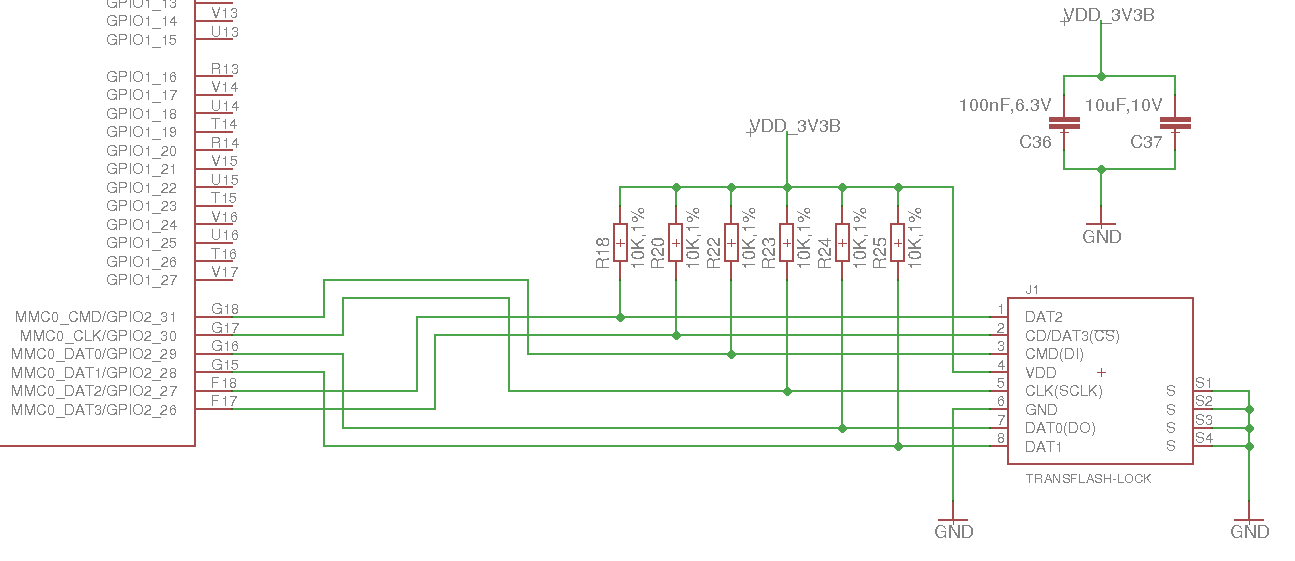
Here is the picture from the drawing that I copied from BBB. Only difference is that I don't have a separate CD pin on my SD-card connector connected:

Anyone has a clue why I get stuck?
Thanks in advance.

  • I actualy for this from printargs in u-boot:
    init_console=if test $board_name = A335_ICE; then setenv console ttyO3,115200n8;else setenv console ttyO0,115200n8;fi;

    So I guess it is printing on ttyO0 and not ttyS0?
  • Only MLO and u-boot.img (and optionally the env file) reside in the boot partition. The zImage and dtb files reside in <rootfs>/boot.

    Please do a "printenv" from u-boot to see all your variables.

    In terms of the console, this is something you need to know from the schematic. Are you using UART0? I imagine that's the case unless you've made changes already to u-boot to account for something else.
  • Yes, I am connected to UART0. I did not modify anything regarding UART in u-boot.

    I actualy got this from printenv in u-boot:
    init_console=if test $board_name = A335_ICE; then setenv console ttyO3,115200n8;else setenv console ttyO0,115200n8;fi;

    So I guess it is printing on ttyO0 and not ttyS0?
    My board is "A335BNLT"
  • It should work with ttyO0 or ttyS0. The A335BNLT corresponds to the BeagleBone Black. So I expect it's loading the dtb corresponding to the BBB. Can you show me the complete "printenv"? I want to see the full environment.

    Also, have you done any customization of the kernel device tree file? You need to make sure it matches your hardware correctly.
  • Brad Griffis said:
    It should work with ttyO0 or ttyS0. The A335BNLT corresponds to the BeagleBone Black. So I expect it's loading the dtb corresponding to the BBB. Can you show me the complete "printenv"? I want to see the full environment.

    Here is the printenv:

    printenv.log
    printenv
    arch=arm
    args_mmc=run finduuid;setenv bootargs console=${console} ${optargs} root=PARTUUID=${uuid} rw rootfstype=${mmcrootfstype}
    baudrate=115200
    board=am335x
    board_name=A335BNLT
    boot_a_script=load ${devtype} ${devnum}:${distro_bootpart} ${scriptaddr} ${prefix}${script}; source ${scriptaddr}
    boot_efi_binary=if fdt addr ${fdt_addr_r}; then bootefi bootmgr ${fdt_addr_r};else bootefi bootmgr ${fdtcontroladdr};fi;load ${devtype} ${devnum}:${distro_bootpart} ${kernel_addr_r} efi/boot/bootarm.efi; if fdt addr ${fdt_addr_r}; then bootefi ${kernel_addr_r} ${fdt_addr_r};else bootefi ${kernel_addr_r} ${fdtcontroladdr};fi
    boot_extlinux=sysboot ${devtype} ${devnum}:${distro_bootpart} any ${scriptaddr} ${prefix}extlinux/extlinux.conf
    boot_fdt=try
    boot_fit=0
    boot_net_usb_start=usb start
    boot_prefixes=/ /boot/
    boot_script_dhcp=boot.scr.uimg
    boot_scripts=boot.scr.uimg boot.scr
    boot_targets=mmc0 legacy_mmc0 mmc1 legacy_mmc1 nand0 pxe dhcp 
    bootcmd=mmc rescan; run findfdt; run init_console; run getuenv; setenv devtype mmc; run loadimage; run loadfdt; run args_mmc; bootz ${loadaddr} - ${fdtaddr}
    bootcmd_dhcp=run boot_net_usb_start; if dhcp ${scriptaddr} ${boot_script_dhcp}; then source ${scriptaddr}; fi;setenv efi_fdtfile ${fdtfile}; if test -z "${fdtfile}" -a -n "${soc}"; then setenv efi_fdtfile ${soc}-${board}${boardver}.dtb; fi; setenv efi_old_vci ${bootp_vci};setenv efi_old_arch ${bootp_arch};setenv bootp_vci PXEClient:Arch:00010:UNDI:003000;setenv bootp_arch 0xa;if dhcp ${kernel_addr_r}; then tftpboot ${fdt_addr_r} dtb/${efi_fdtfile};if fdt addr ${fdt_addr_r}; then bootefi ${kernel_addr_r} ${fdt_addr_r}; else bootefi ${kernel_addr_r} ${fdtcontroladdr};fi;fi;setenv bootp_vci ${efi_old_vci};setenv bootp_arch ${efi_old_arch};setenv efi_fdtfile;setenv efi_old_arch;setenv efi_old_vci;
    bootcmd_legacy_mmc0=setenv mmcdev 0; setenv bootpart 0:2 ; run mmcboot
    bootcmd_legacy_mmc1=setenv mmcdev 1; setenv bootpart 1:2 ; run mmcboot
    bootcmd_mmc0=setenv devnum 0; run mmc_boot
    bootcmd_mmc1=setenv devnum 1; run mmc_boot
    bootcmd_nand=run nandboot
    bootcmd_pxe=run boot_net_usb_start; dhcp; if pxe get; then pxe boot; fi
    bootcount=1
    bootdelay=20
    bootdir=/boot
    bootenvfile=uEnv.txt
    bootfile=zImage
    bootm_size=0x10000000
    bootpart=0:2
    bootscript=echo Running bootscript from mmc${mmcdev} ...; source ${loadaddr}
    console=ttyO0,115200n8
    cpu=armv7
    dfu_alt_info_emmc=rawemmc raw 0 3751936;boot part 1 1;rootfs part 1 2;MLO fat 1 1;MLO.raw raw 0x100 0x200;u-boot.img.raw raw 0x300 0x1000;u-env.raw raw 0x1300 0x200;spl-os-args.raw raw 0x1500 0x200;spl-os-image.raw raw 0x1700 0x6900;spl-os-args fat 1 1;spl-os-image fat 1 1;u-boot.img fat 1 1;uEnv.txt fat 1 1
    dfu_alt_info_mmc=boot part 0 1;rootfs part 0 2;MLO fat 0 1;MLO.raw raw 0x100 0x200;u-boot.img.raw raw 0x300 0x1000;u-env.raw raw 0x1300 0x200;spl-os-args.raw raw 0x1500 0x200;spl-os-image.raw raw 0x1700 0x6900;spl-os-args fat 0 1;spl-os-image fat 0 1;u-boot.img fat 0 1;uEnv.txt fat 0 1
    dfu_alt_info_nand=SPL part 0 1;SPL.backup1 part 0 2;SPL.backup2 part 0 3;SPL.backup3 part 0 4;u-boot part 0 5;u-boot-spl-os part 0 6;kernel part 0 8;rootfs part 0 9
    dfu_alt_info_ram=kernel ram 0x80200000 0x4000000;fdt ram 0x80f80000 0x80000;ramdisk ram 0x81000000 0x4000000
    distro_bootcmd=for target in ${boot_targets}; do run bootcmd_${target}; done
    efi_dtb_prefixes=/ /dtb/ /dtb/current/
    envboot=mmc dev ${mmcdev}; if mmc rescan; then echo SD/MMC found on device ${mmcdev};if run loadbootscript; then run bootscript;else if run loadbootenv; then echo Loaded env from ${bootenvfile};run importbootenv;fi;if test -n $uenvcmd; then echo Ruoning uenvcmd ...;run uenvcmd;fi;fi;fi;
    eth1addr=f0:b5:d1:35:19:ce
    ethact=cpsw
    ethaddr=f0:b5:d1:35:19:cc
    fdt_addr_r=0x88000000
    fdtaddr=0x88000000
    fdtcontroladdr=8df15978
    fdtfile=undefined
    findfdt=if test $board_name = A335BONE; then setenv fdtfile am335x-bone.dtb; fi; if test $board_name = A335BNLT; then setenv fdtfile am335x-boneblack.dtb; fi; if test $board_name = BBBW; then setenv fdtfile am335x-boneblack-wireless.dtb; fi; if test $board_name = BBG1; then setenv fdtfile am335x-bonegreen.dtb; fi; if test $board_name = BBGW; then setenv fdtfile am335x-bonegreen-wireless.dtb; fi; if test $board_name = BBBL; then setenv fdtfile am335x-boneblue.dtb; fi; if test $board_name = A33515BB; then setenv fdtfile am335x-evm.dtb; fi; if test $board_name = A335X_SK; then setenv fdtfile am335x-evmsk.dtb; fi; if test $board_name = A335_ICE && test $ice_mii = rmii; then setenv fdtfile am335x-icev2.dtb; fi; if test $board_name = A335_ICE && test $ice_mii = mii; then setenv fdtfile am335x-icev2-prueth.dtb; fi; if test $fdtfile = undefined; then echo WARNING: Could not determine device tree to use; fi; 
    finduuid=part uuid mmc ${bootpart} uuid
    fit_bootfile=fitImage
    fit_loadaddr=0x87000000
    getuenv=if mmc rescan; then if run loadbootenv; then run importbootenv; fi; fi;
    ice_mii=mii
    importbootenv=echo Importing environment from mmc${mmcdev} ...; env import -t ${loadaddr} ${filesize}
    init_console=if test $board_name = A335_ICE; then setenv console ttyO3,115200n8;else setenv console ttyO0,115200n8;fi;
    ip_method=none
    kernel_addr_r=0x82000000
    load_efi_dtb=load ${devtype} ${devnum}:${distro_bootpart} ${fdt_addr_r} ${prefix}${efi_fdtfile}
    loadaddr=0x82000000
    loadbootenv=fatload mmc ${mmcdev} ${loadaddr} ${bootenvfile}
    loadbootscript=load mmc ${mmcdev} ${loadaddr} boot.scr
    loadfdt=load ${devtype} ${bootpart} ${fdtaddr} ${bootdir}/${fdtfile}
    loadfit=run args_mmc; bootm ${loadaddr}#${fdtfile};
    loadimage=load ${devtype} ${bootpart} ${loadaddr} ${bootdir}/${bootfile}
    loadramdisk=load mmc ${mmcdev} ${rdaddr} ramdisk.gz
    mmc_boot=if mmc dev ${devnum}; then setenv devtype mmc; run scan_dev_for_boot_part; fi
    mmcboot=mmc dev ${mmcdev}; setenv devnum ${mmcdev}; setenv devtype mmc; if mmc rescan; then echo SD/MMC found on device ${mmcdev};if run loadimage; then if test ${boot_fit} -eq 1; then run loadfit; else ruo mmcloados;fi;fi;fi;
    mmcdev=0
    mmcloados=run args_mmc; if test ${boot_fdt} = yes || test ${boot_fdt} = try; then if run loadfdt; then bootz ${loadaddr} - ${fdtaddr}; else if test ${boot_fdt} = try; then bootz; else echo WARN: Cannot load the DT; fi; fi; else bootz; fi;
    mmcrootfstype=ext4 rootwait
    mtdids=nand0=nand.0
    mtdparts=mtdparts=nand.0:128k(NAND.SPL),128k(NAND.SPL.backup1),128k(NAND.SPL.backup2),128k(NAND.SPL.backup3),256k(NAND.u-boot-spl-os),1m(NAND.u-boot),128k(NAND.u-boot-env),128k(NAND.u-boot-env.backup1),8m(NAND.kernel),-(NAND.file-system)
    nandargs=setenv bootargs console=${console} ${optargs} root=${nandroot} rootfstype=${nandrootfstype}
    nandboot=echo Booting from nand ...; run nandargs; nand read ${fdtaddr} NAND.u-boot-spl-os; nand read ${loadaddr} NAND.kernel; bootz ${loadaddr} - ${fdtaddr}
    nandroot=ubi0:rootfs rw ubi.mtd=NAND.file-system,2048
    nandrootfstype=ubifs rootwait=1
    netargs=setenv bootargs console=${console} ${optargs} root=/dev/nfs nfsroot=${serverip}:${rootpath},${nfsopts} rw ip=dhcp
    netboot=echo Booting from network ...; setenv autoload no; dhcp; run netloadimage; run netloadfdt; run netargs; bootz ${loadaddr} - ${fdtaddr}
    netloadfdt=tftp ${fdtaddr} ${fdtfile}
    netloadimage=tftp ${loadaddr} ${bootfile}
    nfsopts=nolock
    partitions=uuid_disk=${uuid_gpt_disk};name=rootfs,start=2MiB,size=-,uuid=${uuid_gpt_rootfs}
    pxefile_addr_r=0x80100000
    ramargs=setenv bootargs console=${console} ${optargs} root=${ramroot} rootfstype=${ramrootfstype}
    ramboot=echo Booting from ramdisk ...; run ramargs; bootz ${loadaddr} ${rdaddr} ${fdtaddr}
    ramdisk_addr_r=0x88080000
    ramroot=/dev/ram0 rw
    ramrootfstype=ext2
    rdaddr=0x88080000
    rootpath=/export/rootfs
    scan_dev_for_boot=echo Scanning ${devtype} ${devnum}:${distro_bootpart}...; for prefix in ${boot_prefixes}; do run scan_dev_for_extlinux; run scan_dev_for_scripts; done;run scan_dev_for_efi;
    scan_dev_for_boot_part=part list ${devtype} ${devnum} -bootable devplist; env exists devplist || setenv devplist 1; for distro_bootpart in ${devplist}; do if fstype ${devtype} ${devnum}:${distro_bootpart} bootfstype; then run scan_dev_for_boot; fi; done
    scan_dev_for_efi=setenv efi_fdtfile ${fdtfile}; if test -z "${fdtfile}" -a -n "${soc}"; then setenv efi_fdtfile ${soc}-${board}${boardver}.dtb; fi; for prefix in ${efi_dtb_prefixes}; do if test -e ${devtype} ${devnum}:${distro_bootpart} ${prefix}${efi_fdtfile}; then run load_efi_dtb; fi;done;if test -e ${devtype} ${devnum}:${distro_bootpart} efi/boot/bootarm.efi; then echo Found EFI removable media binary efi/boot/bootarm.efi; run boot_efi_binary; echo EFI LOAD FAILED: continuing...; fi; setenv efi_fdtfile
    scan_dev_for_extlinux=if test -e ${devtype} ${devnum}:${distro_bootpart} ${prefix}extlinux/extlinux.conf; then echo Found ${prefix}extlinux/extlinux.conf; run boot_extlinux; echo SCRIPT FAILED: continuing...; fi
    scan_dev_for_scripts=for script in ${boot_scripts}; do if test -e ${devtype} ${devnum}:${distro_bootpart} ${prefix}${script}; then echo Found U-Boot script ${prefix}${script}; ruo boot_a_script; echo SCRIPT FAILED: continuing...; fi; done
    scriptaddr=0x80000000
    soc=am33xx
    spiargs=setenv bootargs console=${console} ${optargs} root=${spiroot} rootfstype=${spirootfstype}
    spiboot=echo Booting from spi ...; run spiargs; sf probe ${spibusno}:0; sf read ${loadaddr} ${spisrcaddr} ${spiimgsize}; bootz ${loadaddr}
    spibusno=0
    spiimgsize=0x362000
    spiroot=/dev/mtdblock4 rw
    spirootfstype=jffs2
    spisrcaddr=0xe0000
    static_ip=${ipaddr}:${serverip}:${gatewayip}:${netmask}:${hostname}::off
    stderr=serial@44e09000
    stdin=serial@44e09000
    stdout=serial@44e09000
    update_to_fit=setenv loadaddr ${fit_loadaddr}; setenv bootfile ${fit_bootfile}
    usb_boot=usb start; if usb dev ${devnum}; then setenv devtype usb; run scan_dev_for_boot_part; fi
    usbnet_devaddr=f0:b5:d1:35:19:cc
    vendor=ti
    ver=U-Boot 2018.01-00569-g7b4e473-dirty (Apr 26 2019 - 20:02:28 +0400)
    
    Environment size: 9999/131068 bytes
    => 

    Brad Griffis said:
    Also, have you done any customization of the kernel device tree file? You need to make sure it matches your hardware correctly.

    I did, because I do not have an CD pin on my sd-card slot.
    Here is the modification in am335x-bone-common.dtsi.
    Is this also the kernel device tree? Or only for u-boot itself.

    modification.log
    diff --git a/arch/arm/dts/am335x-bone-common.dtsi b/arch/arm/dts/am335x-bone-common.dtsi
    index 40a3c35..683b481 100644
    --- a/arch/arm/dts/am335x-bone-common.dtsi
    +++ b/arch/arm/dts/am335x-bone-common.dtsi
    @@ -387,8 +387,9 @@
     	status = "okay";
     	bus-width = <0x4>;
     	pinctrl-names = "default";
    +    broken-cd;
     	pinctrl-0 = <&mmc1_pins>;
    -	cd-gpios = <&gpio0 6 GPIO_ACTIVE_LOW>;
    +	/* cd-gpios = <&gpio0 6 GPIO_ACTIVE_LOW>; */
     };
     
     &aes {
    

    My Muc.c looks like:

    static struct module_pin_mux mmc0_pin_mux[] = {
    	{OFFSET(mmc0_dat3), (MODE(0) | RXACTIVE | PULLUP_EN)},	/* MMC0_DAT3 */
    	{OFFSET(mmc0_dat2), (MODE(0) | RXACTIVE | PULLUP_EN)},	/* MMC0_DAT2 */
    	{OFFSET(mmc0_dat1), (MODE(0) | RXACTIVE | PULLUP_EN)},	/* MMC0_DAT1 */
    	{OFFSET(mmc0_dat0), (MODE(0) | RXACTIVE | PULLUP_EN)},	/* MMC0_DAT0 */
    	{OFFSET(mmc0_clk), (MODE(0) | RXACTIVE | PULLUP_EN)},	/* MMC0_CLK */
    	{OFFSET(mmc0_cmd), (MODE(0) | RXACTIVE | PULLUP_EN)},	/* MMC0_CMD */
    	{OFFSET(mcasp0_aclkr), (MODE(4) | RXACTIVE)},		/* MMC0_WP */
    	/* {OFFSET(spi0_cs1), (MODE(7) | RXACTIVE | PULLUP_EN)},   GPIO0_6 */
    	{-1},
    };
    

    Schematic:

  • Please also not that I don't have a FIT image, as when I started it was on by default, but I had some issues with that. I really don't know if this is required.
    CONFIG_SPL_LOAD_FIT=n
  • The modification you showed is from the u-boot dts file. In my experience, u-boot only uses the device tree content in a limited way (i.e. as opposed to the kernel which EXTENSIVELY uses the dts data). When the loadfdt command runs from u-boot, it's grabbing am335x-boneblack.dtb from the file system partition (rootfs) inside the boot directory. I'm going to restate this in another way to make sure we're on the same page. When I say the "boot directory" I am NOT referrring to the boot partition. I'm talking about the rootfs partition that holds the complete Linux file system. There's a directory in there called "boot" that has the device tree and zImage files. Can you confirm you're with me on that? It's a crucial point.

    Correspondingly, to update the dtb that is in the rootfs/boot directory, you need to make updates in LINUX to the arch/arm/boot/dts/am335x-boneblack.dts file.
  • By the way, what PMIC are you using? And what board did you model your design after? The BBB uses DDR3, so it doesn't seem like you were using that design, which leads me to wonder why you're telling u-boot that you're a BBB. I'm wondering if this relates to some of the odd things you're seeing.
  • Brad Griffis said:
    Can you confirm you're with me on that? It's a crucial point.

    Understood. I was actually aware of the difference between "boot directory" and "boot partition". The boot directory contains the am335x-boneblack.dts that need to be updated somehow.

    Brad Griffis said:
    Correspondingly, to update the dtb that is in the rootfs/boot directory, you need to make updates in LINUX to the arch/arm/boot/dts/am335x-boneblack.dts file.

    I do not understand this part completely. I updated the am335x-bone-common.dtsi. After compiling u-boot, do I need to copy the file "arch/arm/boot/dts/am335x-boneblack.dts" to the boot directory and overwrite the old file?

  • Brad Griffis said:
    By the way, what PMIC are you using? And what board did you model your design after? The BBB uses DDR3, so it doesn't seem like you were using that design, which leads me to wonder why you're telling u-boot that you're a BBB. I'm wondering if this relates to some of the odd things you're seeing.

    Yes, you re right. actually I started as a reference to BBB. then I swapped to DDR2 but that requires to use a TPS65217B. So my DDR uses 1.8 volt. So yes, it is not completely a BBB. For this difference I took in account the startup sequence for where some 1.8Volt pins need to be connected to. Is there another board I can define it as instead?

  • J E said:
    I do not understand this part completely. I updated the am335x-bone-common.dtsi. After compiling u-boot, do I need to copy the file "arch/arm/boot/dts/am335x-boneblack.dts" to the boot directory and overwrite the old file?

    Have you used the top-level makefile before?  In the root directory of the SDK (i.e. two levels higher than where u-boot and kernel reside) there is a makefile.  There's a rule that enables you to run "make linux-dtbs" that will build the dtb's inside Linux.  So for example, this will build many dtb's, one of them in this bunch relates to this file:

    ~/ti-processor-sdk-linux-am335x-evm-05.03.00.07/board-support/linux-4.14.79+gitAUTOINC+e669d52447-ge669d52447/arch/arm/boot/dts$ vim am335x-boneblack.dts

    I gave the complete path to emphasize that it's inside the kernel and not inside u-boot.  Hopefully that makes sense.

    And here's a highly condensed version of "make linux-dtbs":

    brad@brad-XPS-15-9560:~/ti-processor-sdk-linux-am335x-evm-05.03.00.07$ make linux-dtbs
    =====================================
    Building the Linux Kernel DTBs
    =====================================
    make -C /home/brad/ti-processor-sdk-linux-am335x-evm-05.03.00.07/board-support/linux-4.14.79+gitAUTOINC+e669d52447-ge669d52447 ARCH=arm CROSS_COMPILE=/home/brad/ti-processor-sdk-linux-am335x-evm-05.03.00.07/linux-devkit/sysroots/x86_64-arago-linux/usr/bin/arm-linux-gnueabihf- tisdk_am335x-evm_defconfig
    make[1]: Entering directory '/home/brad/ti-processor-sdk-linux-am335x-evm-05.03.00.07/board-support/linux-4.14.79+gitAUTOINC+e669d52447-ge669d52447'
    HOSTCC scripts/basic/fixdep
    HOSTCC scripts/kconfig/conf.o
    SHIPPED scripts/kconfig/zconf.tab.c
    SHIPPED scripts/kconfig/zconf.lex.c
    HOSTCC scripts/kconfig/zconf.tab.o
    HOSTLD scripts/kconfig/conf
    #
    # configuration written to .config
    #

    make[1]: Entering directory '/home/brad/ti-processor-sdk-linux-am335x-evm-05.03.00.07/board-support/linux-4.14.79+gitAUTOINC+e669d52447-ge669d52447'

    CHK scripts/mod/devicetable-offsets.h
    DTC arch/arm/boot/dts/am335x-boneblack.dtb

  • J E said:
    Yes, you re right. actually I started as a reference to BBB. then I swapped to DDR2 but that requires to use a TPS65217B. So my DDR uses 1.8 volt. So yes, it is not completely a BBB. For this difference I took in account the startup sequence for where some 1.8Volt pins need to be connected to. Is there another board I can define it as instead?

    Were you using this app note as part of your design:

    Powering the AM335x with the TPS65217x
    http://www.ti.com/lit/slvu551

    Specifically, please look at Section 5, Connections Diagram for TPS65217B and AM335x.  Does your rail topology precisely follow that hookup? 

  • Nice, I did not use the top-level makefile before.
    So I did compile the am335x-boneblack.dts in the LINUX folder I can see.
    But before I compile, which file need to be updated first? I don't see it takes the information from the u-boot directory to properly construct the am335x-boneblack.dts.
    After the compilation, I copy this file directly to the "boot directory", right?
  • Brad Griffis said:

    Were you using this app note as part of your design:

    Powering the AM335x with the TPS65217x
    http://www.ti.com/lit/slvu551

    Specifically, please look at Section 5, Connections Diagram for TPS65217B and AM335x.  Does your rail topology precisely follow that hookup? 

    Wow, this is actually very good information. I did not use this document. I took parts from the BBB instead. I will have a very close look tomorrow in detail.

  • J E said:
    Nice, I did not use the top-level makefile before.
    But before I compile, which file need to be updated first? I don't see it takes the information from the u-boot directory to properly construct the am335x-boneblack.dts.

    Unfortunately, this is not directly tied into u-boot, i.e. there's not a single common file that is shared between them.  In general though, I find the kernel dts is really the main one that needs to be updated.

    J E said:
    After the compilation, I copy this file directly to the "boot directory", right?

    Correct, the resulting dtb should go into <rootfs>/boot.

  • J E said:

    Brad Griffis

    Were you using this app note as part of your design:

    Powering the AM335x with the TPS65217x
    http://www.ti.com/lit/slvu551

    Specifically, please look at Section 5, Connections Diagram for TPS65217B and AM335x.  Does your rail topology precisely follow that hookup? 

    Wow, this is actually very good information. I did not use this document. I took parts from the BBB instead. I will have a very close look tomorrow in detail.

    Here's what I suggest...  Please make a spreadsheet that looks something along the lines of Table 3.  Though add another column showing how you have things hooked up.  I would suggest having the AM335x rails on the left column, and then for each rail of the AM335x you can insert which rail you have it connected to.

  • So is it common to just copy the data from file: "<Processor SDK>/board-support/u-boot-<version>/arch/arm/dts/am335x-bone-common.dtsi" to "~/ti-processor-sdk-linux-am335x-evm-05.03.00.07/board-support/linux-4.14.79+gitAUTOINC+e669d52447-ge669d52447/arch/arm/boot/dts/am335x-boneblack.dts"

    and then compile in the top-level makefile using "make linux-dtbs"

    and then copy the am335x-boneblack.dtb to the "boot directory" on the sd-card?

    At the moment there is almost nothing in the file: "~/ti-processor-sdk-linux-am335x-evm-05.03.00.07/board-support/linux-4.14.79+gitAUTOINC+e669d52447-ge669d52447/arch/arm/boot/dts/am335x-boneblack.dts"

  • Brad Griffis said:
    Brad Griffis

    Were you using this app note as part of your design:

    Powering the AM335x with the TPS65217x
    http://www.ti.com/lit/slvu551

    Specifically, please look at Section 5, Connections Diagram for TPS65217B and AM335x.  Does your rail topology precisely follow that hookup?

    Wow, this is actually very good information. I did not use this document. I took parts from the BBB instead. I will have a very close look tomorrow in detail.

    Here's what I suggest...  Please make a spreadsheet that looks something along the lines of Table 3.  Though add another column showing how you have things hooked up.  I would suggest having the AM335x rails on the left column, and then for each rail of the AM335x you can insert which rail you have it connected to.

    Thanks! That is a very good plan to check everything is consistent.

  • J E said:
    So is it common to just copy the data from file: "<Processor SDK>/board-support/u-boot-<version>/arch/arm/dts/am335x-bone-common.dtsi" to "~/ti-processor-sdk-linux-am335x-evm-05.03.00.07/board-support/linux-4.14.79+gitAUTOINC+e669d52447-ge669d52447/arch/arm/boot/dts/am335x-boneblack.dts"

    and then compile in the top-level makefile using "make linux-dtbs"

    No.  If anything, I would consider doing the opposite.  All your device tree work should be done in Linux.  It's possible you might be able to reuse your Linux devicetree for u-boot, but in general u-boot doesn't know what to do with most of it.  Typically, these two device trees are handled independently.  The u-boot device tree only needs enough to boot the kernel.  Most of your effort should be focused on the kernel device tree.

    I'll further elaborate that in u-boot most board-specific detail is still handled in the board.c file.  In Linux all the board-specific detail is handled in the dts.  I think u-boot is trying to emulate u-boot but it's nowhere close in my opinion.

    J E said:
    At the moment there is almost nothing in the file: "~/ti-processor-sdk-linux-am335x-evm-05.03.00.07/board-support/linux-4.14.79+gitAUTOINC+e669d52447-ge669d52447/arch/arm/boot/dts/am335x-boneblack.dts"

    It includes other files.  Most of the "real" code is in the files it includes like am335x-bone-common.dtsi, etc.

  • Thanks a lot. It is more clear not and I understand how to configure, build and where to copy the file.

    I was starting with defining the MMC1 and UART0 so that I would get some output.

    What I expect is after that the kernel will give me information what is happening but it seems to get stuck when it tries to load the kernel. After around 20 seconds the board automatically resets and reboot.

    Is there some way to debug this stage of hanging?

    I know that for a test I can load it in over UART, but after the zImage I need to load a ramfs file into the board which I don't have. I tried to search how to build it, is it true that 'ramfs' is equal to an 'uImage' by definition?

  • The high level detail is that you need to use "earlyprintk" to get detail as to what's failing. You may need to start an independent thread on that topic. I would try to get it working using an already-working BBB first. Then take that procedure and apply to your own hardware, and hopefully that gives us some insight into what's happening.

    Some other thoughts would be to just connect to the Cortex A8 and "look around", e.g. where is the code, etc. Have you measured your various voltage rails? We need to make sure everything is at the appropriate voltage. We may need to go back to your clock tree dump to see what voltage the MPU was operating to make sure the voltage is correct.
  • Brad Griffis said:
    The high level detail is that you need to use "earlyprintk" to get detail as to what's failing. You may need to start an independent thread on that topic. I would try to get it working using an already-working BBB first. Then take that procedure and apply to your own hardware, and hopefully that gives us some insight into what's happening.

    Yes, let's forget this point now. I will make a separate thread for this later after I checked the power.

    Brad Griffis said:
    Some other thoughts would be to just connect to the Cortex A8 and "look around", e.g. where is the code, etc. Have you measured your various voltage rails? We need to make sure everything is at the appropriate voltage. We may need to go back to your clock tree dump to see what voltage the MPU was operating to make sure the voltage is correct.

    Yes, good point. I will check the power rails tonight, Thanks.

  • Brad Griffis said:
    Have you measured your various voltage rails?

    I have finished the table with the voltage rails:
    Power_lines.xlsx

    I also have scope measurements from the voltage lines, from 10 days ago. The board has not changed so it is still valid. This is measured with CPU on 600 MHz.
    Signal "VDD_3V3A" from the pictures is representing the LDO3 and LDO4 together, as mentioned in the excel sheet they are linked together.
    Signal "VDD_3V3B"  is the output of a TL5209DR which is powered by "VDD_3V3A". The purpuse is to have a current limiter, same as used for BBB. "VDD_3V3B" is connected to the SD-Card slot and J-TAG header.
    8203.V2.0.2 Voltage pictures.zip

    The voltage on VDD_CORE and VDD_MPU is slightly higher then expected, also VDD_3V3B tot he SD-Card is 100mV higher then expected.

    I also connected the BBB and put my CPU of the custom board to 1GHz at startup and then interrupt the u-boot so it is not getting into a crashing loop. I feel that my CPU is getting much warmer then the BBB which indicates something must be unstable or wrong connected.

  • FYI, I looked at your *.rd1 file that you provided earlier.  The MPU was running at 500 MHz in that particular instance.  That strikes me as a bit strange, unless you deliberately are setting it to that speed.

    J E said:
    Signal "VDD_3V3A" from the pictures is representing the LDO3 and LDO4 together, as mentioned in the excel sheet they are linked together.
    Signal "VDD_3V3B"  is the output of a TL5209DR which is powered by "VDD_3V3A". The purpuse is to have a current limiter, same as used for BBB. "VDD_3V3B" is connected to the SD-Card slot and J-TAG header.
    (Please visit the site to view this file)

    This is concerning that these voltages are all so high.  They are too high and we need to get that fixed...

    J E said:
    The voltage on VDD_CORE and VDD_MPU is slightly higher then expected, also VDD_3V3B tot he SD-Card is 100mV higher then expected.

    These two rails get configured inside u-boot.  I recall noticing this behavior in the past, i.e. u-boot configuring them too high for some reason.  It is easily corrected, so I'm not really concerned about those rails as much.

    J E said:
    I feel that my CPU is getting much warmer then the BBB which indicates something must be unstable or wrong connected.

    I agree.  It might be related to those 3.3V rails being too high.  It would be good to get that figured out, and if the issue still exists look more carefully elsewhere.

  • Brad Griffis said:
    FYI, I looked at your *.rd1 file that you provided earlier.  The MPU was running at 500 MHz in that particular instance.  That strikes me as a bit strange, unless you deliberately are setting it to that speed.

    I realize now that the GEL file for OPP100 is setting the speed to 500MHz. The scope mesurements are still in 600MHz, but the .RD1 files are in 500MHz because I used the GEL file.

    hotmenu ARM_OPP100_Config()
    {
    GEL_TextOut("****  AM335x ALL PLL Config for OPP == OPP100 is in progress ......... \n","Output",1,1,1);
    GetInputClockFrequency();
    if(CLKIN==24)
    {
       MPU_PLL_Config(  CLKIN, 23, 500, 1);
       CORE_PLL_Config( CLKIN, 23, 1000, 10, 8, 4);
       DDR_PLL_Config(  CLKIN, 23, 133, 1);
       PER_PLL_Config(  CLKIN, 23, 960, 5);
       DISP_PLL_Config( CLKIN, 23, 48, 1);
       GEL_TextOut("****  AM335x ALL ADPLL Config for OPP == OPP100 is Done ......... \n","Output",1,1,1);
    }
    else 
       GEL_TextOut("****  AM335x PLL Config failed!!  Check SYSBOOT[15:14] for proper input freq config \n","Output",1,1,1);
    }

    Brad Griffis said:
    J E
    Signal "VDD_3V3A" from the pictures is representing the LDO3 and LDO4 together, as mentioned in the excel sheet they are linked together.
    Signal "VDD_3V3B"  is the output of a TL5209DR which is powered by "VDD_3V3A". The purpuse is to have a current limiter, same as used for BBB. "VDD_3V3B" is connected to the SD-Card slot and J-TAG header.
    (Please visit the site to view this file)

    This is concerning that these voltages are all so high.  They are too high and we need to get that fixed...

    Only the voltage that is going to the SDcard and JTag header is 100mV too high. This is signal VDD_3V3B which is 3,4Volt. The signal VDD_3V3A which is going to the CPU is actually 3,34 volt.
    Why I think the VDD_3V3B is too high is the resistors that regulate the output, see the picture below. 5 Volt is going into this chip. I think I need to have a close look at the resistors, or just remove this chip as it seems kind of pointless in the end.

    Brad Griffis said:
    J E
    The voltage on VDD_CORE and VDD_MPU is slightly higher then expected, also VDD_3V3B tot he SD-Card is 100mV higher then expected.

    These two rails get configured inside u-boot.  I recall noticing this behavior in the past, i.e. u-boot configuring them too high for some reason.  It is easily corrected, so I'm not really concerned about those rails as much.

    How can we adjust these voltages for VDD_CORE and VDD_MPU?

  • J E said:
    How can we adjust these voltages for VDD_CORE and VDD_MPU?

    For BeagleBone variants, the scale_vcores_bone() function in board/ti/am335x/board.c has this:

    /* Set DCDC3 (CORE) voltage to 1.10V */
    if (tps65217_voltage_update(TPS65217_DEFDCDC3,
    TPS65217_DCDC_VOLT_SEL_1100MV)) {
    puts("tps65217_voltage_update failure\n");
    return;
    }

    /* Set DCDC2 (MPU) voltage */
    if (tps65217_voltage_update(TPS65217_DEFDCDC2, mpu_vdd)) {
    puts("tps65217_voltage_update failure\n");
    return;
    }

    To fully understand what's happening look first at the scale_vcores() function in that same file.  It first calls am335x_get_efuse_mpu_max_freq(cdev) which uses the e-fuses to determine the highest supported frequency of the device in use (i.e. it dynamically interrogates what speed grade is being used).

    I recommend deleting these lines entirely:


    /*
    * Override what we have detected since we know if we have
    * a Beaglebone Black it supports 1GHz.
    */
    if (board_is_bone_lt())
    freq = MPUPLL_M_1000;

    That statement is there because some of the early BeagleBone Black boards used Rev 2.0 silicon which didn't have the fuses blown to determine the speed grade.  So in order to have those very early BBB's operate at 1 GHz, that statement is in there...  Or alternatively, you could leverage that statement to stuff in whatever frequency you prefer.

    What version of the SDK are you using?  The DCDC3 voltage (in SDK 5.03) should already be 1.100V.  Are you on an older version that lacks that change?

  • I am using "ti-processor-sdk-linux-am335x-evm-05.03.00.07".

    At the moment I have the following code for "scale_vcores_bone".

    	/*
    	 * On Beaglebone White we need to ensure we have AC power
    	 * before increasing the frequency.
    	 */
    	//if (bone_not_connected_to_ac_power())
    	//	freq = MPUPLL_M_600;
    
    	/*
    	 * Override what we have detected since we know if we have
    	 * a Beaglebone Black it supports 1GHz.
    	 */
    	if (board_is_bone_lt())
            freq = MPUPLL_M_600;
    
    
    	switch (freq) {
    	case MPUPLL_M_1000:
    		mpu_vdd = TPS65217_DCDC_VOLT_SEL_1325MV;
    		usb_cur_lim = TPS65217_USB_INPUT_CUR_LIMIT_1800MA;
    		break;
    	case MPUPLL_M_800:
    		mpu_vdd = TPS65217_DCDC_VOLT_SEL_1275MV;
    		usb_cur_lim = TPS65217_USB_INPUT_CUR_LIMIT_1300MA;
    		break;
    	case MPUPLL_M_720:
    		mpu_vdd = TPS65217_DCDC_VOLT_SEL_1200MV;
    		usb_cur_lim = TPS65217_USB_INPUT_CUR_LIMIT_1300MA;
    		break;
    	case MPUPLL_M_600:
    	case MPUPLL_M_500:
    	case MPUPLL_M_300:
    	default:
    		mpu_vdd = TPS65217_DCDC_VOLT_SEL_1100MV;
    		usb_cur_lim = TPS65217_USB_INPUT_CUR_LIMIT_1300MA;
    		break;
    	}
    
    	if (tps65217_reg_write(TPS65217_PROT_LEVEL_NONE,
    			       TPS65217_POWER_PATH,
    			       usb_cur_lim,
    			       TPS65217_USB_INPUT_CUR_LIMIT_MASK))
    		puts("tps65217_reg_write failure\n");
    
    	/* Set DCDC3 (CORE) voltage to 1.10V */
    	if (tps65217_voltage_update(TPS65217_DEFDCDC3,
    				    TPS65217_DCDC_VOLT_SEL_1100MV)) {
    		puts("tps65217_voltage_update failure\n");
    		return;
    	}
    
    	/* Set DCDC2 (MPU) voltage */
    	if (tps65217_voltage_update(TPS65217_DEFDCDC2, mpu_vdd)) {
    		puts("tps65217_voltage_update failure\n");
    		return;
    	}

    I noticed that for the TPS65217 the following defines are available from the header file:
    #define TPS65217_DCDC_VOLT_SEL_950MV          0x02
    #define TPS65217_DCDC_VOLT_SEL_1100MV        0x08
    #define TPS65217_DCDC_VOLT_SEL_1125MV        0x09
    #define TPS65217_DCDC_VOLT_SEL_1200MV        0x0c
    #define TPS65217_DCDC_VOLT_SEL_1275MV        0x0F
    #define TPS65217_DCDC_VOLT_SEL_1325MV        0x11

    So if the voltage is slightly too high I am not sure if I need to check the hardware or the software at this point. Maybe some grounding not ok?
    At 600 MHz:
    VDD_MPU = OPP100 should be 1.1 Volt.  I measured 1.142 volt.
    VDD_CORE = Should be 1,1 Volt.   I measured 1,14 Volt.

  • J E said:
    if (tps65217_voltage_update(TPS65217_DEFDCDC3, TPS65217_DCDC_VOLT_SEL_1100MV)) { puts("tps65217_voltage_update failure\n"); return; }

    Does changing this to use TPS65217_DCDC_VOLT_SEL_1125MV cause your voltage to correspondingly increase by 25 mV?  It's not clear whether some other code is running, or perhaps something else overwrites the voltage, or maybe the PMIC output is just not correct.  I'd like to see some signs that things are correlated as expected.  If it does indeed bump up by 25 mV, perhaps you should start a thread on the PMIC forum to understand why the voltage is incorrect.  Perhaps you have an issue with how you've arranged your passives (wrong topology, wrong value, etc.) or maybe there's some kind of layout issue.  In general I have been through a lot of designs with this PMIC and not seen this sort of behavior.

  • Yeah, I will start to see if the voltage increases 25mV per step. I will put the scope on it tomorrow.
    I asume this voltage regulation is only done in the SPL and not after. Perhaps when linux boots eventually but I did not get that far yet.
  • I have checked. I tested on 600MHz and 1GHz. the voltage is indeed changing 25mV. So that is good. I was able to tune my requested voltage by decrease all the defines from tps65217.h as in my previous post. But I should raise a topic on the PMIC forum to check why the voltage is slightly higher.

    Although sliding down the power did not change the heat on my CPU yet. I checked everything and seems to be OK. Just to check, the signal VDDSHVx(1.8 V) is only when you want to use the CPU in 1,8 volt right? Because I have 3,3 volt on all VDDSHVx pins at the moment. That could be a reason to heat up.

  • J E said:
    the voltage is indeed changing 25mV.

    Ok, I'm glad to see something behaving properly!

    J E said:
    But I should raise a topic on the PMIC forum to check why the voltage is slightly higher.

    Please do that in parallel with this thread.  Lowering the voltages in software seems like a reasonable workaround in the interim.

    J E said:
    Although sliding down the power did not change the heat on my CPU yet. I checked everything and seems to be OK

    Can you measure the case temperature of the CPU after it has been on for a while?  Either with a thermocouple or even a thermal imager?  Perhaps with a thermal imager you might even see a hot spot somewhere that gives us a clue.

    J E said:
    ust to check, the signal VDDSHVx(1.8 V) is only when you want to use the CPU in 1,8 volt right?

    Correct.  The VDDSHVx signals are allowed to be connected to either 1.8V or 3.3V.  On a related note, I want to make sure that you have all rails hooked up.  Even if there's something you're not using (e.g. USB, etc.) you still need to connect the corresponding rails.  If you don't, that could lead to issues (undefined behavior, unexpected current paths, etc.).

  • J E,

    This thread is so huge now that I think we could use a recap:

    1.  Is your DDR2 behaving as expected now (e.g. with reduced frequency)?  I think so, but please confirm.

    2.  What is the main issue we're trying to solve (presumably the original issue from your first post)?  Has that behavior changed now that the DDR is stable?  For example, is the behavior consistent now on every board and every boot, or do you see inconsistency across boards/boots?

    3. I don't think we've looked at your pin muxing yet.  Can you please run this script and attach the output:

    http://git.ti.com/sitara-dss-files/am335x-dss-files/blobs/raw/master/padconf/am335x-padconf.dss

    Best regards,
    Brad

  • PS. While you're running scripts, please run this one too for the case having issues (e.g. after failed boot from SD card if that's still the issue):

    git.ti.com/.../am335x-boot.dss
  • Brad Griffis said:
    This thread is so huge now that I think we could use a recap

    Very good plan, we have multiple topics handled at the same time

    Brad Griffis said:
    1.  Is your DDR2 behaving as expected now (e.g. with reduced frequency)?  I think so, but please confirm.

    The DDR looks fine, I checked and I reduced the frequency and there is normal behavior in the memory browser. Even on top of that ODT resistor can be enabled but that does not seem to be needed.

    Brad Griffis said:
    2.  What is the main issue we're trying to solve (presumably the original issue from your first post)?  Has that behavior changed now that the DDR is stable?  For example, is the behavior consistent now on every board and every boot, or do you see inconsistency across boards/boots?

    I have 2 boards, but I took one board with me while working abroad. In June I can test that second board.
    The main issue was that I was not able to get the "Starting Kernel" message. Now after we fixed the DDR it is visible now. Then it crashed when it starts the kernel, but that is a different topic.
    Still after starting up the board (also after giving hardware reset) 1 out of 8 times I get the message "Bad device mmc 0". And sometimes, but very rare it get stuck on the below output:

    U-Boot SPL 2018.01-00569-g7b4e473-dirty (May 02 2019 - 22:43:57)
    Trying to boot from MMC1
    *** Warning - bad CRC, using default environment
    
    U-Boot 2018.01-00569-g7b4e473-dirty (May 02 2019 - 22:43:57 +0400)
    CPU  : AM335X-GP rev 2.1
    Model: TI AM335x BeagleBone Black
    DRAM:  256 MiB
    NAND:  0 MiB
    MMC:   OMAP SD/MMC: 0, OMAP SD/MMC: 1
    *** Warning - bad CRC, using default environment

    Brad Griffis said:
    3. I don't think we've looked at your pin muxing yet.  Can you please run this script and attach the output:

    I have booted the board and interrupted the boot count so it will not start Linux, then I have run the scripts:

    3173.am335x-boot-analysis_2019-05-02_230325.txt
    CONTROL: device_id = 0x2b94402e
      * AM335x family
      * Silicon Revision 2.1
    
    PRM_DEVICE: PRM_RSTST = 0x00000031
      * Bit 0 : GLOBAL_COLD_RST
      * Bit 4 : WDT1_RST
      * Bit 5 : EXTERNAL_WARM_RST
    
    CONTROL: control_status = 0x0040033c
      * SYSBOOT[15:14] = 01b (24 MHz)
      * SYSBOOT[11:10] = 00b No GPMC CS0 addr/data muxing
      * SYSBOOT[9] = 0 GPMC CS0 Ignore WAIT input
      * SYSBOOT[8] = 0 GPMC CS0 8-bit data bus
      * Device Type = General Purpose (GP)
      * SYSBOOT[7:6] = 00b MII (EMAC boot modes only)
      * SYSBOOT[5] = 1 CLKOUT1 enabled
      * Boot Sequence : MMC1 -> MMC0 -> UART0 -> USB0
    
    ROM: Current tracing vector, word 1 = 0x001090ff
      * Bit 0  : [General] Passed the public reset vector
      * Bit 1  : [General] Entered main function
      * Bit 2  : [General] Running after the cold reset
      * Bit 3  : [Boot] Main booting routine entered
      * Bit 4  : [Memory Boot] Memory booting started
      * Bit 5  : [Peripheral Boot] Peripheral booting started
      * Bit 6  : [Boot] Booting loop reached last device
      * Bit 7  : [Boot] GP header found
      * Bit 12 : [Peripheral Boot] Device initialized
      * Bit 15 : [Peripheral Boot] Peripheral booting failed
      * Bit 20 : [Configuration Header] CHSETTINGS found
    
    ROM: Current tracing vector, word 2 = 0x00011000
      * Bit 12 : [Memory Boot] Memory booting trial 0
      * Bit 16 : [Memory Boot] Execute GP image
    
    ROM: Current tracing vector, word 3 = 0x00111000
      * Bit 12 : Memory booting device SPI
      * Bit 16 : Peripheral booting device UART0
      * Bit 20 : [Peripheral Boot] Peripheral booting device USB
    
    ROM: Current copy of PRM_RSTST = 0x00000000
    
    ROM: Cold reset tracing vector, word 1 = 0x00000000
    
    ROM: Cold reset tracing vector, word 2 = 0x00000000
    
    ROM: Cold reset tracing vector, word 3 = 0x00000031
      * Bit 0  : [Memory Boot] Memory booting device NULL
      * Bit 4  : [Memory Boot] Reserved
      * Bit 5  : [Memory Boot] Memory booting device MMCSD0
    
    Cortex A8 Program Counter = 0x8ff5a42c
    
    ROM Exception Vectors
      * 0x4030CE04 Undefined
      * 0x4030CE08 SWI
      * 0x4030CE0C Pre-fetch abort
      * 0x4030CE10 Data abort
      * 0x4030CE14 Unused
      * 0x4030CE18 IRQ
      * 0x4030CE1C FIQ
    
    ROM Dead Loops
      * 0x00020080 Undefined exception default handler
      * 0x00020084 SWI exception default handler
      * 0x00020088 Pre-fetch abort exception default handler
      * 0x0002008C Data exception default handler
      * 0x00020090 Unused exception default handler
      * 0x00020094 IRQ exception default handler
      * 0x00020098 FIQ exception default handler
      * 0x0002009C Validation test PASS
      * 0x000200A0 Validation test FAIL
      * 0x000200A4 Reserved
      * 0x000200A8 Image not executed or returned
      * 0x000200AC Reserved
      * 0x000200B0 Reserved
      * 0x000200B4 Reserved
      * 0x000200B8 Reserved
      * 0x000200BC Reserved
    

    am335x-padconf_2019-05-02_230455.rd1.zip

    So I think there are 2 main issues at the moment that looks a bit concerning:

    1.   Temperature of the CPU   (I will buy something nice to measure the casing)
    2.   SD-Card behavior

  • Here's a decoded, formatted, and sorted version of that padconf output:

    am335x-padconf_2019-05-02_230455.xlsx

    I didn't see any issues with respect to MMC0 or MMC1.  I was looking to see if perhaps there was more than one pin selected for the same function, but that's not the case.  FYI, your I2C0 pins are set to slow slew which is not technically allowed, i.e. the data sheet specifies to leave the SLEWCONTROL value at its default (fast).  That is not related to this issue, but I thought I'd mention it.

    Regarding the boot output, that was had a few things that interested me.

    • Can you confirm that your hardware is configured to use a 24 MHz clock?  The boot pins are configured that way, so I want to make sure that's correct.  It most likely is since that's what the BBB uses...
    • I see a watchdog reset and an external warm reset logged.  These are very interesting.  When you are doing your testing, how are you resetting it?  Looks like the resets might be with a push-button hooked up to warm reset?
      • Can you do a few tests where you power cycle the device each time (without pressing the reset button)?  Is the behavior still consistent (e.g. 1 in 8 boots gives an MMC-related error)?  Or does it behave more consistently with a cold boot?
      • Can you capture one boot log corresponding to a "good" power-up and another corresponding to "bad"?  I'm wondering if there's a correlation with the watchdog reset and/or external warm reset.

  • Brad Griffis said:
    FYI, your I2C0 pins are set to slow slew which is not technically allowed

    That is weird, must be wrong at default as I did not change it.

    Brad Griffis said:
    Regarding the boot output, that was had a few things that interested me.

    Everything regarding the 24MHz clock is left default as for BBB. Boot pins are set to 24MHz also. This I checked.

    Brad Griffis said:
    When you are doing your testing, how are you resetting it?

    I connect my J-Tag adapter and I give resets from there. I do not have a physical reset button on my board as I was not intending to use it. In CCS I choose Hardware Reset and then I resume the board. Then when it is a moment to take a sample with one of the scripts in CCS, then I pause and execute the scripts.

    Brad Griffis said:
    Can you do a few tests where you power cycle the device each time (without pressing the reset button)?  Is the behavior still consistent (e.g. 1 in 8 boots gives an MMC-related error)?

    The behaviour of the cold reset and warm reset is both the same I just tested.

    Brad Griffis said:
    Can you capture one boot log corresponding to a "good" power-up and another corresponding to "bad"?

    I have made logs from the terminal also using the scripts you send me before.

    Hang_At_Kernel_Start_Normal.zip

    MMC_Device_Error.zip

    1234.U_Boot_Hang_Before_Boot_Count.zip

  • The case "U-Boot Hang Before Boot Count" is unique looking at the boot script output. I can see that in that case that the boot ROM has exhausted all possible boot options and presumably gone back through them a second time. So it seems like something is a bit weird that the boot ROM fails to boot from the SD card and has to try multiple times. This still has me wondering if there's something wrong with your power, perhaps the power to the SD card itself.
  • Interesting. I think there are multiple signs that something is weird with the SD card.

    I have a scope on my room now and can make samples of the slope of the data line.

  • A strange thing, when I use #DEBUG I am NEVER able to reach the boot count. I need to disable #DEBUG in order to reach the boot count. I tested #DEBUG on a BBB and that seems to work all the way. I thought might be good to know also as I have no idea why that is happening. Happens on SD card high speed and slow speed.
    Using_DEBUG.log

    What I also want to mention that I have tried, is booting from serial port. I remove the SD card, then load the SPL and u-Boot image. After 5 times of trying it always get stuck on this screen. Like it is trying to identify the SD card at that stage.

    serial_boot.log
    U-Boot SPL 2018.01-00569-g7b4e473-dirty (May 02 2019 - 22:43:57)
    Trying to boot from UART                                                                                                        
    C)/0(STX)/0(CAN) packets, 4 retries
    Loaded 477911 bytes
    
    
    U-Boot 2018.01-00569-g7b4e473-dirty (May 02 2019 - 22:43:57 +0400)
    
    CPU  : AM335X-GP rev 2.1
    Model: TI AM335x BeagleBone Black
    DRAM:  256 MiB


    Looking more closely on the MMC0 pins, I have put my scope now on the CLK, DAT0 and DAT3 pins. My oscilloscope is only 25MHz and I think the SD card is on 24MHz what I can see. This is very close to the limit. I can see that the signals look very poor. The slopes are too long.

    I have put the images in the ZIP file to keep the same resolution. This is in 24MHz.
    MMC0_pins.zip

    I have lowered the frequency to 400KHz and it looks better. The result is that the behaviour is exactly the same on lower frequency. Boot tells bad device MMC0 sometimes, and still hangs before boot count sometimes. Very strange.

  • Your padconf shows you have a pulldown active on the mmc0_sdwp signal.  Is that signal connected to an actual write protect signal?  If not, you should not even be configuring that pin as a SD signal.  I don't expect that is THE issue, but it certainly can't be helping us!  It will likely cause issues later, e.g. I don't think Linux can boot if its root file system is read-only (I've had issues with this signal false detecting as write-protected back in the days of full sized SD cards that actually had the little slider).

  • Brad Griffis said:
    Can you measure the case temperature of the CPU after it has been on for a while?  Either with a thermocouple or even a thermal imager?  Perhaps with a thermal imager you might even see a hot spot somewhere that gives us a clue.

    I have made thermal images from the heat on the CPU. I made the images on 600MHz. I have a picture where I think the heat starts. Now I did the same on 1 GHz and it is the same spot, just the heat reaches a higher temperature.

    I compared with BBB which is on 1GHz and the head rises the same speed as I do on 600MHz.
    I measure 40 degree Celsius on 1GHz BBB.
    I measure 62 degree Celsius on 600MHz at my board. I also measure 67 degree Celsius at 1GHz on my custom board.

    600mhz.zip

  • Looking at your Usinb_DEBUG.log it seems like it hangs while parsing the u-boot device tree section related to MMC0. Do you have a debug log from a BBB? In particular I wanted to compare the two logs around the area of this print statement:

    OMAP SD/MMC: 0, OMAP SD/MMC: 1

    I suspect there's a clue. For example, I see an error related to SDCD signal:

    gpio_request_tail: Node 'mmc@48060000', property 'cd-gpios', failed to request GPIO index 0: -2

    I suspect that relates to the u-boot am335x-bone-common.dtsi file which has this definition:

    &mmc1 {
    status = "okay";
    bus-width = <0x4>;
    pinctrl-names = "default";
    pinctrl-0 = <&mmc1_pins>;
    cd-gpios = <&gpio0 6 GPIO_ACTIVE_LOW>;
    };
  • Nice thermal pictures! By the way, how many layers is your PCB? I'm trying to understand whether there is some fundamental power issue with your board, or if your layout is preventing heat from being able to properly dissipate from the device.

    Do you have a picture of the BBB that would be comparable? If the heat is in the same places (just hotter on your board) then I suspect your layout might be the issue.
  • Here is the BBB debug log:
    DEBUG_BBB_full_boot.log

    I do not have a WP or SD pin on my SD card slot.
    Because I do not have this pin I thought some time ago I had to pull this CD pin to ground. Later I disabled the CD pin.

    From the beginning I already run u-boot with the following settings:
    &mmc1 {
        status = "okay";
        bus-width = <0x4>;
        pinctrl-names = "default";
        broken-cd;
        pinctrl-0 = <&mmc1_pins>;
        /* cd-gpios = <&gpio0 6 GPIO_ACTIVE_LOW>; */
    };

    static struct module_pin_mux mmc0_pin_mux[] = {
    	{OFFSET(mmc0_dat3), (MODE(0) | RXACTIVE | PULLUP_EN)},	/* MMC0_DAT3 */
    	{OFFSET(mmc0_dat2), (MODE(0) | RXACTIVE | PULLUP_EN)},	/* MMC0_DAT2 */
    	{OFFSET(mmc0_dat1), (MODE(0) | RXACTIVE | PULLUP_EN)},	/* MMC0_DAT1 */
    	{OFFSET(mmc0_dat0), (MODE(0) | RXACTIVE | PULLUP_EN)},	/* MMC0_DAT0 */
    	{OFFSET(mmc0_clk), (MODE(0) | RXACTIVE | PULLUP_EN)},	/* MMC0_CLK */
    	{OFFSET(mmc0_cmd), (MODE(0) | RXACTIVE | PULLUP_EN)},	/* MMC0_CMD */
    	{OFFSET(mcasp0_aclkr), (MODE(4) | RXACTIVE)},		/* MMC0_WP */
    	/* {OFFSET(spi0_cs1), (MODE(7) | RXACTIVE | PULLUP_EN)},   GPIO0_6 */
    	{-1},
    };

  • I have done some new things to test what can cause the problem with the SD-Card. Therefor I will sum up what I did first, then I post the results. The conclusion seems still some SD-Card problem, but new results give perhaps a new clue.

    - I have replaced my SD card with a new one and recreated the sd-card using ./create-sdcard.sh
    - I have compiled linux after creating sd-card and did everything like on how I explained on this thread below. This ofcourse will only change the situation when it was hanging on "Starting Kernel".
      

    This is a full output of the BBB using the DEBUG to compare with:
    3365.DEBUG_BBB_full_boot.log

    Here are 2 situations that happen when DEBUG is active on the custom board. Still it is never reaching the boot count which is very strange. Situation 2 is happening most and you have seen this earlier also. It is the most far it can reach in DEBUG active.
    DEBUG_hang_1.log
    DEBUG_hang_2.log

    Here are 3 situations when DEBUG is NOT active on the custom board:

    U-Boot_hang_sometimes.log
    U-Boot SPL 2018.01-00569-g7b4e473-dirty (May 04 2019 - 16:17:04)                                         
    Trying to boot from MMC1
    *** Warning - bad CRC, using default environment
    
    
    U-Boot 2018.01-00569-g7b4e473-dirty (May 04 2019 - 16:17:04 +0400)
    
    CPU  : AM335X-GP rev 2.1
    Model: TI AM335x BeagleBone Black
    DRAM:  256 MiB


    U-Boot_data_abort.log
    U-Boot SPL 2018.01-00569-g7b4e473-dirty (May 04 2019 - 16:17:04)
    Trying to boot from MMC1
    *** Warning - bad CRC, using default environment


    U-Boot 2018.01-00569-g7b4e473-dirty (May 04 2019 - 16:17:04 +0400)
    
    CPU  : AM335X-GP rev 2.1
    Model: TI AM335x BeagleBone Black
    DRAM:  256 MiB
    NAND:  0 MiB
    MMC:   OMAP SD/MMC: 0, OMAP SD/MMC: 1
    *** Warning - bad CRC, using default environment
    
    In:    serial@44e09000
    Out:   serial@44e09000
    Err:   serial@44e09000
    <ethaddr> not set. Validating first E-fuse MAC
    Net:   Could not get PHY for cpsw: addr 0
    cpsw, usb_ether
    Hit any key to stop autoboot:  0 
    switch to partitions #0, OK
    mmc0 is current device
    SD/MMC found on device 0
    ** Unable to read file boot.scr **
    ** Unable to read file uEnv.txt **
    switch to partitions #0, OK
    mmc0 is current device
    Scanning mmc 0:1...
    switch to partitions #0, OK
    mmc0 is current device
    SD/MMC found on device 0
    3871232 bytes read in 20136 ms (187.5 KiB/s)
    36805 bytes read in 439 ms (81.1 KiB/s)
    ## Flattened Device Tree blob at 88000000
       Booting using the fdt blob at 0x88000000
       Loading Device Tree to 8df07000, end 8df12fc4 ... OK
    
    Starting kernel ...
    
    data abort
    pc : [<8ff56a5a>]          lr : [<8ff569bd>]
    reloc pc : [<80818a5a>]    lr : [<808189bd>]
    sp : 8df14e40  ip : 00000002     fp : 00000004
    r10: 8df1e478  r9 : 8df1ded8     r8 : 8ff9eda8
    r7 : 00000600  r6 : 00000000     r5 : 00000000  r4 : 8df1e440
    r3 : 00000000  r2 : 44e35000     r1 : 00000000  r0 : 8df1e438
    Flags: NzCv  IRQs off  FIQs on  Mode SVC_32
    Resetting CPU ...
    
    resetting ...


    U-Boot_LZMA_data_corrupt.log
    U-Boot 2018.01-00569-g7b4e473-dirty (May 04 2019 - 16:17:04 +0400)
    
    CPU  : AM335X-GP rev 2.1
    Model: TI AM335x BeagleBone Black
    DRAM:  256 MiB
    NAND:  0 MiB
    MMC:   OMAP SD/MMC: 0, OMAP SD/MMC: 1
    *** Warning - bad CRC, using default environment
    
    In:    serial@44e09000
    Out:   serial@44e09000
    Err:   serial@44e09000
    <ethaddr> not set. Validating first E-fuse MAC
    Net:   Could not get PHY for cpsw: addr 0
    cpsw, usb_ether
    Hit any key to stop autoboot:  0 
    => boot
    switch to partitions #0, OK
    mmc0 is current device
    SD/MMC found on device 0
    ** Unable to read file boot.scr **
    ** Unable to read file uEnv.txt **
    switch to partitions #0, OK
    mmc0 is current device
    Scanning mmc 0:1...
    switch to partitions #0, OK
    mmc0 is current device
    SD/MMC found on device 0
    3871232 bytes read in 20135 ms (187.5 KiB/s)
    36805 bytes read in 439 ms (81.1 KiB/s)
    ## Flattened Device Tree blob at 88000000
       Booting using the fdt blob at 0x88000000
       Loading Device Tree to 8df07000, end 8df12fc4 ... OK
    
    Starting kernel ...
    
    Uncompressing Linux...
    
    LZMA data is corrupt
    
     -- System halted
    

    All the tests are with the mux.c and u-boot DTSI configuration I mentioned in the previous post. The SD-Card speed is 40 KHz.

    So still I have the idea that the data gets corrupt when reading from SD-Card, but I am not sure. Maybe you have an idea.

  • Comparing the DEBUG_BBB_ful_boot.log with Using_DEBUG.log and DEBUG_hang_2.log, they fail simillarly. Both of those other two stop a couple lines after printing this message:

    OMAP SD/MMC: 0, OMAP SD/MMC: 1

    I initially thought the lines just before this statement might hold a clue, but as far as I can tell the outputs are identical between the BBB and your board.  So now I'm looking at what is happening on the BBB that I never see on your board:

    fdtdec_get_config_int: load-environment
    part_init: try 'EFI': ret=-1
    part_init: try 'DOS': ret=0
    VFAT Support enabled
    FAT32, fat_sect: 32, fatlength: 1103
    Rootdir begins at cluster: 2, sector: 2238, offset: 117c00
    Data begins at: 2236
    Sector size: 512, cluster size: 1
    FAT read(sect=2238), clust_size=1, DIRENTSPERBLOCK=16
    FAT32: entry: 0x00000002 = 2, offset: 0x0002 = 2
    debug: evicting -1, dirty: 0
    FAT32: ret: 0x0ffffff8, entry: 0x00000002, offset: 0x0002
    cursect: 0xffffff8
    *** Warning - bad CRC, using default environment

    That first line (fdtdc_get_config_int) is your very last line of output for your logs.  My current assumption is that your board must hang during the subsequent operations (i.e. during part_init).  If you connect to the Cortex A9 during that hang, where is the program counter?  Has an exception occurred?  You might need to do some digging to figure out what type of exception occurred and where.  I suspect it is during that part_init call.

  • I tried to debug, but it is very fuzzy to be honest of what is going on.
    I am actually preparing a new board with a proper fix for DDR, adding an eMMC, and the complete power need to be redesigned on the board as it is very bad at the moment. I opened the BBB board layout and then I realized how bad I designed the power.
    From this complete topic I have learned how to verify the power lines, about the design of power and heat transfer and how to verify and debug the DDR. I will also take the notes that you made about the schematic.

    Now my sd-card holder does not have any WP and CD pin. Can I just leave the pins on AM3358 side disconnected? Or should I pull it to the ground to prevent any confusion by U-Boot.
  • J E said:
    I tried to debug, but it is very fuzzy to be honest of what is going on.

    Another possibility would be to try stepping through the problematic area in JTAG.  For example, I can see from your logs that you consistently make it to u-boot/common/board_r.c:

    return fdtdec_get_config_int(gd->fdt_blob, "load-environment", 1);

    You could put a while(1) loop right before that to deliberately stall the CPU.  Then you connect with JTAG, load symbols, for the Program Counter past your while(1) and then continue stepping through code to see where it fizzles out.

    J E said:
    Now my sd-card holder does not have any WP and CD pin. Can I just leave the pins on AM3358 side disconnected? Or should I pull it to the ground to prevent any confusion by U-Boot.

    You don't need to connect them at all.

  • Sounds good. I will try tomorrow. Last time i debuged over jtag it looped into some assambler code as I paused the debugging when it hanged, over jtag.
  • For some reason I don't see the associated code from U-Boot in CCS when I try to debug over J-Tag.
    It is working for the SPL when I load in: *ti-processor-sdk-linux-am335x-evm-05.03.00.07/board-support/u-boot-2018.01+gitAUTOINC+313dcd69c2-g9d984f4548/u-boot-spl

    But when I try to load this symbol file it is not working sadly: *ti-processor-sdk-linux-am335x-evm-05.03.00.07/board-support/u-boot-2018.01+gitAUTOINC+313dcd69c2-g9d984f4548/u-boot