This thread has been locked.

If you have a related question, please click the "Ask a related question" button in the top right corner. The newly created question will be automatically linked to this question.

RTOS/AM3357: Periodic communication error

Part Number: AM3357
Other Parts Discussed in Thread: DP83822IF, AMIC110, TLK110, AM3359, TLK105

Tool/software: TI-RTOS

PHY1(Address is 1) is periodic communication error.PHY9(Address is 9) is normal.
The two phys have the same configuration except for the addresse.

AM3357 and DP83822IF have no reference design.So I referred to ICEv2 and AMIC110_ICE_EVM.

I have four questions.

1,I wonder what is the purpose of this design U10 ? This schematics is from AMIC110_ICE_EVM.

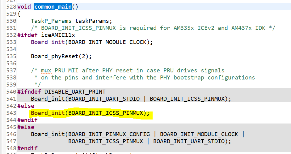
2, PRUSSPinMuxConfig(0x0); Input parameter is 0 or 1,What's the difference? There is no information to explain.

3,What are the direct reasons for this error waveform of RX_ER and RX_DV ? What are the possible causes ?

4, I didn't configure the enhanced link detection function.Is this the cause?


I made a detailed description including the schematic in last post of e2e.ti.com/.../792302

  • Hi Andy,

    1. U10 is the isolation switch to connect the two PHY1 signals that were isolated during power-up. PHY1 signals are connected to AMIC110 pins that operate as SYSBOOT inputs. Two of the PHY1 signals must be isolated from AMIC110 SYSBOOT inputs during power-on. The dual FET switch, U10, performs this task. The switch control inputs are connected to GPIO2_18 (pin L17) begins high-z with an internal pull-down after power is applied. The internal pull-down along with an external pull-down insures the switch is off as soon as power is applied.

    2. Not sure which SDK you were looking into. The 0x0 is likely the instance number of PRUSS. You may be able to find it out from the API source comment.

    3. Refer to e2e.ti.com/.../225297

    4. No, disabling enhanced link detection won't cause RX_ER.

    Regards,
    Garrett
  • Hi Garrett,
    The problem is not resolved.I never found out what caused it
    I thought either the dp83822 is misconfigured or the pru is misconfigured.I haven't found out what the problem is yet.
    PHY1 always periodically lose link.PHY9 works well.They are the same configuration except for the addresse.
    I made a detailed description including the schematic in last post of e2e.ti.com/.../792302
    I even suspect that EtherCAT firmware in AM335x is incompatible with DP83822.TLK110 will be discontinued.So we have no choice.
    I'm very confused.Please give me some guidance. Thanks a lot!

    Best Regards,
    Andy Zhou
  • Hi Garrett,

    Where can I find detailed instructions for these PRU_ICSS registers ?

    Best Regards,

    Andy Zhou

  • Andy,

    These PRU ICSS registers are defined in the PDK packages\ti\starterware\include\hw\soc_am335x.h, and you can find its descriptions in TRM section 4.5 - (PRU) registers.

    Regards,
    Garrett
  • Hi Garrett,

    I am glad to receive your reply!

    The problem remains unresolved.But I found the key point now.I said that periodic communication error is caused by RX_ER (PHY->PRU,PHY tell PRU that "I received error frame").
    Now I found the time point which the RX_ER started to send error signal.
    CSL_MDIO_init((((PRUICSS_HwAttrs *)(pruIcssHandle->hwAttrs))->prussMiiMdioRegBase), 200000000, 2200000u); After the statement is executed.
    You can find this statement in the EtherCAT demo program. It is before the PHY configuration program and PRU Enable.It means that the PHY is not configured and PRU not run.PHY1 is error, PHY9 is ok .Why?
    But this statement enable the MDIO and MDC to start working.So I doubt that the PRU change the PHY  register by MDIO and MDC.Can you tell what the PRU changes by this statement ?
    Or What the PRU read and write to the PHY ?I need to know these to analyze the problem.
    I guess this problem could  have something to do with enhanced link detection features.All of Ti EtherCAT designs used enhanced link detection.
    Have you actually verified that not use enhanced link detection especially for DP83822 and AM335x ? And our design is that the RXLINK pin is used as GPIO now .Is it possible that it has a bad effect on the PRU?
    I know AM3359 and TLK110 is used in ICEv2.But TLK110 will be halt production.We have no choice.We may unfortunately be the first to try this design. We've had this problem for almost a month.Our project is facing delay or termination.We need your full support.
    mdioParamsInit.enhancedlink_enable =TIESC_MDIO_RX_LINK_DISABLE;Is it enough to modify this one ?
    I have some questions about the MDIO configuration.
    1,CSL_MDIO_init((((PRUICSS_HwAttrs *)(pruIcssHandle->hwAttrs))->prussMiiMdioRegBase), 200000000, 2200000u); the statement does the following three things.
    Disable preamble , enable fault detection,active MDIO state machine.
    Why does it cause RX ER to output error ?
    2,"Link change status interrupts" What does it mean ?

    //Select PHY address enable link change interrupt at MDIOLinkIntMasked and MDIOLinkIntRaw
        if(pmdio_params->enhancedlink_enable == 0)
        {
            MDIO_enableLinkInterrupt((((PRUICSS_HwAttrs *)(
                                           pruIcssHandle->hwAttrs))->prussMiiMdioRegBase), 0, pmdio_params->addr0,
                                     MDIO_LINKSEL_DISABLE);
            MDIO_enableLinkInterrupt((((PRUICSS_HwAttrs *)(
                                           pruIcssHandle->hwAttrs))->prussMiiMdioRegBase), 1, pmdio_params->addr1,
                                     MDIO_LINKSEL_DISABLE);
        }
        else
        {
            MDIO_enableLinkInterrupt((((PRUICSS_HwAttrs *)(
                                           pruIcssHandle->hwAttrs))->prussMiiMdioRegBase), 0, pmdio_params->addr0,
                                     MDIO_LINKSEL_ENABLE);
            MDIO_enableLinkInterrupt((((PRUICSS_HwAttrs *)(
                                           pruIcssHandle->hwAttrs))->prussMiiMdioRegBase), 1, pmdio_params->addr1,
                                     MDIO_LINKSEL_ENABLE);
        }
    void MDIO_enableLinkInterrupt(uint32_t mdioBaseAddress, uint32_t phyInst,
                                  uint32_t phyNum, uint8_t linkSel)
    {
        uint32_t PhySel;
        PhySel = phyNum;
        PhySel |=  0x40;
        if(MDIO_LINKSEL_ENABLE == linkSel)
        {
            PhySel |= 0x80;
        }
        MDIO_userPhySel(mdioBaseAddress, phyInst, PhySel);
    }
    Looking forward to your reply!
    Best Regards,
    Andy Zhou
  • Andy,

    I should have replied you earlier if I were not out of office a few days last week.

    PRU module clock is enabled during Board_init() and MDIO module remains active before CSL_MDIO_init() which enables the MDIO state
    machine, uses standard pre-amble and sets the clock divider value. After MDIO module is initialized, the PHY registers can be accessed, and this can be confirmed by CSL_MDIO_phyRegRead() or CSL_MDIO_phyRegWrite() which always wait till transaction completion if any in the beginning. PHY register read, e.g Board_getPhyIdentifyStat() internally calls CSL_MDIO_phyRegRead().

    We did verify both enhanced link detection and MDIO state machine based link detection. However, we don't have the test case with DP83822 and AM335x.

    mdioParamsInit.enhancedlink_enable =TIESC_MDIO_RX_LINK_DISABLE is the only change needed for disabling enhanced link detection.
    Not sure if I forwarded the application note before - www.ti.com/.../spracc8.pdf, which has some details about the enhanced link detection description.

    Did you have the schematic reviewed by TI? If not, you may try to reach out to local TI team to request schematic review.

    Regard,
    Garrett
  • Hi Garrett,

    I know what you said.But you do not get the key point I said.

    "Now I found the time point which the RX_ER started to send error signal.

    CSL_MDIO_init((((PRUICSS_HwAttrs *)(pruIcssHandle->hwAttrs))->prussMiiMdioRegBase), 200000000, 2200000u); After the statement is executed.

    You can find this statement in the EtherCAT demo program. It is before the PHY configuration program and PRU Enable.It means that the PHY is not configured and PRU not run."

    I doubt very much that the PRU program in AM335x is not suitable for DP83822.

    What the PRU read and write to the PHY by MDIO ? I do not know. But it caused the RX error(I can see RX_D[0..3] is error by oscilloscope).

    I presume that the PRU write Incorrect configuration information to DP83822. It cause the reception of PHY is error.Because I've ruled out pretty much everything else.

    We hope we can get your expert's commitment that the PRU program in AM335x is OK for DP83822.

    By the way,the local TI team may not be able to review schematic. Because your expert don't have the test case with DP83822 and AM335x.

    The schematic was in my last post.Please ask your expert to review it.

    e2e.ti.com/.../792302

    Best Regards,

    Andy Zhou

  • Andy,

    The PRU program (firmware) for AM335x and AMIC110 are the same, see Readme.txt under PRU-ICSS-EtherCAT_Slave_01.00.07.02\protocols\ethercat_slave\firmware

    1) v1.0 -> ICSS v1.0 -> Present in AM335x, AMIC110 and AM572x PG1.x

    However if you just build the ethercat_slave_full_AM335x_arm CCS project and try to run it on your custom board, it may not work due to pinmux and PHY difference.

    - Have you updated the board library for the pinmux on your board?

    - which project (ethercat_slave_full_AM335x_arm or ethercat_slave_full_AMIC11x_arm) are you working with? If it's the latter (AMIC11x_arm), have you updated the GPIO pins in the board_phy.c to match with your schematic?

    Regarding the PRU (processor, not MDIO module) disable, see the bit description below. And the current PRU disable/enable flow works on AM335x/AMIC110 boards without issue. PRU firmware doesn't touch PHY. All the PHY configuration is done by ARM via MDIO of PRU-ICSS.

    Processor Enable: This bit controls whether or not the PRU is
    allowed to fetch new instructions.
    0 = PRU is disabled.
    1 = PRU is enabled.
    If this bit is de-asserted while the PRU is currently running and has
    completed the initial cycle of a multi-cycle instruction
    (LBxO,SBxO,SCAN, etc.), the current instruction will be allowed to
    complete before the PRU pauses execution.
    Otherwise, the PRU will halt immediately.
    Because of the unpredictability/timing sensitivity of the instruction
    execution loop, this bit is not a reliable indication of whether or not
    the PRU is currently running.
    The pru_state bit should be consulted for an absolute indication of
    the run state of the core.
    When the PRU is halted, its internal state remains coherent therefore
    this bit can be reasserted without issuing a software reset and the
    PRU will resume processing exactly where it left off in the instruction
    stream.

    Regards, Garrett

  • Hi Garrett,

    I changed the pin configuration when I create the project. So that's not the problem.PHY 9 always works well.

    1,Why did the RX_ERR of DP83822 start to make a error signal when "Enable the MDIO state machine"(CSL_MDIO_init()).I want to know why does the error signal  make at this time point.

    2,Why does the ICEv2 use U10 ?In other words, why did AMIC110 ICE use this isolation design but ICEv2 not?Because the periodic communication error occur in PHY1. PHY1 and AM3357 boot pins exist multiplex pins.

    But it does not affect the boot run of AM335x.

    This values is read from 0x467 and 0x468.You can konow the Hardware Bootstrap Configurations. The mode of RX_D2 is different because the address of PHY is different. It doesn't seem to affect the PHY bootstrap.

    By the way, did your expert review our schematic ?

    Best Regards,

    Andy Zhou

  • Andy,

    I have reached out our PHY expert for the RX_ERR issue.

    For schematic review, it typically takes a few weeks and have to go through a procedure with a complete schematic design.

    Regards, Garrett

  • Hi Garrett,

    Thanks a lot !  Looking forward to the expert's reply !

    I've been comparing the demo program between AMIC110 and AM335x.

    Why are pins repeatedly configured in the different program locations in AMIC110 ?I think that their configuration have the same effect.I am confused.

    I also found that Board_phyReset() is before the pin configuration in AMIC110 but the AM335x is just the opposite.

    I know these configuration has to do with this description in AMIC110 ICE user's guide.

    I am confused. If the isolation switch U10 prevents AMIC110 internal pull resistors from interfering with the bootstrapping of Ethernet PHY1,why didn't PHY2 have the same isolation design ?

    My understanding is that it just prevents PHY1 internal pull resistors from interfering with AMIC110  bootstrap. Is it right ?

    Best Regards,

    Andy

  • Andy,

    >>My understanding is that it just prevents PHY1 internal pull resistors from interfering with AMIC110 bootstrap. Is it right

    That's right - the AMIC110 pins connecting to PHY1 are LCD_DATA[x] whereas pins connecting to PHY2 are GPMC_A[x], and see AMIC110 data sheet section 4 - Terminal Configuration and Functions: (5) LCD_DATA[15:0] terminals are respectively SYSBOOT[15:0] inputs, latched on the rising edge of PWRONRSTn.

    Regards,
    Garrett
  • Hi Garrett,

    Is there any new reply from expert ?

    Regards,
    Andy Zhou
  • Andy,

    Let me try again tomorrow to see why we still haven't got any response.

    Regards,
    Garrett
  • Hi Garrett,

    We replaced DP83822 with TLK105 on my board.The pins (PFBOUT,PFBIN1,PFBIN2) are changed for Single Supply Operation in TLK105 (http://www.ti.com/lit/an/snla262/snla262.pdf) . Nothing has changed in the program.

    Now both PHY1 and PHY2 work well.This proves that our hardware design of the network and program are no problem. The combination of DP83822 and PRU0 of AM335x has problem and you never tested it.

    We just wanted a reason to justify why the combination of tlk105 and PRU0 is ok but the DP83822 not.

    The TLK105 is not recommended for the new designs.But the substitute product DP83822 may have problem.

    Best Regards,
    Andy Zhou

  • Andy,

    >>But the substitute product DP83822 may have problem.
    We don't have the AM335x + DP83822 experiment board, no quite sure how could cause the DP83822 failure. It might be some timing issue as Aniruddha explained in the thread e2e.ti.com/.../792302...
    As it appears the topic is now PHY/hardware specific, I would like to close the thread.

    Regards,
    Garrett
  • Hi Garrett,

    Please don't close this post yet. I will have a crucial test.
    I have applied for AMIC110. I am going to replace the AM335x with AMIC110 on my board. If the communication is ok, the problem should be caused by the difference between AM335x and AMIC110 in PRU.
    This is very helpful for engineers who encounter the same problem with AM335x.

    Best Regards,
    Andy Zhou,
  • Andy,

    Do you have any update on this? Is it still open?

    Thanks,
    Garrett
  • Hi Garrett,
    I am sorry that my leaders didn't allow me to spend any time on DP83822. I used the tlk105 instead of DP83822.
    Now the project is almost finished.
    I'm sorry I couldn't find what caused the problem.
    Please close this post.
    Thanks for your support!

    Best Regards,
    Andy