This thread has been locked.

If you have a related question, please click the "Ask a related question" button in the top right corner. The newly created question will be automatically linked to this question.

DM355 TV out clipping and flickering

Hi!

I'm having some troubles with the TV out of the DM355. I'm working on a custom board with the latest DVSDK.

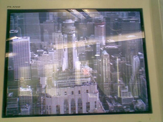
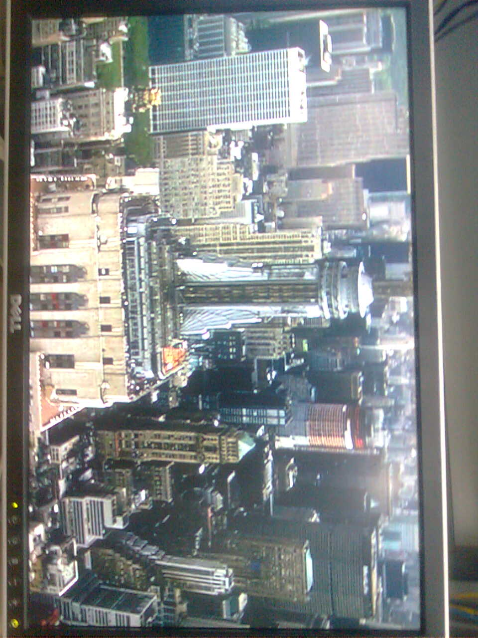
The problem is that the video output seems clipped on the left border as if the picture was displayed outside of the screen's border. I checked with different tvs and get varying results (some are clipping more, some are also clipping on the upper side, ...). I also have a lot of flicker in some portions of the picture, which leads me to think of a timing issue.


The problems are the same in 720x576x16 PAL and 720x480 NTSC.

I am only using the osd0 through the framebuffer.


Any help would be greatly appreciated!


Thanks alot,

Theodore

  • The flickering certainly sounds like a timing problem.  Are you seeing this on our DM355 EVM with the DVSDK software; if so, if you can tell us what you are doing so we can reproduce this on our side, it will help get to the bottom of this.  Otherwise, if you are using your own software or hardware, can you post a screenshot.

    With regards to the boarder clipping, most digital displays clip a few pixels on boarders to ensure you do not see artifacts, and how many pixels varies accross display manufacturers.  Not sure if this is what you are seeing, but if so, not sure if there is much you can do about it.  So long as you stick to the video standards for NTSC and PAL, you should see a decent image on most if not all displays.

  • Hi Juan,

    Thanks for your answer!

    The clipping is around 30 pixels, varying upon what I use to display the composite signal. I will try to test with the EVM ASAP to see if this may be hardware related. However the hardware design on the video out is almost copy&paste from the EVM schematics. The software itself is largely inspired by the demos from the dvsdk.

    There is also another problem I forgot to mention. Sometimes the screen goes black. And I have to restart the application in order to restore it. It sounds much like a software issue but I have no idea where this can be coming from.

    I guess I will also give a try to the evm demo softwares on our custom board to check if the problem is also happening.


    I'll get back to you as soon as I have completed those tests and will try to get you a picture of what is actually happening.

    Thanks,

    Theodore

  • Hi Juan!


    Here's two pictures showing the problem.

    This first picture has been taken from a laptop with a video acquisition card, the image is almost perfect though a little clipped on the left and on the upper side.

    Also please note on the upper left part of the image (topleft and third row), there is a small black rectangle which sometime appears when in NTSC mode (not in PAL).


    And this picture has been taken from a DLP. You can see there that the image is a lot more clipped on the left, upper and lower sides.

    I can't show any picture of the flickering (it's quite hard on a still image). It isn't visible with a plain still image like on the picture. However when I try to display tiny lines over it it shows up.

    And here is the output from fbset -i if that can be of any help:

    /opt # fbset -i

    mode "720x480-30"

            # D: 12.500 MHz, H: 14.863 kHz, V: 29.966 Hz

            geometry 720 480 720 960 16

            timings 80000 121 0 16 0 0 0

            accel false

            rgba 5/11,6/5,5/0,0/0

    endmode


    Any idea where this may come from? Or if there is any workaround I could use I we really need to have the whole picture displayed.


    Thanks alot for your help!

    Theodore

  • I am still a bit confused.  Are both the images above coming out from DM355 video output port and are being displayed in different display devices (e.g. PC via cpature card, and DLP).  If the DM355 running the same mode, and outputting the same video... the difference in the pics would have to be accounted for the difference in the display devices. 

    From a DM355 perspective, the output video port is very flexible; I suspect you are using the digital output interface... if so, you have a great deal of control over the timing of the video frame and choice of output pixel clock you can use.  From a display perspective, displays tend to very slightly from manufacturer to manufacturer; some perform really great at 29.996 HZ, others better at 30 HZ, and other have other slight variations.  You will still see a picture in all of them, but depending on what the display is capable of, you may see more clipping, flickering effects.  For this reason, the industry has promoted use of BT.656 starndards to help reduce the variability among implementations of NTSC standards.  DM355 also supports BT.656, but it also gives you flexible control of video timing parameters when not in BT.656 mode.

  • Hi Juan,


    Yes, the images comes from the same DM355 configured the same way and running the same software. Actually I took the first picture then unplugged the composite video cable from the acquisition card and plugged it in the DLP without changing anything on the board.


    I am pretty sure the DLP itself has troubles displaying correctly the PAL signal, it is just *too much* different to be only the DM355's fault. I also tried with an LCD screen which has a PAL input. The image was way better than with the DLP, but still clipped on the upper and left sides.

    I guess I'm going to try tweaking the timings to see if I can get anything better. Which files should I dig into?


    Also, from time to time (every 5/10 minutes) the video output goes black. If I restart the software (not the whole board) it works properly for another few minutes. I have no idea what can be causing this. I believe it is not software related as it also happens with the linux boot logo. Any idea?


    Anyways thanks alot for your help Juan!

    Theo

  • Hi Theo/Juan,

    Even I am facing same kind of problem in DM365 EVM with dvsdk v2.10..

    I am trying to display an image of 720x480 resolution (NTSC) on an anloag TV, using OSD0. I have set the bootargs as video=davincifb:vid0=1280x720x16,5400K:vid1=1280x720x16,5400K:osd0=1280x720x16,5400K


    But the displayed image has been cropped in all the four directions by around 30 pixels. I tried the same by using VID1, but there is no difference in the result.

    When I tried with different resolution (say 720x576) the amount of cropping is different in all four directions.

    I am not sure why this is happening? Can you please help me to resolve this issue.

    Whether I need to modify any timing parameters like V-Sync and H-Sync?


    Regards

    Jai


  • If you just want NTSC or PAL, why do you allocate 720P buffers?

    By cropped, do you mean you don't see the edges? or you see VID0 instead of OSD0 at the boarder? Could this clipping be cused by overscan of your TV? Maybe you should try a TV with underscan feature?

  • Hi Paul,

    My actual requirment is to display NTSC, PAL, 720P and 1080i resolutions.

    Cropping means, I am not able to see the edges by around 30-35 pixels in all four directions. For this I am using either OSD0 or VID0, so I am sure there can't be any overlapping between these two.

    I tried this with different scan/resolution TVs But all of them display the same (Cropped one).

    You have any idea on this??


    Regards

    Jai


  • Is this analog output?

    What do you mean by "so I am sure there can't be any overlapping between these two?" You should first find out whether it is the entire video being cropped, or only the OSD0. On the other hand, see if the VID0 is visible in the cropped region. If not, whether the video background is visible.

    Without getting more information, I think this is still a TV related problem. Do you have a professional monitor?

    If possible, you should write a CCS testcase; it is easier to debug.

  • Hi Jai,

    As Paul mentioned, it seems to be a problem with the TV still. All CRT TVs have a degree of hidden pixels. The CRTs would not display all the data.

    Have you tried any LCD panel that takes in analog input and display?

    How are you so sure that the data is cropped by display side? Did you check the YUV data that goes into VID0 and does it look more than what you see on your TV? I am asking this question because i want to ensure that it is not the capture that is doing any sort of cropping based on your configuration.

    Once you try LCD TVs or profession monitors as Paul mentioned and still the problem exist, then we would need the register dumps and a possible CCS test case to recreate the issue.


    Regards,

    Anshuman

  • Hi,

    Yes. I am testing the analog output of DM365 EVM. I have tried with even professional LCD monitors.

    Since I am using only OSD0, I think there can't be any overlap between OSD0 and VID0.

    I agree that all CRT TVs have a degree of hidden pixels, but it will not be as much as 30-40 pixels.

    I confirmed the cropping of the image as follows,
    I took a 720x480 YUV 4:2:2 image, and displayed on the monitor using OSD0. But I am not getting the entire image on the display.

    I am using DVSDK v2.10. Please let me know how I can dump the registers so that I can post it for your reference.


    Thanks

    Jai


  • Jai,

    Attached are read and write utilities that you can use to read and write the registers. Please dump the OSD and VENC registers of VPBE. Looks like there can be possible configuration problem for startX, startY and the size registers.

    Also, if possible share with us your original image (YUV) and what you are seeing on the display, along with the registers.

    Regards,

    Anshuman

  • Jai,

    Sorry, missed the attachment in last post. Attaching "read_write.zipx" in this post. Rename it to .zip and unzip. Place these files in your target filesystem and use them to read or write the registers.

    Regards,

    Anshuman

    read_write.zipx
  • Jai,

    Could you do further experiments on the register read write?

    Regards,

    Anshuman

  • Dear Anshuman,

    Thanks for the replay..

    I am attaching the register dump of OSD and VENC.

    ------------------------------------------
    OSD --- ./readl 0x01c71c00 0 80
    ------------------------------------------
    00000  00000000 00000000 0000203B 00008002
    00010  00000000 00000000 00000000 00000000
    00020  0000102D 0000100C 00000000 00000000
    00030  00000000 00000304 00005460 00008000
    00040  00000079 00000010 00000000 00000000
    00050  00000000 00000000 00000000 00000000
    00060  00000000 00000000 00000000 00000000
    00070  000002D0 000000F0 00000000 00000000
    00080  000002D0 000000F0 00000000 00000000
    00090  00000000 00000000 00000000 00000000
    000A0  00000000 00000000 00000000 00000000
    000B0  00000000 00000000 00000000 00000000
    000C0  00000000 00000000 00000000 00000000
    000D0  00000000 00000000 00000000 00000000
    000E0  00000000 00000000 00000000 00000000
    000F0  00000000 00000000 00000000 00000000
    00100  00000000 00000000 00000000 00000000
    00110  00000000 00000000 00000000 00000000
    00120  00000000 00000000 00000000 00000000
    00130  00000000 00000000 00000000 00000000
    00140  00000000 00000000 00000000 00000000
    00150  00000000 00000000 00000000 00000000
    00160  00000000 00000000 00000000 00000000
    00170  00000000 00000000 00000000 00000000
    00180  00000000 00000000 00000000 00000000
    00190  00000000 00000000 00000000 00000000
    001A0  00000000 00000000 00000000 00000000
    001B0  00000000 00000000 00000000 00000000
    001C0  00000000 00000000 00000000 00000000
    001D0  00000000 00000000 00000000 00000000
    001E0  00000000 00000000 00000000 00000000
    001F0  00000000 00000000 00000000 00000000

    ------------------------------------------
    VENC --- ./readl 0x01c71e00 0 80
    ------------------------------------------
    00000  00000003 00000000 00000000 00000000
    00010  00000000 00000000 00000000 00000000
    00020  00000000 00000000 00000000 00000000
    00030  00000000 00000000 00000000 00000000
    00040  0000FF00 00000000 00000000 00000000
    00050  00000000 00000000 00000000 00000000
    00060  00000000 00000000 00000000 00000000
    00070  00000000 00000000 00000000 00000000
    00080  00000000 00000000 00000000 00000000
    00090  00000000 00000000 00000000 00000000
    000A0  00000000 00000000 00000000 00000000
    000B0  00000000 00000000 00000010 00000000
    000C0  00000000 00000000 00000000 0000017A
    000D0  00000000 00000000 00000000 00000000
    000E0  00000100 00000000 00000000 00000000
    000F0  00000000 00000000 00000000 00000000
    00100  00000400 0000057C 00000159 000002CB
    00110  000006EE 00000400 0000057C 00000159
    00120  000002CB 000006EE 00000000 00000001
    00130  00000002 00000000 00000000 00000000
    00140  00000001 00000000 00000000 00000000
    00150  00000000 00000000 00000000 00000000
    00160  00000000 00000000 00000000 00000000
    00170  0000D642 00000000 00000000 00000000
    00180  00000000 00000000 00000000 00000000
    00190  00000000 00000000 00000000 00000000
    001A0  00000000 00000000 00000000 00000000
    001B0  00000000 00000000 00000000 00000000
    001C0  00000000 00000000 00000000 00000000
    001D0  00000000 00000000 00000000 00000000
    001E0  00000000 00000000 00000087 0000FFE7
    001F0  00000008 00000000 00000000 00000000

    Following are the original image (720x480) and snapshot of the display on analog TV as well as LCD dispaly.

    INPUT IMAGE:                                                


    DISPALY ON ANALOG TV


    DISPLAY ON LCD MONITOR


    You can see that the LCD monitor is displaying more than Analog TV, but still not perfect.

    Please let me know, is there any wrong with register setting...


    Regards

    Jai


  • This is the code I am using to display the image.

    1616.fbdev_loopback.zip

  • Hi Jai,

    Looking at your registers, everything looks good. I need one more register which is VPSS_CLK_CTRL (address 0x1c40044). In this register VPSS_CLKMD should be 0 instead of 1.

    Also, i can suggest one more option. Can you try the color bar that video encoder outputs? That does not really need lot of register setting other than VDPRO register of VENC module. The OSD settings are not valid when color bar is used.

    Meanwhile, i will check more internally if somebody has seen similar issues.

    Regards,

    Anshuman

  • Jai,

    Although your BASEPX and BASEPY register look good, can you try changing BASEPX and BASEPY one by one to see if it starts showing up the complete data on your TV.

    When you connected LCD monitor, are you using VGA output or still analog NTSC output?

    Regards,

    Anshuman

  • Hi Anshuman,

    The value of VPSS_CLK_CTRL (address 0x1c40044) is coming 0x00000018. This means VPSS_CLKMD is 0.

    Even I tried with changing BASEPX and BASEPY registers one by one. This results in shifting the display either vertically or horizontally. When I tried to make the left side of the display proper, it cropped more pixels on right side...

    When I connected LCD monitor, I am still using analog NTSC output.


    Apart from this I have two more doubts.
    1. When I tried to display PAL (720x576), I am able to do so only with composite output. When I configured to component ouput for PAL, its giving error like "Failed FBIOPUT_VSCREENINFO". That means davinci won't support component output for PAL??
    (All other resolutions are working with component output)

    2. I even want to display 960P (960x1080) resolution. This resolution is same as 1080P (1920x1080) but alternate horrizontal pixels need to be displayed. Some of the timing parameters for this resolutions are

    FRAME_START             = Line    1
    ACTIVE_VIDEO_START      = Line   42
    VERTICAL_BLANKING_START = Line 1122
    FRAME_END               = Line 1125

    LINE_START (also ACTIVE_VIDEO_START) = Pixel    0
    HORIZONTAL_BLANKING_START            = Pixel  960
    LINE_END                             = Pixel 1099

    How to set these timing parameters? Is it through fb_var_screeninfo structure or need to write directly on registers.

    If I need to set these through fb_var_screeninfo, then how to calculate 'pixclock' ? In other way, if I need to set the registers directly, is there any API available for this??

    Please guide me..

    Regards
    Jai

  • Hi Anshuman,

    Regarding my 960P (960x1080) query, I understood that the timing parameters need to be set fb_var_screeninfo structure. Also I found out the way to calculate pixclock.

    But I coun'd able to find any information regarding,

    1. How to calculate hsync_len and vsync_len parameters in fb_var_screeninfo structure.

    2. How to divide the clock, so that I can output alternate horizontal pixels to achives 960P.

    Please let me know regarding thses...

    Regards

    Jai

  • Hi Anshuman,

    I am stiil facing the problem. Plaease let me know, if u have any updates..


    Jai

  • Hello I am working on the Tv out functionality, but I am not able to fins any Tvout cable for the zoom3 board. Does it come form with the board. 

    Please help me in this regard.