This thread has been locked.

If you have a related question, please click the "Ask a related question" button in the top right corner. The newly created question will be automatically linked to this question.

RTOS/PROCESSOR-SDK-AM437X: How to create a proper configuration with PinMUX

Part Number: PROCESSOR-SDK-AM437X
Other Parts Discussed in Thread: AM3359, AM3357, AM4377, AM4379, TPS65218

Tool/software: TI-RTOS

Hello TI team!

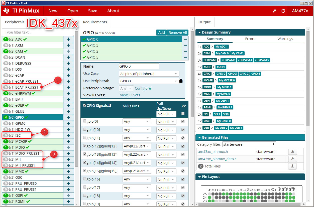
I have a custom board which similar to EVM_AM437x but some pins are rerouted and some functionality is removed to make it smaller (nothing is added). And I have to run EtherCAT slave on my custom board (I'm using EtherCAT slave example for IDK_AM437x). 

So I decided to take existing pinmux configs for the IDK_AM437x and EVM_AM437x boards and to create my own made-to-measure configuration. But I lack some understanding of how to correctly configure pins. Here we go:

Now questions related to IDK_AM437x:

I'm running EtherCAT slave on the IDK_AM437x board and it is working just fine. So I assume the configuration is correct. 

  1. Why EtherCAT is not enabled on the PRU but it actually works?
  2. Why I2C is not enabled at all but it actually works (I can read board ID from the EEPROM through I2C)
  3. Why no network card is defined in general? 

  4. GPIO groups GPIO1 and GPIO4 are not mapped, but EtherCAT slave actually triggers AD23 pin which is located on GPIO4 and it works! Why?
 

    /*PRUETH0_RESETn */
    PhyResetInfo[0].pin = 20;
    PhyResetInfo[0].baseAddr = SOC_GPIO4_REG;

Why does it work?

Now questions related to EVM_AM437x:

  1. Why EtherCAT is not described although the board listed as theoretically supporting EtherCAT (for unknown reasons there is no sample/demo project for EVM board!!!)
  2. Why I2C is defined here? It is different from IDK_AM437x
  3. Why no network cards are described?
  4. Why no PRU is described/defined? How it works in that case?

On my custom board pins T20, T21 and T22 are used to reset the NICs (not AD23 as for IDK_AM437x board OR Y23(?) for the EVM_437x board). But they are not working and it looks like the reason is because these pins are described as RX (read-only). Am I correct?

And the final very important question about EtherCAT slave demo (binary libs):

It is designed to work on IDK_AM437x (AM4379 CPU) - ethercat_slave_demo_AM437x_arm

Will it work on the board with AM4377 CPU? Theoretically these are the different processors and instructions can be different?

Documentation from the EtherCAT stack says it is possible: "PRU-ICSS EtherCAT firmware implements EtherCAT slave controller layer2 functionality and provides EtherCAT ASIC like functionality integrated into AM3357/AM3359/AM4377/AM4379 SOC with PRU-ICSS IP." But it is not clear if it is related to the source distribution only or to the binary also.

Any help will be very appreciated!!!

  • Hi Oleg,

    Let me answer your questions about EtherCAT on IDK_AM437x first.

    >>Why EtherCAT is not enabled on the PRU but it actually works?

    Ans: PRU firmware (protocols\ethercat_slave\firmware\v2.0) is loaded from ARM, see bsp_init().

    >>Why I2C is not enabled at all but it actually works (I can read board ID from the EEPROM through I2C)

    Ans: I2C EEPROM is not a necessary part for EtherCAT slave.

    >>Why no network card is defined in general?  

    Ans: Not quite sure your question - what do you mean network card? The EtherCAT frames are processed by PRU.

    >> GPIO groups GPIO1 and GPIO4 are not mapped, but EtherCAT slave actually triggers AD23 pin which is located on GPIO4 and it works! Why?

    Ans: I will dig into this and then get back to you. I guess the GPIO4/pin20 is probably for other IDK boards, and if it's not mapped on AM437x IDK, it's a not-care.

    Regards,

    Garrett

  • Hi Oleg,

    Regarding the AD23 pin, its 'BALL RESET REL. MODE' is 7 - GPIO, gpio4_20, see your snapshot above or AM4379 datasheet Table 4-10 Pin Attributes, and the GPIO 4 clock is enabled in the function Board_phyManualReset():
    GPIOModuleEnable(PhyResetInfo[0].baseAddr);
    BALL RSET REL. MODE is 'automatically configured after the active low PWRONRSTn terminal transitions from low to high'.
    So it works though it's labeled as CAM1_DATA6.

    To the questions related to EVM_437x:
    1. The EVM_437x is targeted to 'enable developers to evaluate secure boot functionality including signing and encryption on high secure AM437x devices', and IDK_437x is intended to 'evaluate the industrial communication and control capabilities of Sitara™ AM4379 and AM4377 processors for industrial applications.'

    2. The I2C0 on AM437x EVM is used to control the Smart Reflex port and control port on the TPS65218
    3. why are network cards needed?
    4. PRU firmware is still loaded through ARM. You can refer to ICSS_EMAC test example from Processor SDK.

    If you configure any of T20, T21 or T22 as GPIO pin, and then enable its clock module and direction (OUTPUT) as below, it should work.
    GPIOModuleEnable(PhyResetInfo[0].baseAddr);
    GPIODirModeSet(PhyResetInfo[0].baseAddr, PhyResetInfo[0].pin, GPIO_DIR_OUTPUT);

    The major difference between AM4377 and AM4379 is 3D graphic support, and you can see the comparison here - www.ti.com/.../AM4377

    ethercat_slave_demo_AM437x_arm will work with AM4377 if the only difference is the processor AM4377 vs. AM4379.

    Regards,
    Garrett
  • Thank you for the clarification, Garrett!