This thread has been locked.

If you have a related question, please click the "Ask a related question" button in the top right corner. The newly created question will be automatically linked to this question.

Linux/AM5718: QSPI configuration in U-boot

Part Number: AM5718

Tool/software: Linux

Hi

We have a custom board with the AM5718 and doing the board bring up.

We using the latest u-boot, private .dts and dtsi files (based on the am571x-idk and am571x-evm files.

our schematic look like this

our .dtsi file look like this (no qspi references are in our .dts file), it is essential a modified copy from am57xx-idk-common.dtsi

&qspi {
 status = "okay";
 spi-max-frequency = <76800000>;
 m25p80@0 {
  compatible = "s25fl512s", "jedec,spi-nor";
  spi-max-frequency = <76800000>;
  reg = <0>;
  spi-tx-bus-width = <4>;
  spi-rx-bus-width = <4>;
  #address-cells = <1>;
  #size-cells = <1>;
  cdns,tshsl-ns = <392>;
  cdns,tsd2d-ns = <392>;
  cdns,tchsh-ns = <100>;
  cdns,tslch-ns = <100>;
  /* MTD partition table.
   * The ROM checks the first four physical blocks
   * for a valid file to boot and the flash here is
   * 64KiB block size.
   */
  partition@0 {
   label = "QSPI.SPL";
   reg = <0x00000000 0x000040000>;
  };
  partition@1 {
   label = "QSPI.u-boot";
   reg = <0x00040000 0x00100000>;
  };
  partition@2 {
   label = "QSPI.u-boot-spl-os";
   reg = <0x00140000 0x00080000>;
  };
  partition@3 {
   label = "QSPI.u-boot-env";
   reg = <0x001c0000 0x00010000>;
  };
  partition@4 {
   label = "QSPI.u-boot-env.backup1";
   reg = <0x001d0000 0x0010000>;
  };
  partition@5 {
   label = "QSPI.kernel";
   reg = <0x001e0000 0x0800000>;
  };
  partition@6 {
   label = "QSPI.file-system";
   reg = <0x009e0000 0x01620000>;
  };
 };
};


We have updated our own mux file based on the output from the pinmuxtool

{GPMC_A13, (M1 | PIN_INPUT | MANUAL_MODE)},	/* R3 gpmc_a13.qspi1_rtclk */
{GPMC_A14, (M1 | PIN_INPUT | MANUAL_MODE)},	/* T2 gpmc_a14.qspi1_d3 */
{GPMC_A15, (M1 | PIN_INPUT | MANUAL_MODE)},	/* U2 gpmc_a15.qspi1_d2 */
{GPMC_A16, (M1 | PIN_INPUT | MANUAL_MODE)},	/* U1 gpmc_a16.qspi1_d0 */
{GPMC_A17, (M1 | PIN_INPUT | MANUAL_MODE)},	/* P3 gpmc_a17.qspi1_d1 */
{GPMC_A18, (M1 | PIN_OUTPUT | MANUAL_MODE)},	/* R2 gpmc_a18.qspi1_sclk */
.
.
.
.
{GPMC_CS2, (M1 | PIN_OUTPUT | MANUAL_MODE)},	/* P2 gpmc_cs2.qspi1_cs0 */


The output from the u-boot prompt on "sf probe" is 

=> sf probe
unrecognized JEDEC id bytes: 00, 00, 00
Failed to initialize SPI flash at 0:0 (error -2)

Do anyone have any ideas why ?

Do we need to add something in arch/arm/dts/dra72x-mmc-iodelay.dtsi ?

Should spi-tx-bus-width be
  spi-tx-bus-width = <1>;
or
  spi-tx-bus-width = <4>;

Should it be s25fl256s1 or s25fl256s1_512 ?

Do we need the cdns,ts parameters ?

Regards

  • You're missing pullups on D2 and D3. Best solution is to add them on your board, but for now enabling the internal pullup in u-boot mux_data.h should be sufficient.
  • We tried to add the pull up but no difference,

    If we switch on all debug message we get the following output

    => sf probe 0
    uclass_find_device_by_seq: 0 0
       - 0 -1 'qspi@4b300000'
       - not found
    spi_find_bus_and_cs: No bus 0
    uclass_find_device_by_seq: 0 0
       - 0 -1 'qspi@4b300000'
       - not found
    uclass_find_device_by_seq: 1 0
       - 0 -1 'qspi@4b300000'
       - found
    uclass_find_device_by_seq: 0 0
       - 0 -1 'qspi@4b300000'
       - not found
    ofnode_read_u32: syscon-chipselects: 0x7 (7)
    OF: ** translation for device qspi@4b300000 **
    OF: bus is default (na=1, ns=1) on ocp
    OF: parent bus is default (na=2, ns=2) on
    OF: walking ranges...
    OF: default map, cp=0, s=c0000000, da=4b300000
    OF: with offset: 1261436928
    OF: reached root node
    fdtdec_get_addr_size_auto_noparent: fdtdec_get_addr_size_auto_parent: na=1, ns=1, fdtdec_get_addr_size_fixed: reg: addr=5c000000, size=4000000
    OF: ** translation for device qspi@4b300000 **
    OF: bus is default (na=1, ns=1) on ocp
    OF: parent bus is default (na=2, ns=2) on
    OF: walking ranges...
    OF: default map, cp=0, s=c0000000, da=5c000000
    OF: with offset: 1543503872
    OF: reached root node
    fdtdec_get_int: spi-max-frequency: 0x493e000 (76800000)
    fdtdec_get_int: num-cs: 0x4 (4)
    ti_qspi_ofdata_to_platdata: regs=<0x4b300000>, max-frequency=76800000
    ofnode_read_u32: spi-max-frequency: 0x493e000 (76800000)
    spi_find_chip_select: plat=fcf35110, cs=0
    uclass_find_device_by_seq: 0 -1
    uclass_find_device_by_seq: 0 0
       - -1 -1 'm25p80@0'
       - not found
    spi_flash_std_probe: slave=fcf3c188, cs=0
    ti_spi_set_speed: hz: 76800000, clock divider 0
    tx cmd 003a0fff dc 00000000
    tx done, status 00010002
    rx cmd 00390fff dc 00000000
    rx done, status 00020002, read 01
    rx cmd 00390fff dc 00000000
    rx done, status 00030002, read 02
    rx cmd 00390fff dc 00000000
    rx done, status 00040002, read 20
    rx cmd 00390fff dc 00000000
    rx done, status 00050002, read 4d
    rx cmd 00390fff dc 00000000
    rx done, status 00060002, read 00
    rx cmd 00390fff dc 00000000
    rx done, status 00070002, read 80
    9f | [6B in] 01 02 20 4d 00 80 [ret 0]
    tx cmd 003a0fff dc 00000000
    tx done, status 00010002
    rx cmd 00390fff dc 00000000
    rx done, status 00020002, read 31
    35 | [1B in] 31 [ret 0]
    tx cmd 003a0fff dc 00000000
    tx done, status 00010002
    rx cmd 00390fff dc 00000000
    rx done, status 00020002, read ff
    05 | [1B in] ff [ret 0]
    tx cmd 003a0fff dc 00000000
    tx done, status 00010002
    06 | [0B -] [ret 0]
    tx cmd 003a0fff dc 00000000
    tx done, status 00010002
    tx cmd 003a0fff dc 00000000
    tx done, status 00020002
    tx cmd 003a0fff dc 00000000
    tx done, status 00030002
    01 | [2B out] ff 33 [ret 0]
    tx cmd 003a0fff dc 00000000
    tx done, status 00010002
    rx cmd 00390fff dc 00000000
    rx done, status 00020002, read ff
    05 | [1B in] ff [ret 0]
    tx cmd 003a0fff dc 00000000
    tx done, status 00010002
    30 | [0B -] [ret 0]
    spi_get_bus_and_cs: Error path, created=0, device 'm25p80@0'
    Failed to initialize SPI flash at 0:0 (error -5)
    Command failed, result=1


  • I don't see the error about unrecognized jedec bytes. I think the pullups resolved that issue.

    The tx-width should be 1. Which SDK version are you using?
  • Our -dtsi file, inspired by another file that use the s25fl512s looks like this now

    Compile that is used is 

    export CROSS_COMPILE=arm-linux-gnueabihf-
    export ARCH=arm
    export PATH=$HOME/gcc-linaro-4.9-2015.05-x86_64_arm-linux-gnueabihf/bin:$PATH

    qspi {
    	status = "okay";
    
    	m25p80@0 {
    		compatible = "spansion, s25fl512s", "jedec,spi-nor";
    		spi-max-frequency = <30000000>;
    		reg = <0>;
    		spi-tx-bus-width = <1>;
    		spi-rx-bus-width = <4>;
    		#address-cells = <1>;
    		#size-cells = <1>;
    		spi-cpha;
    		spi-cpol;
    		m25p,fast-read;

    The output look like this now

    => sf probe 1
    uclass_find_device_by_seq: 0 0
       - 0 -1 'qspi@4b300000'
       - not found
    spi_find_bus_and_cs: No bus 0
    uclass_find_device_by_seq: 0 0
       - 0 -1 'qspi@4b300000'
       - not found
    uclass_find_device_by_seq: 1 0
       - 0 -1 'qspi@4b300000'
       - found
    uclass_find_device_by_seq: 0 0
       - 0 -1 'qspi@4b300000'
       - not found
    ofnode_read_u32: syscon-chipselects: 0x7 (7)
    OF: ** translation for device qspi@4b300000 **
    OF: bus is default (na=1, ns=1) on ocp
    OF: parent bus is default (na=2, ns=2) on
    OF: walking ranges...
    OF: default map, cp=0, s=c0000000, da=4b300000
    OF: with offset: 1261436928
    OF: reached root node
    fdtdec_get_addr_size_auto_noparent: fdtdec_get_addr_size_auto_parent: na=1, ns=1, fdtdec_get_addr_size_fixed: reg: addr=5c000000, size=4000000
    OF: ** translation for device qspi@4b300000 **
    OF: bus is default (na=1, ns=1) on ocp
    OF: parent bus is default (na=2, ns=2) on
    OF: walking ranges...
    OF: default map, cp=0, s=c0000000, da=5c000000
    OF: with offset: 1543503872
    OF: reached root node
    fdtdec_get_int: spi-max-frequency: (not found)
    fdtdec_get_int: num-cs: 0x4 (4)
    ti_qspi_ofdata_to_platdata: regs=<0x4b300000>, max-frequency=-1
    ofnode_read_u32: spi-max-frequency: (not found)
    spi_find_chip_select: plat=fcf35110, cs=0
    spi_get_bus_and_cs: Binding new device 'spi_flash@0:1', busnum=0, cs=1, driver=spi_flash_std
    uclass_find_device_by_seq: 0 -1
    uclass_find_device_by_seq: 0 0
       - -1 -1 'm25p80@0'
       - -1 -1 'spi_flash@0:1'
       - not found
    spi_flash_std_probe: slave=fcf3bfb0, cs=1
    ti_spi_set_speed: hz: 1000000, clock divider 76
    tx cmd 103a0fff dc 00050000
    tx done, status 00010002
    rx cmd 10390fff dc 00050000
    rx done, status 00020002, read 01
    rx cmd 10390fff dc 00050000
    rx done, status 00030002, read 02
    rx cmd 10390fff dc 00050000
    rx done, status 00040002, read 20
    rx cmd 10390fff dc 00050000
    rx done, status 00050002, read 4d
    rx cmd 10390fff dc 00050000
    rx done, status 00060002, read 00
    rx cmd 10390fff dc 00050000
    rx done, status 00070002, read 80
    9f | [6B in] 01 02 20 4d 00 80 [ret 0]
    SF: Detected s25fl512s_256k with page size 256 Bytes, erase size 256 KiB, total 64 MiB
    ti_spi_set_speed: hz: 1000000, clock divider 76
    spi_get_bus_and_cs: bus=fcf35040, slave=fcf3bfb0
    

    It seems that it works (SF: Detected s25fl512s_256k with page size 256 Bytes, erase size 256 KiB, total 64 MiB)

    Let me investigate it further before we close this thread, thanks a lot for helping us in the right direction.

    The key modifications seems to be 

    &qspi {
    	status = "okay";
    
    	m25p80@0 {
    		compatible = "spansion, s25fl512s", "jedec,spi-nor";
    		spi-max-frequency = <50000000>;
    		reg = <0>;
    		spi-tx-bus-width = <1>;
    		spi-rx-bus-width = <4>;
    		#address-cells = <1>;
    		#size-cells = <1>;
    		spi-cpha;
    		spi-cpol;
    		m25p,fast-read;

  • I have digged further and added more debug prints
    It fails at the end of function write_sr_cr in spi_nor_core.c

    tx cmd 003a0fff dc 00000000
    tx done, status 00010002
    06 | [0B -] [ret 0]
    tx cmd 003a0fff dc 00000000
    tx done, status 00010002
    tx cmd 003a0fff dc 00000000
    tx done, status 00020002
    tx cmd 003a0fff dc 00000000
    tx done, status 00030002
    01 | [2B out] ff 33 [ret 0]
    tx cmd 003a0fff dc 00000000
    tx done, status 00010002
    rx cmd 00390fff dc 00000000
    rx done, status 00020002, read ff
    05 | [1B in] ff [ret 0]
    tx cmd 003a0fff dc 00000000
    tx done, status 00010002
    30 | [0B -] [ret 0]
    write_sr_cr Timeout while writing configuration register
    spansion_read_cr_quad_enable 4
    spi_nor_init 4 quad mode not supported


    Any hints of what might be wrong ?


    Our flash is
    www.cypress.com/.../download

    &qspi {
    status = "okay";

    flash0: m25p80@0 {
    compatible = "spansion,s25fl512s","jedec,spi-nor";
    reg = <0>;
    spi-tx-bus-width = <1>;
    spi-rx-bus-width = <4>;
    spi-max-frequency = <96000000>;
    #address-cells = <1>;
    #size-cells = <1>;
    cdns,tshsl-ns = <392>;
    cdns,tsd2d-ns = <392>;
    cdns,tchsh-ns = <100>;
    cdns,tslch-ns = <100>;
    block-size = <18>;
  • Stefan Thorlacius said:
    &qspi { status = "okay"; m25p80@0 { compatible = "spansion, s25fl512s", "jedec,spi-nor"; spi-max-frequency = <50000000>; reg = <0>; spi-tx-bus-width = <1>; spi-rx-bus-width = <4>; #address-cells = <1>; #size-cells = <1>; spi-cpha; spi-cpol; m25p,fast-read;

    I want to make sure you're aware of a very close relationship between the items I highlighted above and the pin muxing.  For example, here's a snippet out of the data manual:

    So as you can see, the max speed differs depending on whether you're using Mode 0 or Mode 3.  This also ties into the pin muxing, as there are different I/O modes depending on whether you're using Mode 0 or Mode 3:

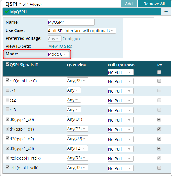
    This is why the PinMux Tool needs you to specify whether you plan to use Mode 0 or Mode 3:

    You should only add spi-cpha and spi-cpol if you're using Mode 3.  If that's the case however, you must set your maximum frequency to 48 MHz and be sure that the pin muxing is configured correctly (i.e. you may need to regenerate your pin muxing and rerun the perl script).

    Best regards,
    Brad

  • Stefan Thorlacius said:
    cdns,tshsl-ns = <392>;
    cdns,tsd2d-ns = <392>;
    cdns,tchsh-ns = <100>;
    cdns,tslch-ns = <100>;

    These are not valid options for AM57xx.  The device tree for AM57xx QSPI binds to "ti,dra7xxx-qspi" which relates to the driver in drivers/spi/ti_qspi.c.  There are other TI devices like K2G and AM65xx that leverage the Cadence IP and underlying driver.  You should remove the cdns references for your AM57xx based design.

  • Thanks brad for all your help

    After applying your suggestions and tried it on Another custom board we got it working.

    It still do not work on originally board that I used, we consider my board as broken and further investigation will be needed to check the hardware.

    This thread can be closed

    Regards