Part Number: AM5718
Hello,
I have a couple of questions regarding the Technical Reference Manual of the AM571x device, chapter 27 General-Purpose Interface.
#1 27.4.2.1 Synchronous Path: Interrupt Request Generation
In this chapter you can read the following sentence:
The general-purpose interface has 14 interrupt lines (two interrupt lines per GPIO module instance for biprocessor operation for GPIO1 through GPIO6 and one interrupt line for GPIO7 and GPIO8 module instance). The 16 interrupt signals are GPIOi_IRQ_1 (used by the MPU, DSP and IPU subsystems) and GPIOi_IRQ_2 (used by the CROSSBAR), where i = 1 to 8.
I do not undestand why this paragraph talks about 14 interrupt lines, but there is no other text or figure within this chapter sustaining this statement. For example, at the top of page 6922, you can read the following:
The general-purpose interface has 16 interrupt lines (two interrupt lines on GPIO1 through GPIO8 modules).
I have also checked the AM572x TRM file, no changes. I would like you to explain me where the "14 lines" come from.
#2 Mapping of interrupt signals
Each GPIOx module (where x = 1 to 8) has two interrupt lines: GPIOx_IRQ_1 and GPIOx_IRQ_2. From the above paragraph, GPIOx_IRQ_1 is mapped to cores (used by the MPU, DSP and IPU subsystems) and GPIOx_IRQ_2 is mapped to IRQ_CROSSBAR.
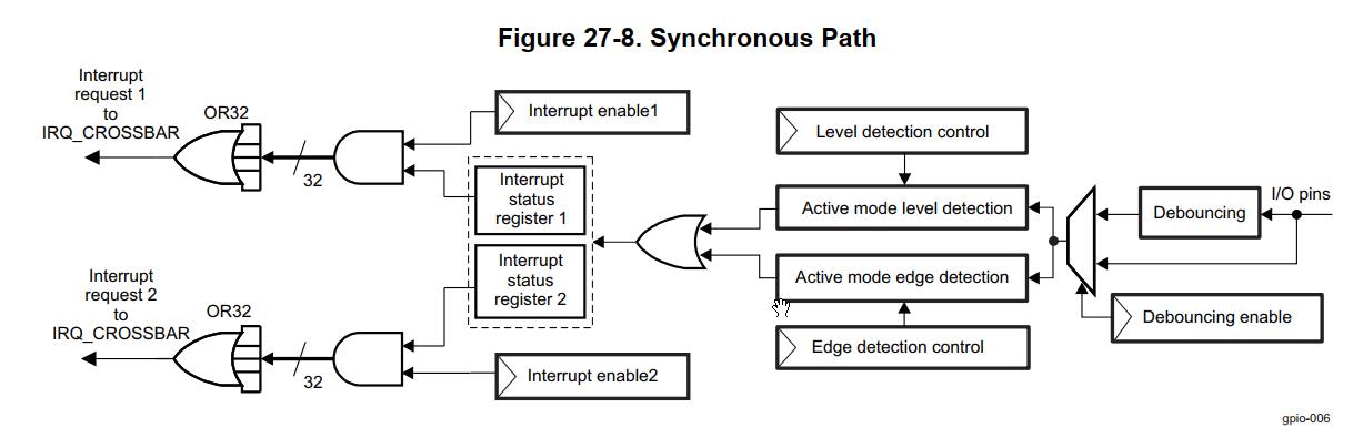
But in the figure 27-8 of the mentioned TRM there is no distinction between IRQs, both are routed to the IRQ_CROSSBAR.
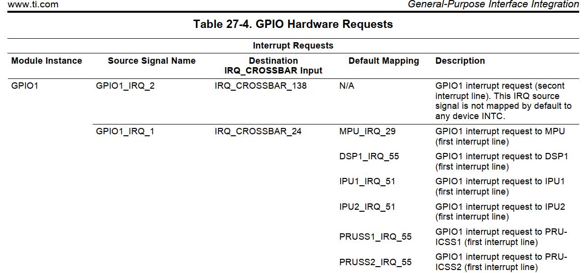
Again, in the table Table 27-4. GPIO Hardware Requests there is a distinction between _1 and _2 IRQs, but both of them are routed to the IRQ_CROSSBAR.
What is the purpose of separating _1 and _2 IRQs? Could you provide me with an example of the usage of this feature, please?
Thanks a lot for your support!