Other Parts Discussed in Thread: AM3356,
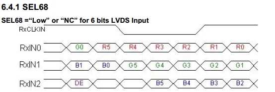
Hi, I want to understand the RGB output mapping for different color bit width mode. In TRM document table 11-84, for example, under 16-bit output mode, the higher bit is discarded but keep lower bit, so we will have R4~R0, G5~G0, B4~B0 output. This looks align with some LCD spec which requires those bits: R0~R5, G0~G5, B0~B5 in RGB666 mode(note: we will manually feed R5 by R4 signal, B5 by B4 signal, so that it become a RGB666. please see below screen shot on the LCD spec.
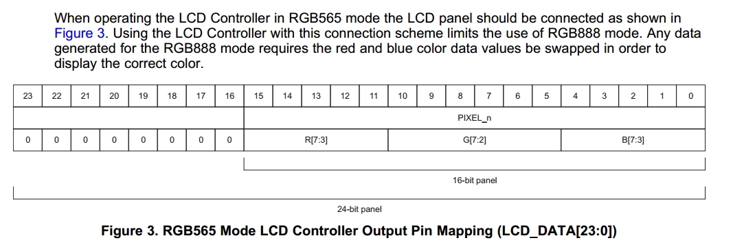
However, when I look into AM3356 RGB output mapping mentioned in errata SPRZ360, section 3.1.1, it states R7~R3, G7~G2, B7~B3 is output under RGB565 mode. It looks like AM3356 behaves different from AM5728. AM3356 discard lower bit of each R, G, B, while AM5728 discard higher bit of RGB. Is this understanding correct? If yes, then how to connect AM3356 to those LCD requires R0~R5, G0~G5, B0~B5 input?
Also, what confuse me is that normally we want to keep higher bit of as much as possible in order to keep larger color dynamic range, then what AM5728 did is keep lower bit, while AM3356 looks more make sense.


