This thread has been locked.

If you have a related question, please click the "Ask a related question" button in the top right corner. The newly created question will be automatically linked to this question.

Linux/AM4376: LPDDR2 autoinitialization issue

Part Number: AM4376

Tool/software: Linux

Hi SIr 

We used LPDDR2 (EDB8132B4PB) for AM4376 and would like to optimize DDR timing by using CCS. 

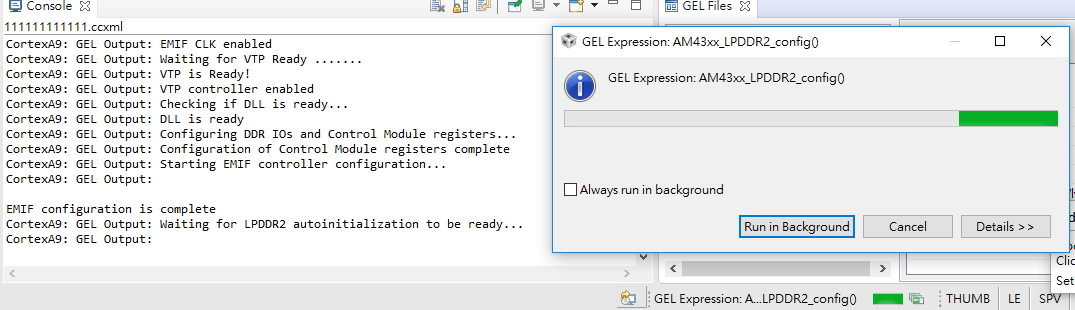
We found the CCS is waiting for LPDDR2 autoinitialization  for a long time and cannot finish successfully

GEL modification 

//========================================================================//

//********************************************************************************
//********************************************************************************
// LPDDR2 Initialization
//********************************************************************************
//********************************************************************************
#define LPDDR2_ADDRCTRL_WD0_IOCTRL_VALUE 0x00000000 //no pullup/down on addr/ctrl
#define LPDDR2_ADDRCTRL_WD1_IOCTRL_VALUE 0x00000000 //no pullup/down on addr/ctrl
#define LPDDR2_ADDRCTRL_IOCTRL_VALUE 0x00000294 //Slew rate: fast, Impedance: 44ohms, no pullup/down
#define LPDDR2_DATA0_IOCTRL_VALUE 0x20000294 //Slew rate: fast, Impedance: 44ohms, pullup on DQSn, pulldown on DQS
#define LPDDR2_DATA1_IOCTRL_VALUE 0x20000294 //Slew rate: fast, Impedance: 44ohms, pullup on DQSn, pulldown on DQS
#define LPDDR2_DATA2_IOCTRL_VALUE 0x20000294 //Slew rate: fast, Impedance: 44ohms, pullup on DQSn, pulldown on DQS
#define LPDDR2_DATA3_IOCTRL_VALUE 0x20000294 //Slew rate: fast, Impedance: 44ohms, pullup on DQSn, pulldown on DQS


//timings for 266MHz LPDDR2 (8Gb)
#define LPDDR2_PHY_CTRL 0x0E288006 //0x0E284006 //for 266MHz LPDDR2

#define LPDDR2_SDRAM_TIMING1 0xEA86B411 //0xEA86B411
#define LPDDR2_SDRAM_TIMING2 0x103A0E8A //0x103A0E8A
#define LPDDR2_SDRAM_TIMING3 0x5F6BA37F //0x0F6BA37F
//#define LPDDR2_SDRAM_CONFIG 0x808052BA //16-bit LPDDR2
#define LPDDR2_SDRAM_CONFIG 0x808012B3


#define LPDDR2_REF_CTRL 0x0000040D //266 * 3.9us = 0x40d
#define LPDDR2_ZQ_CONFIG 0x5007FA67 //0x50074BE4

//========================================================================//

SPRAC70A_AM437x_EMIF_Configuration_Tool_V21_Micron.xlsx

please advise.


  • The GEL is waiting for a specific value (0x18) from MR0 in the LPDDR2 to indicate that there is no error condition and the initialization is complete.  This byte is read on DQ[7:0].  If the layout of your board is not 1-to-1  (ie, AM437x DQ0 = DDR DQ0, AM437x DQ1 = DDR DQ1), then that value will be different.  

    You can include a GEL_TextOut function to see what is being read, and see if that corresponds with the layout of DQ0-7.

    The other possibility is that the DDR is not get initialized properly because of a bad configuration.  Check the point above first, and then we can check configuration issue if that did not solve the problem.

    Regards,

    James  

  • Hi Sir 

    Thanks for your reply.

    I found it halted in below code of GEL files

    //at this point, we can check the MR0 register of the LPDDR2 memory to ensure auto-initialization in memory is complete
    //when complete, DAI should be 0x0, RZQI should be 0x3
    //check memory datasheet for definition of these bits

    GEL_TextOut("Waiting for LPDDR2 autoinitialization to be ready...\n");
    GEL_TextOut("\n");
    WR_MEM_32(EMIF_LPDDR2_MODE_REG_CFG,0x00000000);
    while((RD_MEM_32(EMIF_LPDDR2_MODE_REG_DATA) & 0xFF) != 0x18);
    GEL_TextOut("LPDDR2 autoinitialization complete!\n");

    if we ignore below source code and add delay time, it can boot sucessfully

    //while((RD_MEM_32(EMIF_LPDDR2_MODE_REG_DATA) & 0xFF) != 0x18);

    We also implement this method in u-boot and it worked.

    in DDR spec, it described as below 

    4. MRRs and Device Auto Initialization (DAI) Polling
    After tINIT4 is satisfied (Te), only MRR commands and power-down entry/exit commands are supported. After Te, CKE can go LOW in alignment with power-down entry
    and exit specifications (see Power-Down).
    The MRR command can be used to poll the DAI bit, which indicates when device auto
    initialization is complete; otherwise, the controller must wait a minimum of tINIT5 or
    until the DAI bit is set before proceeding.
    Because the memory output buffers are not properly configured by Te, some AC parameters must use relaxed timing specifications before the system is appropriately configured.
    After the memory device sets the DAI bit (MR0, DAI) to zero, indicating DAI complete,
    the device is in the idle state (Tf). DAI status can be determined by issuing the MRR
    command to MR0.
    The device sets the DAI bit no later than tINIT5 after the RESET command. The controller must wait at least tINIT5 or until the DAI bit is set before proceeding

    if we ignore above description to check register and add delay times.

    Does it have any side effect ?

    please advise,

    BR

    Yimin

  • Yimin, if you change the while loop like this

    while((RD_MEM_32(EMIF_LPDDR2_MODE_REG_DATA) & 0xFF) != 0x18)

    {

        GEL_TextOut("MODE_REG_DATA = %x\n",,,,,RD_MEM_32(EMIF_LPDDR2_MODE_REG_DATA) );

    }

    You can see what is being read by the processor.  It is better to use the DAI status bit, otherwise, you cannot be sure the LPDDR2 was initialized properly.

    Regards,

    James