This thread has been locked.

If you have a related question, please click the "Ask a related question" button in the top right corner. The newly created question will be automatically linked to this question.

PCIe interrupt set in RC-mode

Part Number: TMS320C6678
Other Parts Discussed in Thread: SYSBIOS

Tool/software: Code Composer Studio

Hi

I'm testing PCIe interrupt for the PCIEXpress_Legacy_INTA.

MCSDK 2.1.2.6

CCS 8.3

Example project : C:\ti\pdk_C6678_1_1_2_6\packages\ti\drv\exampleProjects\PCIE_exampleProject

I added isr routine and setting(in cfg) in the PCIE_exampleProject

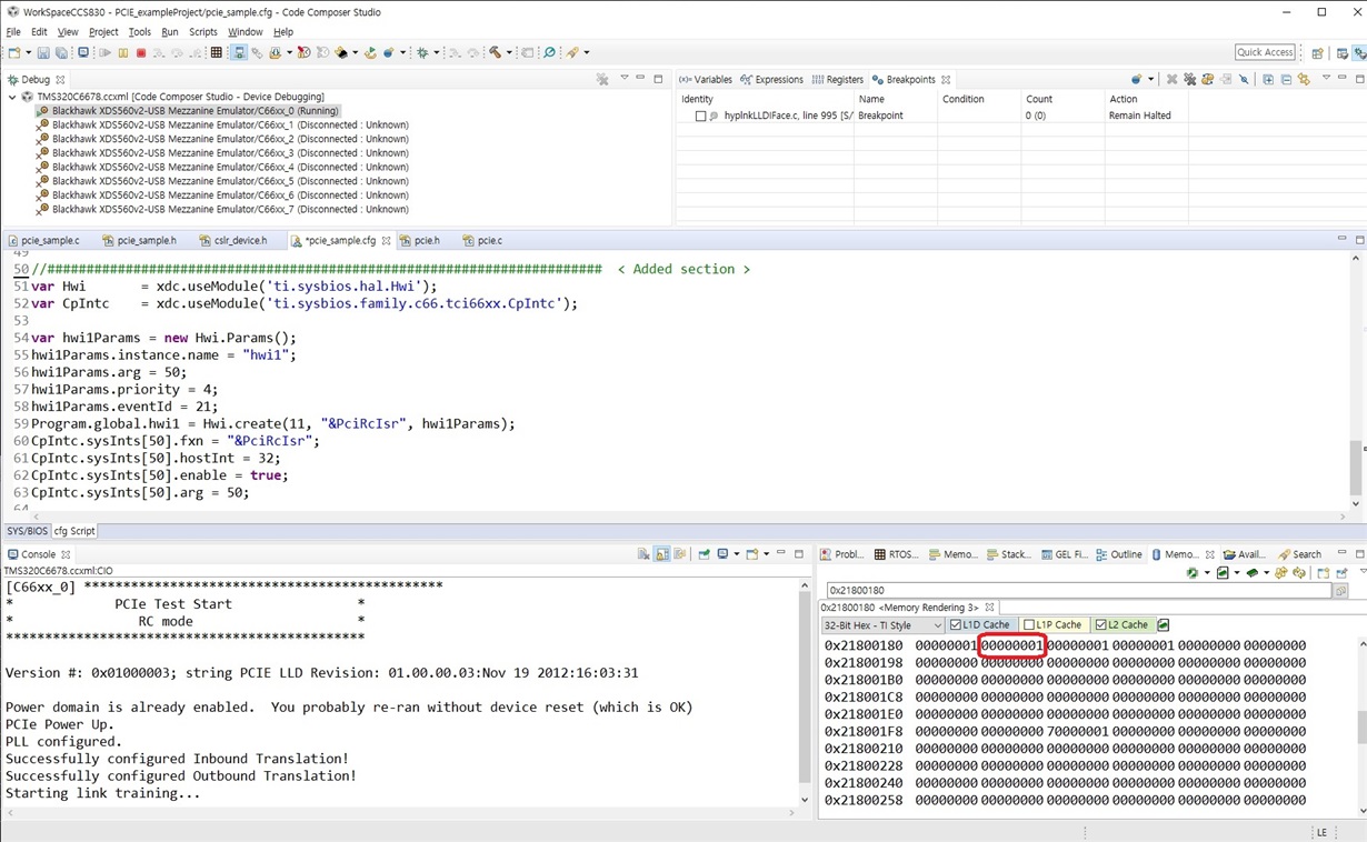
< Added cfg set-up and PCIe interrupt status(memory browser) >

As see abobe occure interrupt but not work ISR

The above experiment is intended to menual test incoming interrupts using RC mode in a PCIe example project with evmc6678.

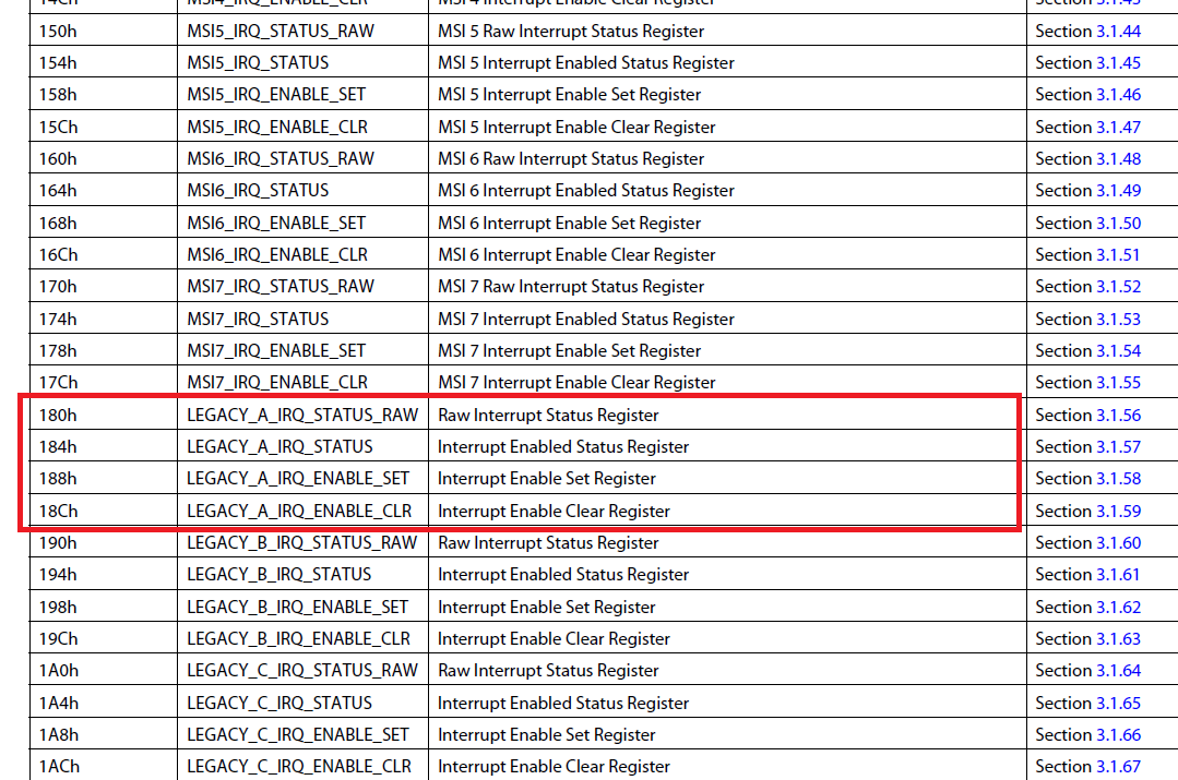
A manual interrupt was generated and tested using 1 in the Raw Interrupt Status Register (0x21800180).

In the example provided, the Interrupt Enabled Status Register shows that an interrupt has occurred.
However, they did not jump to ISR.

Need an other settings?

  • Hi,

    MCSDK is obsolete and please use the Processor SDK RTOS for C6678. We already have the PCIE interrupt test for INTA and MSI, see the http://software-dl.ti.com/processor-sdk-rtos/esd/docs/latest/rtos/index_device_drv.html#pcie

    Regards, Eric

  • Hi.

    Thank you for your answer.

    PCIe not use in the  Processor SDK use product.

    PCIe use in the MCSDK use product.

    The customer requests an interrupt code
    Customer was used as a polling as shown as see the example provided.
     
    So I'm trying to test the interrupt method, but I can't execute ISR.

    The 6678 content is not visible on the site provided.

    Is there PCIe example project in the Processor SDK??

    I'll check to see if there's an example of 6678 if you're for work tomorrow.
    I'll see PCIe example project in Processor SDK.

    Thank you.

  • Hi,

    It is PCIE_evmc6678_wSoCFile_C66BiosExampleProject or PCIE_evmc6678_wSoCLib_C66BiosExampleProject inside the Processor SDK RTOS for C667x.

    Regards, Eric

  • Thank you for your information.

    I saw the project through the information sent, but I can't see INTA settings and Interrupt Service Routine (ISR).

    In the notes to the project, i saw following information:
     - EVM EP sends 10 MSI and 10 INTA's to EVM RC (on certificate device and core combination)


    Please tell me the INTA settings and ISR location. ??

    Please tell me reason not be execute ISR. ??
    As see above test screen shot occured interrupt INTA. but not execute ISR. EOI is 0 in the RC-mode (INTA interrupt)

    I'm confused PCIe register informaion. but datasheet first use...

    < pcie.h > application register structure

    < datasheet >

  • Hi,

    I am sorry, there is no PCIE interrupt example for Keystone device. The existing ones (10 INTA, 10 MSI) are for the AM57 and AM65.

    But we still tested the PCIE interrupt on C66x devices (it is between a Linux PC and a C667x), you can look at the \mcsdk_2_01_02_06\tools\boot_loader\examples\pcie\pcieboot_interrupt\src\pcieboot_interrupt.c.

    Although this is a boot example, but you can extract the setup code for you (the code is not big): those platform init, UART you can ignore. There is an ISR also.

    Then, how do you generate an interrupt from Linux side: there is inside mcsdk_2_01_02_06\tools\boot_loader\examples\pcie\linux_host_loader\pciedemo.c

    /* Note: From PCIE specification, legacy interrupts cannot be generated from RC and be passed downstream.
    The example below is just making use of the facility that RC can access EP side register to generate
    a generic interrupt on local (EP) side using one of the event inputs of Interrupt Controller (INTC).
    There is no real interrupt signal sent over the PCIe link */
    printk ("Generating interrupt to DSP ...\n");
    iowrite32(1, ptrReg + LEGACY_A_IRQ_STATUS_RAW/4);

    This is actually by setting the IRQ_STATUS_RAW register. Without the Linux machine, I believe you just write the local DSP  IRQ_STATUS_RAW, you should enter the ISR.

    Regards, Eric

  • Hi.

    Thank you for your reply.

    As you can see from the screen I tested, interrupts also occurred. (In RC-Mode)
    (LEGACY A Interrupt Enabled Status Register 0x000001)
    And I saw interrupt mapping, but there's nothing wrong. (cfg)

    There must be something I don't know.
    I asked why ISR was not implemented, but I can't understand the answer.

    I'll investigate further.

  • Hi,

    In the pcie_sample.c, there is no ISR code for the C667x. We didn't develop that.

    In the \mcsdk_2_01_02_06\tools\boot_loader\examples\pcie\pcieboot_interrupt\src\pcieboot_interrupt.c, there is ISR code and interrupt is hooked by using CSL level code. The PCIE INTA is system interrupt 50, this is a second interrupt input to CIC0, the CIC0 output is CIC0_OUT3 on core 0. This is connected to VectID = 4. This is code was tested and should work.

    I saw you configured the interrupt using SYSBIOS, system interrupt 50=====> CIC0_OUT32. You may try the CSL level code first and debug why your way didn't work. Also there is a WIKI http://processors.wiki.ti.com/index.php/Configuring_Interrupts_on_Keystone_Devices you can refer.

    Regards, Eric

  • Hi.

    Thank you for your answer.

    I'll check your answers.

    I was testing without an EP by setting up RC-mode with evmc6678.
    It was a test to confirm whether the ISR was executed.

    During the data survey, I could see the contents of a similar test.
    e2e.ti.com/.../223849

    ISR runs only were received through PCIe lines, it said.

    Is correct??

    I thought the ISR needed to be implemented without an EP.

    I'll investigate further.

  • Hi,

    "ISR runs only were received through PCIe lines, it said."

    "I thought the ISR needed to be implemented without an EP."======> In the real world, the EP sends the interrupt to RC. The INTA/B/C/D and MSI are in-band signals in PCIE, this is to emulate the dedicated interrupt lines for INTA/B/C/D in the legacy PCI. You don't need EP to develop your ISR code, but how do you plan to test it working? Ideally you use two board, one is RC and the other is EP for this test.

    If you only have one board, for debug purpose how ISR worked, you may use one C6678 as the RC (without the EP), and manually (or code) change the LEGACY_A_IRQ_STATUS_RAW register. 

    Regards, Eric

  • Hi.

    Thank you for your reply.

    The above test screen used 1 in the LEGACY_A_IRQ_STATUS_RAW register to confirm that there was an interrupt (1) in the LEGACY_A_IRQ_STATUS register.
    However, the ISR was not implemented.

    I'm preparing the code in advance before I visit the customer.(Use one evmc6678 board)

    When ISR code is confirmed, it is planning to visit customers and test customer board (RC) and FPGA (EP).
    Since only ISR has not been executed, it is expected to be an interrupt mapping setup problem. The existing PCIE_interrupt example settings that you answered and my existing settings did not run ISR either.

    I have a question.
    In Status and Command Register (+1004h), Bit19 is INT_STAT. Indicates interrupt reception.

    Interrupts occurred (1) on LEGACY_A_IRQ_STATUS, but INT_STAT is 0. It cannot be set to 1 because it has read properties only.

    Isn't this bit related to the execution of Interrupt ISR?

    I think I'm doing something wrong or unknown...

    I'll investigate further.

  • Hi,

    I am not sure how exact you merged the C:\ti\pdk_C6678_1_1_2_6\packages\ti\drv\exampleProjects\PCIE_exampleProject and the  \mcsdk_2_01_02_06\tools\boot_loader\examples\pcie\pcieboot_interrupt\src\pcieboot_interrupt.c code together.

    As you still have issue to test PCIE ISR using one C6678 card, I tried to make this to work.

    I used the pdk_c667x_2_0_13, which is the latest Processor SDK RTOS 5.3 release, it is expected to be the same as MCSDK 2.1.2.6 on this topic, as it is legacy code 7-8 years old and not changed. My code change is inside pcie_sample.c, see the code called TEST_ISR. I linked the project with CSL libraries under: pdk_c667x_2_0_13\packages\ti\csl\lib\c6678\c66\release. 

    I tested 10 INTA, you will see the console print:

    **********************************************
    * PCIe Test Start *
    * EP mode *
    **********************************************

    Version #: 0x02030003; string PCIE LLD Revision: 02.03.00.03:Apr 6 2019:02:51:16

    Power domain is already enabled. You probably re-ran without device reset (which is OK)
    PCIe Power Up.
    PLL configured.
    Successfully configured Inbound Translation!
    Successfully configured Outbound Translation!
    Starting link training...
    Debug: GEM-INTC Configuration...

    Debug: GEM-INTC Configuration Completed

    Debug: CPINTC-0 Configuration...

    Debug: CPINTC-0 Configuration Completed

    DSP receives interrupt from host 1.
    DSP receives interrupt from host 2.
    DSP receives interrupt from host 3.
    DSP receives interrupt from host 4.
    DSP receives interrupt from host 5.

    .....

    Given this is a single C6678 board testing, it doesn't matter you are EP or RC. The code writes to PCIE_LEGACY_A_IRQ_STATUS_RAW to simulate there is an interrupt come in, then ISR should be entered. And after clearing the interrupt, the ISR should be entered again when new interrupts come in. You can set a break point at line: 

    DEVICE_REG32_W(PCIE_LEGACY_A_IRQ_STATUS_RAW, 0x1);

    and

    static void test_isr_handler(void* handle)

    to see how this worked.

    Note this is just an engineer code example and not TI official release. Hope you can use this as reference for your customer visit and good luck!

    I will be out of office for a few weeks and return 07/22, it is unlikely you will get further support for this topic during my absence. But I made the PCIE ISR working with a single board, this should unblock you.

    Attached is the code I changed and CCS project.

    PCIE_evmc6678_wSoCFile_C66BiosExampleProject.zip

    0383.pcie_sample.c

    Regards, Eric

  • Thank you very much.

    It was not a problem with ISR(cfg) and ISR(CSL) settings.

    ISR(cfg) set in PCIE sampleProject did not work.

    When I tested on the new SYS/BIOS project, I was able to check the motion right away.

    Have a good day. Until the day you come back. (--)(__);