This thread has been locked.

If you have a related question, please click the "Ask a related question" button in the top right corner. The newly created question will be automatically linked to this question.

C6747 Slave Boot

Now I want to use one C6747 to boot another C6747 with SPI Slave boot mode.

My question is, what's the RECV_START (receive-start-word) in the step of Start-Word Synchronization (SWS)?

My reference PDF is "sprabb1a-Using the TMS320C6747-45-43 Bootloader (Rev. A)".

And XMT_START (transmit-start-word ) is 0x5853 & 0x5253. But I can't find what the RECV_START (receive-start-word)  exactly is.

Thanks! O(∩_∩)O~

  • Hi Lian,

    RECV_START is an acknowledgement given by device to the host. It indicates that device has received XMT_START sent by the host.


    Best Regards,

    Ankit Agrawal

  • Thanks for your reply. I want to know the exact content of RECV_START. Is it 0x5253 & 0x5253? I have to program my code. Is that right?

    while(1)

    {

    SendData_16bits(0x5853);

    SendData_16bits(0x5253);

    Recv_Start1 = ReceiveData_16bits();

    Recv_Start2 = ReceiveData_16bits();

    if ( 0x5253 == Recv_Start1 && 0x5253== Recv_Start2 )

    break;

    }


  • Hi Lian,

    Have you checked that two data can be transmitted from the host? As mentioned by you, the two data transmitted by you are 0x5853 and 0x5253. Kindly check this. I am not sure of this.

    But for RECV_START, it is0x5253, as for all receive the opcode starts with 0x52.


    Best Regards,

    Ankit Agrawal


  • Thanks for your reply. I will explain it more clearly.

    I want to use one C6747 to boot another C6747. I set the host DSP's SPI as a MASTER, CLK is 250KHz. MSB(Most significant bit is shifted out first). SPI data word length is 16bits.

    According the PDF "sprabb1a-Using the TMS320C6747-45-43 Bootloader (Rev. A)" P19,  the original text is,

    "For the SPI and I2C slave modes, the bootloader operates the SPI/I2C peripheral in 16-bit mode, so that both start words are 16-bit (0x5853 & 0x5253). "

    And according The Note in P20 which says,

    so I should sent the data 0x5253 first, then 0x5853. I have observed my sending data through an oscilloscope. They're all right.

    But I didn't receive any data from the slave DSP.

    Do you have any suggestion? 

    Kindly get back to me as soon as possible! Thanks!

  • Lian,

    The XMT_START dat will be 0x5853, and the expected response, RCV_START, will be 0x5253.  For the master device to receive the data from the slave, the host needs to send dummy bits to the slave equal to the number of bits you expect to receive.  This is because the SPI data is simultaneously clocked in and out of the shift registers.

     So the start word exchnage looks like the following

    Host Sends      Host Recieves

    0x5853                 0xXXXX

    0xXXXX                 0x5253

    Then the ping opcode will start like the following

    Host Sends      Host Recieves

    0x590B                0xXXXX

    0x5853                 0xXXXX

    0xXXXX                 0x590B

    0xXXXX                 0x5253

    0x000N                 0xXXXX

    0xXXXX                 0x0000N

    ...

    And the op-code sync is basically the same as the first part of the ping op-code sync.

    Hope this helps.

    Regards, Daniel

  • Thanks a lot! Your reply helps me understand the process of slave boot.

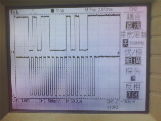
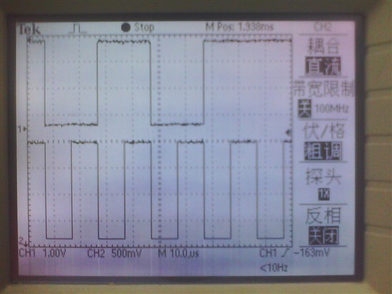
    Just as I said in the prior post, I set the SPI in Master mode, 16-bits, MSB. When I set my SPI CLOCK as 250KHz and send the 0x5853, there is no reply from the slave C6747.

    Then I set the CLOCK as 50KHz now. The specific sending process is as follows, The sending data is 0x5853. Why not the slave C6747 reponse? Can you give me any suggestion? Thanks very much!


  • I have another doubt about the SPI boot. 

    In the PDF "sprabb1a-Using the TMS320C6747-45-43 Bootloader (Rev. A)" P22, there is a Note,

    "Sufficient delay" is how long?  several hundred ns? or others?

    Please reply as quickly as possible!O(∩_∩)O~ Thanks!

  • Thanks a lot!  I know the reason. Because in C6747, SPI0 pins is also Boot pins, so when I connect the 2 SPI0 between 2 DSPs,  the 2 DSPs effect each other.