This thread has been locked.

If you have a related question, please click the "Ask a related question" button in the top right corner. The newly created question will be automatically linked to this question.

RTOS/AM3352: EDMA constant src address config

Part Number: AM3352

Tool/software: TI-RTOS

Hi

        I want to read FPGA data through EDMA.

The source data is a FIFO, that is to say, unchanged address.

How should I set the parameters of EDMA?

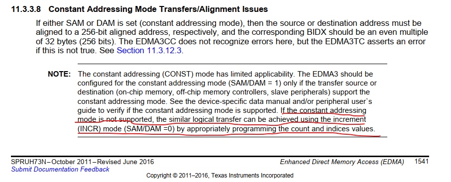
in the technical manual of AM3352, I found this passage

NOTE: The constant addressing (CONST) mode has limited applicability. The EDMA3 should be
configured for the constant addressing mode (SAM/DAM = 1) only if the transfer source or
destination (on-chip memory, off-chip memory controllers, slave peripherals) support the
constant addressing mode. See the device-specific data manual and/or peripheral user`s
guide to verify if the constant addressing mode is supported. If the constant addressing
mode is not supported, the similar logical transfer can be achieved using the increment
(INCR) mode (SAM/DAM =0) by appropriately programming the count and indices values

it means I can program the count and indices values to solve my issue.

I tried to set the srcbidx and srccidx to 0,but it failed.

can you give me some suggestions?

my PDK version is pdk_am335x_1_0_13.

BR

  • Hi.

    "For SAM in constant addressing mode, you must program the source address to be aligned to a 256-bit aligned address (5 LSBs of address must be 0)."

    Would it be possible your source address is not aligned?

    Also do you have increment mode work properly?

    Regards,

    Garrett

  • Hi Garrett

            my source address is 0x800000a,it is not aligned,and the data from the source address is a FIFO.

    the dest address is array.I shoulid read about 770*8 data from the FIFO.

    from this information, I know I must set the count and indices values by using the increment mode.

    I have tried many parameters,such as acnt,bcnt,ccnt,srcbidx,srccidx,desbidx and desbidx,but all of these are failed.

    this is my config which I think is right,but in fact, it is failed.

    acnt = 1;
    bcnt = data_len;//read data length
    ccnt = 1;

    srcbidx = 0;
    srccidx = 0;

    desbidx = 1;
    descidx = 1;

    So I have to ask for official support.I don't know the correct parameteres.

    BR!

  • Hi Garrett

           Is there any update today?

    BR!

  • Hi,

    That's correct - you must use increment mode and program the count and indices values.

    In the thread - You were able to get the EDMA working but only not able to get it triggered by GPIO event?

    The EDMA3 FAQ (www.ti.com/lit/an/sprac52/sprac52.pdf) may help clarify a few things.

    Regards,
    Garrett

  • If you're still having issues I recommend posting your complete Parameter RAM set as well as the results of attempting to use them, e.g. if you're getting data in the wrong order, etc. then please describe what you're seeing and what you expected it to look like.

  • Hi Garrett

           I can only read the firs dart right,the second data is 0,

    I posted the source code, I call the interface as follows:

     Radar_gpmc_edma_read(GPMC_ADDRESS+5*2,(uint32_t)dstBuff1,4)),

    I want to read 2 16bit datas from the fifo which address is GPMC_ADDRESS+5*2.

    GPMC_ADDRESS is the FPGA ADDRESS and 5*2 is the offset of the FIFO. I can only get the first data right.

    int32_t Radar_gpmc_edma_read(uint32_t srcaddr,uint32_t destaddr,uint32_t data_len)
    {
    EDMA3_DRV_Result result = EDMA3_DRV_SOK;
    uint32_t chId = EDMA3_DRV_DMA_CHANNEL_ANY;
    uint32_t tcc = EDMA3_DRV_TCC_ANY;
    uint32_t BRCnt = 0;
    int srcbidx = 0, desbidx = 0;
    int srccidx = 0, descidx = 0;
    uint32_t acnt = data_len;
    uint32_t bcnt = 1;
    uint32_t ccnt = 1;

    EDMA3_DRV_SyncType syncType;

    result = Edma3_CacheInvalidate(destaddr, (acnt*bcnt*ccnt));
    if(result != EDMA3_DRV_SOK)
    {
    Radar_log("\n Edma3_CacheInvalidate unsuccessful\n");
    }

    acnt = 2;
    bcnt = data_len/2;
    ccnt = 1;

    srcbidx = 0;
    srccidx = 0;

    desbidx = acnt;
    descidx = acnt;

    syncType = EDMA3_DRV_SYNC_A;


    /* Set B count reload as B count. */
    BRCnt = bcnt;

    result = EDMA3_DRV_requestChannel (handle_edma, &chId, &tcc,
    (EDMA3_RM_EventQueue)0,
    NULL, NULL);
    if(result != EDMA3_DRV_SOK)
    {
    Radar_log("\n EDMA3_DRV_requestChannel failed\n");
    }

    result = EDMA3_DRV_setSrcParams (handle_edma, chId, (uint32_t)srcaddr,
    EDMA3_DRV_ADDR_MODE_INCR,
    EDMA3_DRV_W16BIT);
    if(result != EDMA3_DRV_SOK)
    {
    Radar_log("\n EDMA3_DRV_setSrcParams failed result is %d\r\n\n",result);
    }

    result = EDMA3_DRV_setDestParams (handle_edma, chId, (uint32_t)(destaddr),
    EDMA3_DRV_ADDR_MODE_INCR,
    EDMA3_DRV_W16BIT);
    if(result != EDMA3_DRV_SOK)
    {
    Radar_log("\n EDMA3_DRV_setDestParams failed\n");
    }

    result = EDMA3_DRV_setSrcIndex (handle_edma, chId, srcbidx, srccidx);
    if(result != EDMA3_DRV_SOK)
    {
    Radar_log("\n EDMA3_DRV_setSrcIndex failed\n");
    }

    result = EDMA3_DRV_setDestIndex (handle_edma, chId, desbidx, descidx);
    if(result != EDMA3_DRV_SOK)
    {
    Radar_log("\n EDMA3_DRV_setDestIndex failed\n");
    }

    result = EDMA3_DRV_setTransferParams (handle_edma, chId, acnt, bcnt, ccnt,
    BRCnt, syncType);
    if(result != EDMA3_DRV_SOK)
    {
    Radar_log("\n EDMA3_DRV_setTransferParams failed\n");
    }

    result = EDMA3_DRV_setOptField (handle_edma, chId,
    EDMA3_DRV_OPT_FIELD_STATIC, 0u);
    if(result != EDMA3_DRV_SOK)
    {
    Radar_log("\n EDMA3_DRV_setOptField failed EDMA3_DRV_OPT_FIELD_STATIC\n");
    }

    result = EDMA3_DRV_setOptField (handle_edma, chId,
    EDMA3_DRV_OPT_FIELD_TCINTEN, 1u);
    if(result != EDMA3_DRV_SOK)
    {
    Radar_log("\n EDMA3_DRV_setOptField failed EDMA3_DRV_OPT_FIELD_TCINTEN\n");
    }

    result = EDMA3_DRV_setOptField (handle_edma, chId,
    EDMA3_DRV_OPT_FIELD_ITCINTEN, 1u);
    if(result != EDMA3_DRV_SOK)
    {
    Radar_log("\n EDMA3_DRV_setOptField failed EDMA3_DRV_OPT_FIELD_ITCINTEN\n");
    }

    result = EDMA3_DRV_enableTransfer (handle_edma, chId,EDMA3_DRV_TRIG_MODE_MANUAL);
    if (result != EDMA3_DRV_SOK)
    {
    Radar_log ("edma3_test_poll_mode: EDMA3_DRV_enableTransfer " \
    "Failed, error code: %d\r\n", result);
    }

    /* Wait for the Completion Bit to be SET in the IPR/IPRH register. */
    result = EDMA3_DRV_waitAndClearTcc (handle_edma, tcc);
    if (result != EDMA3_DRV_SOK)
    {
    Radar_log ("edma3_test_poll_mode: EDMA3_DRV_waitAndClearTcc " \
    "Failed, error code: %d\r\n", result);
    }

    /* Free the previously allocated channel. */
    result = EDMA3_DRV_freeChannel (handle_edma, chId);
    if (result != EDMA3_DRV_SOK)
    {
    Radar_log("edma3_test_poll_mode: EDMA3_DRV_freeChannel() FAILED, " \
    "error code: %d\r\n", result);
    }

    return result;
    }

  • The sync type should be AB instead of A. Otherwise it will only transfer ACNT bytes which is what you are observing.

  • One other tip...  Since you're performing manual cache operations (invalidate), make sure your destination buffer:

    1. Is aligned to a cache line boundary.
    2. Is sized as a multiple of a cache line.

    You want to be sure no other data can reside by unhappy accident in that same cache line or you may cause issues.  For Cortex A8 a cache line is 64 bytes.