This thread has been locked.

If you have a related question, please click the "Ask a related question" button in the top right corner. The newly created question will be automatically linked to this question.

TDA3XEVM: Vision SDK ADC Buffer Format and 1FFT Buffer Format

Part Number: TDA3XEVM
Other Parts Discussed in Thread: AWR1243

HI,

I would like to find out the buffer format of 2 sets of data in the processing flow in Vision SDK.

1. ADC buffer format - what does it look like when this buffer is captured in the issCapture Link and is fed to the FFT link for example? Is this buffer a simple flat 1D buffer with no special structure in that doppler index 0 - range bins 0-255, doppler index 1 - range bins 0-255, etc...?

2. The 1st FFT Intermediate Buffer format? Is this simply a flat 1D buffer same as above?

Thanks,

--Khai

  • Khai,

    It is a flat 1D buffer for both ISS capture and 1D FFT output.

    One thing to note would be there is 32-byte alignment requirement specifically for the ISS capture which causes the pitch to be a multiple of 32 bytes. This means that if the width in bytes of the frame is not 32 byte aligned the next line would start at the next 32-byte boundary.

    In the radar case, a line is 4 (or how many every you have enabled) Rx antenna times number of ADC samples.

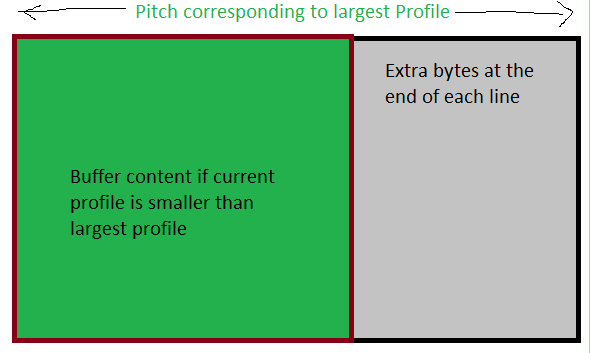
    The SDK code also takes care of the fact that you may have 2 profiles of different ADC sample widths, In this case, the max-width is taken and that is used to calculate the pitch. So if you have more than one profile programmed at the same time to the AWR1243 the capture buffer would have larger pitch (hence holes) in the data.

    Thanks and Regards,

    Piyali

  • Hi Piyali,

    Just want to confirm my understanding of you comment above. So say if the ADC data for a frame is 128 chirps x 256 range bins where each range bin sample is a complex 16 bit I and 16 bit Q (4 bytes/sample). This results in 1 ADC line of 1024 bytes which is 32 byte aligned. Thus, the 128 ADC lines are back to back contiguously in a flat buffer.

    Thanks,

    --Khai

  • Yes, you are right. (Assuming you have only 1 profile)

    Thanks and Regards,

    Piyali

  • Can you elaborate the statement in quote? I do have 4 profiles config for the AWR1243. My understanding is that only 1 profile is active at any one time until it is changed and then the changed profile will become active. So ADC data coming into the IssCapature is for one profile.

    Thanks,

    --Khai

  • How is the ADC data arranged for 4 RX coming into the IssCapture?

    Thanks,

    --Khai

  • Khai,

    We have discussed this in our webex sessions in the past. If you have more than 1 profile which is configured during the usecase initialization, the framework would try and allocate the largest frame buffer corresponding to the number of profiles you have enabled. This is to make sure if you change profiles at run time, the buffer for capturing the data would be sufficient to capture the largest configuration. 

    This basically means the pitch would correspond to the largest ADC sample value in the profile configuration array. If the current profile is smaller than the largest you would see extra bytes at the end of the line.

    Thanks and Regards,

    Piyali

  • Hi Piyali,

    Please confirm my understanding for 1FFT in the intermediate buffer.

    1. Not required to be 32 bytes aligned

    2. Allocated for the largest profile frame size

    3. Follow the frame buffer line orientation for 4RX as in raw ADC data

    Thanks,

    --Khai

  • Khai

    Your understanding of all 3 points is right.

    Thanks and Regards,

    Piyali