


Part Number: AM5728
Other Parts Discussed in Thread: BEAGLEBOARD-X15
Hello,
we are trying to use the BeagleBoard-X15's McSPI4 with the Linux spidev driver (TI SDK 5.03), but we get some confusing signals on the MOSI line. SCLK and CE lines are working as expected.
Following is the Pinmux setup for McSPI4 generated with the pearl script:
{MMC3_DAT4, (M1 | PIN_OUTPUT_PULLUP)},	/* mmc3_dat4.spi4_sclk */
{MMC3_DAT5, (M1 | PIN_OUTPUT_PULLUP)},	/* mmc3_dat5.spi4_d1 */
{MMC3_DAT6, (M1 | PIN_OUTPUT_PULLUP)},	/* mmc3_dat6.spi4_d0 */
{MMC3_DAT7, (M1 | PIN_OUTPUT_PULLUP)},	/* mmc3_dat7.spi4_cs0 */
The device tree node for McSPI/spidev:
&mcspi4 {
	pinctrl-names = "default";
	status = "okay";
	spidev@0{
		compatible = "rohm,dh2228fv";
		spi-max-frequency = <48000000>;
		reg = <0x0>;
		ti,pindir-d0-out-d1-in;
		#ti,pindir-d0-in-d1-out;
		status = "okay";
	};
};
And the output on MOSI line using linux/tools/spi/spidev_test.c:
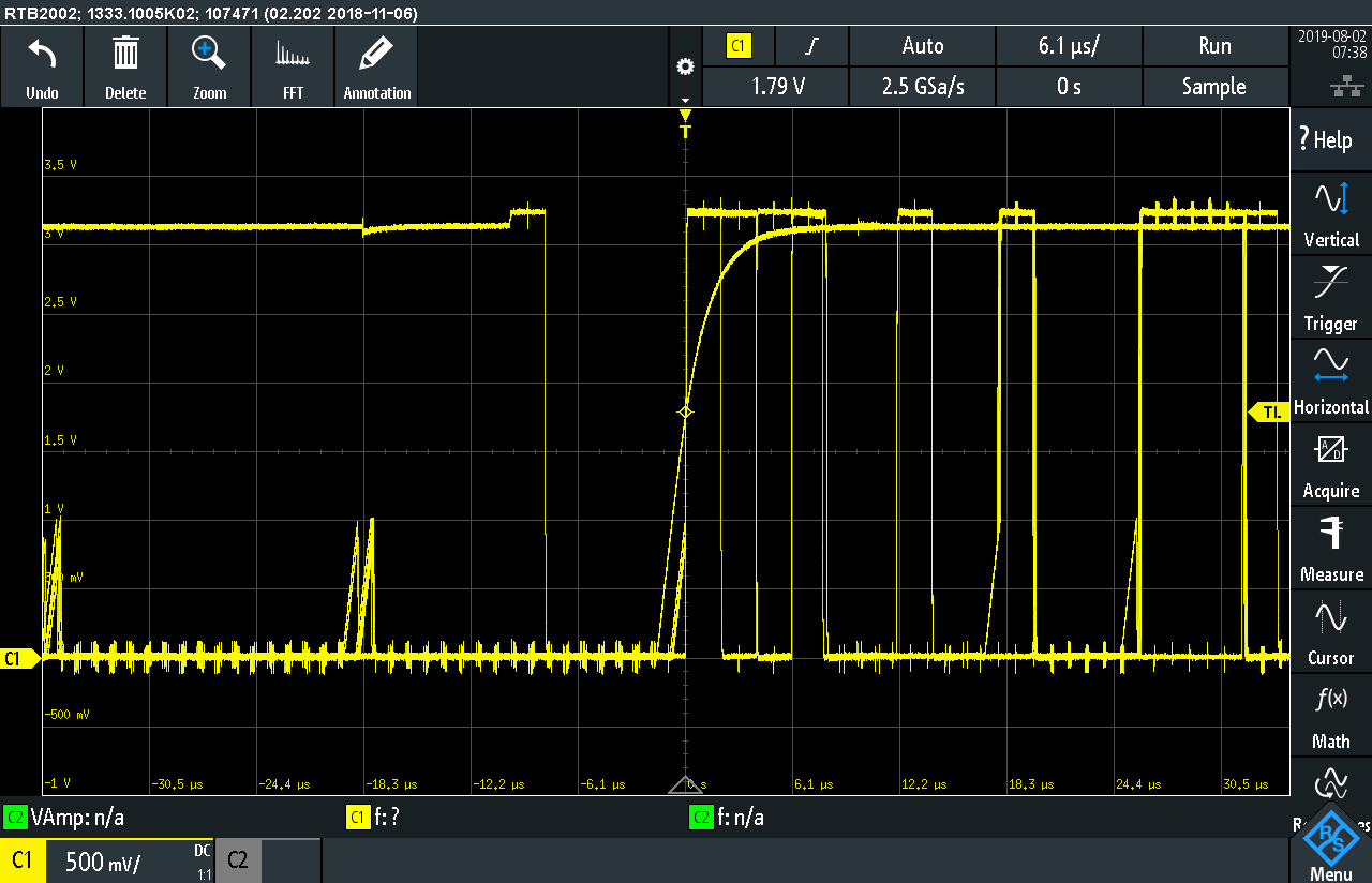
It seems like there are two signals on this pin? We are measuring directly on the expansion connectors using a Hirose FX18-60S-0.8SV15.
We also checked IO_SET4 with the same behaviour.
Another problem is, that there are no changes on the pins if we try to switch the SPI D0 and D1 pins for input and output using the out commented line in the device tree SPI node above.
Any hints on solving these problems?
Kind Regards,
Patrick


