This thread has been locked.

If you have a related question, please click the "Ask a related question" button in the top right corner. The newly created question will be automatically linked to this question.

66AK2G12: PCIE link training fail.

Part Number: 66AK2G12

Hi there!

Our application board(installed 66ak2g12) use pciess for transfer data between PC system and DSP.

On most pc systems. there is no problem. board is controlled under windows OS via PCI express interface.

On some pc system, link training sequence is failed.

following is the LTSSM dump in pcieWaitLinkUp.

1) Success case : 

Starting link training...
Info[000000] : PCIE_DEBUG0[0x0c004a02], PCIE_DEBUG1[0x0800f700]
Info[000001] : PCIE_DEBUG0[0x03006211], PCIE_DEBUG1[0x08000010]
Link is up.

2) Fail case : 

(note ltssmState  is PCIE_DEBUG0, debug1 is PCIE_DEBUG1)

Starting link training...
Info[000000] : ltssmState[0x00004a02], debug1[0x08000000]
Info[000001] : ltssmState[0x0000bc42], debug1[0x08000000]
Info[000002] : ltssmState[0x00000002], debug1[0x08000000]
Info[000003] : ltssmState[0x00004a02], debug1[0x08000000]
Info[000004] : ltssmState[0x00000002], debug1[0x08000000]
Info[000005] : ltssmState[0x00004a02], debug1[0x08000000]
Info[000006] : ltssmState[0x00000002], debug1[0x08000000]
Info[000007] : ltssmState[0x0000f742], debug1[0x08000000]
Info[000008] : ltssmState[0x0000bc42], debug1[0x08000000]
Info[000009] : ltssmState[0x00004a02], debug1[0x08000000]
Info[000010] : ltssmState[0x00006402], debug1[0x08000000]
Info[000011] : ltssmState[0x00000202], debug1[0x08000000]
Info[000012] : ltssmState[0x00004a02], debug1[0x08000000]

....

Info[000667] : ltssmState[0x00004a02], debug1[0x08000000]
Info[000668] : ltssmState[0x00006402], debug1[0x08000000]
Info[000669] : ltssmState[0x00004a02], debug1[0x08000000]
Info[000670] : ltssmState[0x0000bc42], debug1[0x08000000]
Info[000671] : ltssmState[0x00004a02], debug1[0x08000000]
Info[000672] : ltssmState[0x0000f742], debug1[0x08000000]
Info[000673] : ltssmState[0x0000bc43], debug1[0x08000000]
Info[000674] : ltssmState[0x00004a03], debug1[0x08000000]
Info[000675] : ltssmState[0x0000bc43], debug1[0x08000000]
Info[000676] : ltssmState[0x00004a03], debug1[0x08100000]
Info[000677] : ltssmState[0x0000bc43], debug1[0x08000000]
Info[000678] : ltssmState[0x0000b503], debug1[0x08000000]
Info[000679] : ltssmState[0x00004a03], debug1[0x08000000]
Info[000680] : ltssmState[0x0000bc43], debug1[0x08100000]
Info[000681] : ltssmState[0x0000b503], debug1[0x08000000]
Info[000682] : ltssmState[0x0000bc43], debug1[0x08100000]
Info[000683] : ltssmState[0x0000bc43], debug1[0x08000000]

....

finally, time out  exit and last ltssm is 0x03.

.

What can i do to solve this issue.

  • Hi,

    Could you share what are the differences between the pc systems? You say that PCIE link training fails only on some PC systems.

    Best Regards,
    Yordan

  • Thank you for reply.

    1. There is no significant difference between pc systems.
        The remarkable feature is the bus chip set is "H170" and Mother board is made of special specifications.

    2. A notable experimental result on this issue is that the SERDES register value is differs on between the success pc and the fail pc.
        < on normal PC system sequence >
        - PCIe ss power up

        - PCIE_PHY_PLL_CTRL:0x00000000 before Serdes initilization

        - Serdes initilization

        - PCIE_PHY_PLL_CTRL:0x10000000 after Serdes initilization

        - end mode application register setting

        - link wait

        - link up

        - .....

        < on Failed PC system >

        - PCIe ss power up

        - PCIE_PHY_PLL_CTRL:0x00000000 before Serdes initilization

        - Serdes initilization

        - PCIE_PHY_PLL_CTRL:0x10000001 after Serdes initilization

        - end mode application register setting

        - link wait  => time out


        Could you explain about this result of an experiment?  i can not fully understand with TRM.

       Thank you in advance.

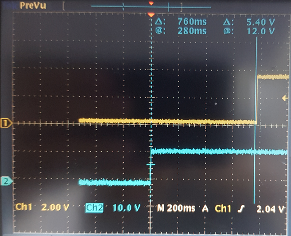
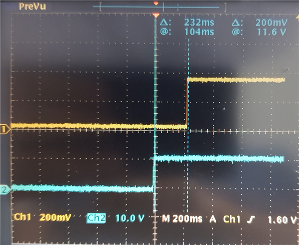
  • There is the Power up sequence timing difference between normal system and fail system.

    < figure 1 : normal system , CH2 : 12V power PCIE edge, CH1 : PERST# >


    < figure 2 : Fail system , CH2 : 12V power PCIE edge, CH1 : PERST# >

     The problem and solution list is

    1) PERST# connected to PORn of SOC ==> Cut PERST# and connect to user input to monitoring.

    2) PERST# activated time is too short to boot up SOC. ==> Request to BIOS vendor that change the PERST# active time to mininum 800mSec.

    3) Minimize the boot-up time(code optimize and so on)


    In my case, If the BIOS vendor reject the request, the project could be drop.
    So I think that People who want to use PCIeSS on TI-DSP to connect with various PC system have to consider this issue.

    And finally, I hardly hope that TI have to offer the technical reference manuals to USER who uses PCIeSS to connect with PC(desktop) systems.


    Good luck to TI users.!