This thread has been locked.

If you have a related question, please click the "Ask a related question" button in the top right corner. The newly created question will be automatically linked to this question.

TMS320C6678: Smart Reflex CVDD, VID Boot Failure

Part Number: TMS320C6678
Other Parts Discussed in Thread: LM10011, LM21215

In one of the C6678 based board we delivered to customer, we are facing a peculiar issue as described below,

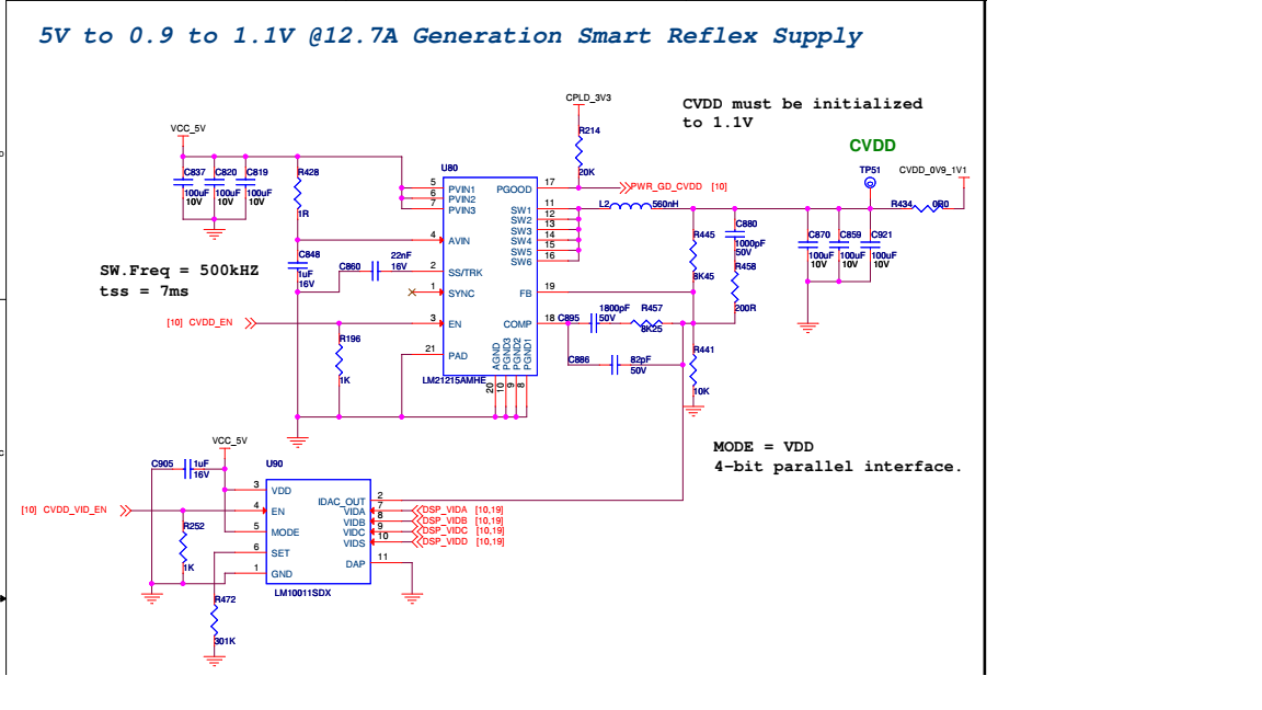
 Smart Reflex is disabled [VID is disabled]

  • Application is running in 8 different cores (8 different .out files), the same application is been tested in multiple other boards and it runs stable
  • Boot-loader loads Core#0 application, then Core#0 application will kick-start and run cores#1-7
  •  In this one particular board, whenever core#4 comes-up; the Processor is hanged and all the other cores stop running.
  • For experiment, we tried with different core clock frequency (from 100MHz to 1GHz),
    • All 8 cores are running stable for core clock frequency 100MHz to 850MHz
    • Beyond 850 MHz, core#4 issue is observed
    • When we try running remaining 7 cores (except core#4), all 7 cores are running stable even for 1GHz core clock
    • When we try running only core#0 and core#4 (only 2 cores), again the same issue is observed i.e. it is stable only upto 850MHz and beyond that processor is hanged.

As ,mentioned above, we have disabled the VID, because if we enable it, Core#0 itself is not able to boot up.

May I know SRVnom for the device ?

PS: Attaching the smart reflex circuitry. 

  • Hi,

    Take a look at Table 6-2Recommended Operating Conditions in the Datasheet, the SRVnom varies between device variants. Initially it should be 1.1V on bootup for 1000-MHz and 1250-MHz device and 1.15V for for 1400-MHz device. Then the values are as follows:
      0.85-1.1V for 1000 MHz device

      0.9-1.1V for 1250 MHz device

      0.95-1.15V for 1400 MHz device

    Best Regards,
    Yordan

  • Dear Yordan,

    Thank you for the reply.

    It would be really helpful if your address my other queries. 

  • If you mean analyzing the processor hang you described, when powering up core #4, my guess is that you have a voltage drop (or insufficient current) on CVDD power rail. Since this problem occurs in only one board, I suspect some pcb manufacturing fault in this particular board...

    Best Regards,
    Yordan

  • Yordan,

    We did measure the CVDD voltage rail at both source and load during below 3 occurrences

    1) DSP in reset

    2) DSP successfully booting

    3) Core getting hung

    All the time the load voltage was between 1.045V to 1.09V

    One weird observation is that if core booting fails during power on, then if it's rebooted after board getting warm up, then the cores successfully boots up.

    Please provide your input on this.

    Also we disabled VCNTL or VID as enabling this caused Core 0 to fail booting up.

    Thanks

    Shekhar

  • Shekhar,

    Please provide the measurements mentioned above for the board that is failing and for a board that is not failing.  Make sure that you are measuring the voltage across a decoupling capacitor directly under the center of the C6678 DSP.

    Please see the below post for accessing the VCNTLID on the processor:

    https://e2e.ti.com/support/processors/f/791/p/732932/2705652#2705652

    Tom

  • Shekhar,

    A few other comments:

    The DSP is not rated for operation at low speeds.  I am surprised that you had successful boot and execution below 750MHz.  The asynchronous bridges to high bandwidth interfaces will drop transactions at lower speeds.

    The difference in operation from board to board does point to a deficiency in the board design or manufacturing.  This will need attention.

    Tom

  • Dear Tom,

    Actually we have an design flaw.

    The MODE pin of LM10011 is been pulled high, which sets the mode to 4bit. But the C6678 support 6 bit VCNTL interface.

    Would this create a problem?

    As far as voltage measurement are considered with

    DSP operating speed: 1Ghz and

    Measurement: Across under DSP decoupling CAP

    we have made two scenarios.

    One is with disabling LM10011 and the other with enabling it.

    LM10011 Disabled

    Board 1:

    Booting: CVDD=1.06

    In Reset: CVDD=1.0975

    Board 2:

    Booting: CVDD=1.056

    In Reset: CVDD=1.09

    Board 3 (Failure Board, as only first three cores boots, and Core 4 gets hung)

    Booting: CVDD=1.056

    In Reset: CVDD=1.0975

    LM10011 Enabled

    Board 1:

    Booting: CVDD=0.997

    In Reset: CVDD=1.0975

    Board 2:

    Booting: CVDD=1.02

    In Reset: CVDD=1.09

    Board 3 (Failure Board, Core0 itself doesn't boot up)

    Booting: CVDD=1.009

    In Reset: CVDD=1.0975

    Do we need to doubt the smart reflex design or the DSP chip itself might have gone bad.

  • Shekhar,

    Yes, 6-bit VID is a requirement.  Yes, having the LM10011 in the wrong VID mode can cause problems and this must be fixed.  Please also post the VCNTLID values for these devices.

    Tom

  • Tom

    Thank you for the quick reply.

    At present MODE is connected to supply by PCB trace, we need to scratch the trace and connect a wire from MODE pin to GND pin.

    Regarding VCNTLID, we shall revert back tomorrow morning.

    By the way, could you please specify the address for reading these registers?

  • Shekhar,

    The address is shown in the linked e2e post and in the PSC user guide.  The VID value is readable from the VCNTLID register at 0235_0014h and extracted from bits 21:16.  Please refer to the PSC User Guide for the full register definition and the device Data Manual for the full address map.

    Tom

  • Dear Tom,

    Could we use any value of RSET resistor in between the range shown below for LM10011 design with LM21215

    For eg. 250k or 270k

  • Dear Tom and Yordan,

    We have new observation

    Core 0 booting fails

    • VID_EN [MODE pin of LM10011 is still pulled high]
    • SBL: 1Ghz [PLL settings are set to 1GHz]
    • Main Application: [PLL settings are disabled]

    Core 0 boots but Core4/5 fails to boot

    • VID_DIS [MODE pin of LM10011 is still pulled high]
    • Irrespective of PLL settings either in SBL or Main application

    All cores boots successfully

    • VID_EN [MODE pin of LM10011 is still pulled high]
    • SBL: Running @ default frequency [PLL settings are disabled]
    • Main Application: 1Ghz

  • Shekhar,

    The C6678 is rated for operation using a 6-bit VID.  You cannot meet all of the requirements using a 4-bit VID.  You will need to fix your board to allow this board to go into production.  Until then, you can force your prototypes to run at 1.1V to enable software development.  The parts may run a little hot but they will be functional in a lab environment with a lower ambient temperature.

    Please provide the VCNTLID values and measured CVDD voltages.  I am concerned that you might also have addition IR drop on your board that needs to be resolved.  At low ambient temperatures with nominal devices, I would expect them to operate at the reduced voltage provided by the 4-bit VID.  If there is not excessive IR drop in your power network, then I recommend analyzing the noise levels or the power supply loop compensation.  You could also have an issue with power supply voltage droops when the current draw changes rapidly.

    Tom

  • Dear Tom,

    With VID_EN, we have below details

    a) VCNTL reg : 11 0101 b => 1.039V

    b) Measured voltage across decap = 1.028V

    c) LM21215 + LM10011, as per board designed

    Reset=301k, Rfb1=8.45k, Rfb2=10k

    So theoretically calculated CVDD= 1.107 - 0.000507 = 1.106V.

    My weird observation is during board debugging, when VID was disabled, Core were hung, but after warm up they used to boot up, Any relevant reason?

    Thanks

  • Shekhar,

    Your observation supports my assertion that there may be more going on here.  Assuming the cause of the problem was AVS voltage levels, ALL devices should boot and operate reliably at normal ambient temperatures when the CVDD voltage is 1.100V.  Please disable VID control and verify that you have 1.1V across the decoupling capacitor.  You should then be able to operate the boards.  If they fail, you need to start looking for other causes such as noise or supply droop.  There may also be software issues.  Please verify your PLL programming.  The SYSCLKOUT pin should output the SYSCLK/6 or 166MHz when the core is operating at 1000MHz.

    Tom

  • Tom,

    One small doubt,

    CVDD shall be initially = 1.1V [When VID/LM10011 is disabled] 

    or

    CVDD shall be = 1.1V after VID/LM10011 enabled but still DSP has not come out of reset

    later adjust to the voltage requested by the Smart Reflex circuit in the KeyStone I device

  • Tom,

    * CVDD regulator of ours is designed for 1.107V [Initial Voltage]

    When VID is disabled, CVDD has below readings

    1] DSP in reset = 1.097V

    2] Immediately after power-on = 1.097V [reset is removed]

    3] After complete booting = 1.06V

    Please confirm whether the readings are fine.

  • Dear Tom,

    With VID enable,

    When I changed feedback resistor of LM21215, now the initial CVDD=1.12V @ load.

    Board started booting but inconsistently.

    Whenever board boots CVDD final value would be 1.06V.

    PS: Still MODE of LM10011 is in 4 bit VID mode.

    Please provide your feedback

  • Shekhar,

    Is the 1.06V value after booting due to the 4-bit AVS value or is the AVS latching disabled?  You cannot use 4-bit AVS.  This needs to be disabled so that the LM10011 never leaves its initial state.

    If you are measuring 1.120V with the C6678 part in reset and then boot with AVS disabled resulting in an operating CVDD value of 1.060V, that is a 60mV drop.  That is significant.  You probably need to add copper to the board to reduce the IR drop or properly implement remote sensing so that the static IR drop can be removed.

    Where are you making these CVDD measurements and with what type of meter?  Can you provide measurements for each condition both at the output of the power supply and across the CVDD decoupling cap directly beneath the C6678?

    Tom

  • Tom,

    AVS latching is enabled, but the LM10011 MODE is still in 4bit.

    Now when probed

    CVDD @load

    Initial power till board boots up, value varied from 1.12 to 1.06V

    CVDD @DSP BGA CAP (measured through digital multimeter)

    Initial power till board boots up, value varied from 1.12 to 1.06V

  • m1v2_cvdd_drops.xlsx

    Tom,

    Please find the table with voltage measurements for 3 boards, wherein one of the board is not booting.

    Do we need to replace the LM21215 with new or increase the feedback resistor ?

  • Shekhar,

    The table indicates that VID is disabled but you are still seeing significant voltage droop once the device starts drawing current.  Are you using remote sense?  If so, where is it attached?  Alternately, can you add a wire from the power supply output to a point close to the load to minimize the voltage loss?

    Can you add a column to the table showing the voltage measured at the power supply output at these same times?

    Tom

  • Dear Tom,

    CVDD voltage drop was observed immediately after 0R [jumper] resistor kept b/w CVDD regulator source and load. 
    So later, the 0R has been replaced by direct short through lead.  
    By this implementation, there is only 10mV drop as compared to 65mV earlier.
    This was due to the resistor being "0.01 OHM 1W". Since large amount of current was needed by the DSP core load, more voltage was dropped at the 0R itself.
    Remark:  DSP all cores were now booting on all the 3 boards [18481001, 18481002, 18483002] with the same checksum. 
    Thank you Tom, Yordan and Wade for your support.   
  • Shekhar,

    Good to see that you resolved your IR drop issue.  Once you revise the boards to enable 6-bit VID, your power solution should be good for production.

    Tom

  • Tom,

    The existing boards are production series itself.

    One more observation, during thermal cycling @ -20C, when board was re-booted, all core boots except core4. This was observed many times, but as soon as temp reached 55C, all core boots including core4. 

    CVDD voltage drop is less than 15mV.

    Any feedbacks ?

  • Shekhar,

    Nothing more than I have already stated.  The design needs to be revised to make it AVS compliant.  If this is not sufficient, then you need to review your power delivery network for IR drop and/or noise issues.  You may need to examine all of the supplies.

    Tom

  • Dear Tom,

    If we solve the IR drop issue, could we take this board for final delivery with VID disabled. To make it AVS compliant (change from 4 bit MODE to 6 bit MODE), we need to carry out much of a rework, which won't be allowed as per QA in the existing board.

    As this board (system) goes into missile application, so will there be any issues going forward?  

  • Shekhar,

    The C6678 is not rated for operation without a properly functional AVS power supply that supports Smart Reflex Class 0 operation with a 6-bit VID code as defined in the documentation.  Therefore, I cannot provide approval for use with AVS disabled and I cannot provide approval for operation with the LM10011 in 4-bit VID mode.

    Tom

  • Dear Tom,

    When I was glancing at the latest datasheet of LM21215, I got to know it had a Current Limit pin, but the old datasheet and reference design does not have such pin, instead as a Sync pin .

    Please clarify the query.

    Latest datasheet.      

    Old reference design:.

    (As attached in my first post of this thread )

  • Shekhar,

    What do you want to know?  You are posting to the processors forum.  If you want detailed discussion about features of the LM21215, you need to post questions to a power supply forum.  All power supply references on the processors forum came from the power supply experts.

    Tom

  • Dear Tom,

    If we still have IR drop of around 10mV, but increase the source voltage itself by 10mv so that we get expected CVDD @load and make AVS compliant design (VID enable) . Could we expect the design to work with all core booting?

    Thanks

    Shekhar

  • Shekhar,

    Raising the supply voltage by 10mv is acceptable.  The supply must always provide the required voltage at the CVDD pins.  This is assuming that you have an AVS compliant power supply that supports the 6-bit VID.

    Tom

  • Tom,

    We have now enabled AVS 6 bit mode.

    At load, Initial CVDD was 1.1V and  after DSP out of reset CVDD is 1.065V

    (VCNTLID = 11 1001) was read from 0x02350014h address

    Now, when the system was put under thermal cycling,

    Core 4 did not boot at -40C (negative temp). Also Core 0 did not boot at +65C(positive temp)

    We are not getting any clue, as now the power design is also as per recommendation.

  • Shekhar,

    I agree that the VID code listed should result in the voltage that you are measuring.  Is this measured at the power supply or under the load?  You indicated that the unit failed temp cycling testing.  How long did it cycle before it failed?  Are all boards failing during this testing or only certain boards?  How many boards do you have available for this testing?  Are they failing at the same rate?  Can you monitor the CVDD voltage during this testing?  What voltages do you see at the temperature extremes and when it fails?  Each time the device boots, the AVS voltage must reset to 1.1V and then be reprogrammed by the AVS 6-bit VID code.  Does it always result in the same value?  If you adjust the nominal voltage output from the CVDD supply 10-20mV higher, does this change the probability of failure? 

    Tom

  • Dear Tom,

    Measured CVDD voltage is @ load. 

    At high temp [>55C], in one cycle itself board is failing. And also only one board among 3 is failing. 

    We monitored below parameters during high temp

    1] CVDD @ load

    2] DDR3 voltage

    3] System and DDR clock

    All the parameters are fine.

    And each time device is booted, AVS is reset to 1.1V and then to smart reflex value.

    And we have no voltage drop now. 

    Still we are not able to boot application @ high temp

    Few observations:

    1] Power-on before board is soaked @ high temp : Board is working continuously

    2] Power-on after soaked for 30 min @ high temp: Board is not booting

    a. If 1GHz PLL setting is in SBL, then board fails to boot

    b. If 1GHz PLL setting is after Core0 boots, then we are seeing no booting issue further

    Please provide your feedback. 

  • Shekhar,

    You are seeing this boot failure on a single board out of 3 that you are testing.  What is the failure rate(i.e. 3 of of 10 trials)?

    Please tell me more about this boot failure.  What is the boot sequence?  What memory or interface are you using to boot?  Is there a 2nd level boot loader?  What do you see with CCS when it fails?

    You say this failure is at high temp (>55C).  Is this the ambient temp?  What is the case temp of the C6678 at the time it fails?  What is the case temp of the SDRAM?

    Tom

  • Dear Tom,

    One board which is failing is at almost 8 out of 10 trials

    DSP boots from NOR flash through EMIF16 interface.

    Boot Sequence:

    SBL boots from flash with some frequency

    Then it copies each Core content of flash to DDR3

    Then SBL launches Core0 through entry point of DDR3

    SBL makes PLL setting to 1GHz

    Core0 boots up with 1GHz

    Then Core0 launches all other 7 cores from their respective DDR3 entry points

    Failure occurs at high temperature when Core0 executes from DDR3 and fails in that.

    But this occurs only when PLL settings are in 1GHz

    As soon as make PLL settings with lesser frequency it boots even at higher temperature.

    55C is ambient temp, whereas DSP case may be at around 85C

    We are using Hi-Rel DSP.

    Case temperature of SDRAM is unknown.

  • Shekhar,

    You should make accurate measurements of the case temp.  You need to have a thermo-couple directly touching the case.  If you are using a heatsink (which I believe is a necessity), you will need to drill a hole or cut a notch into the heatsink to allow this to be inserted.  You may be surprised by the measurement.

    Measuring the temperature of the SDRAM is also important.  It is normally only rated for 85C unles you have extended temp parts and you are using an accelerated refresh rate.

    Please provide more details on the boot failure.  Where does the program crash?  Can you still access DDR from the failed core?  Or any other core?

    Tom

  • Tom,

    You may be surprised to hear that in one of our board, we are facing Core0 booting issue as soon as we enable smart reflex.

    We are totally stuck in finding where the issue is ?

    Our doubt is if with smart reflex disabled in board for few months and the board is used in continuous testing, will the DSP gets degraded??

    Has anyone faced the issue before ??

  • Tom,

    As mentioned , above board has issue at room temperature itself, not like the other system which had the issue at higher temperatures.

  • Hi Shekhar

    I wanted to let you know that Tom is out of office this week , on personal time off, so you can expect some delays in response.

    I tried to go through this thread but unfortunately it is now a bit long to get a quick jist of all outstanding issues. 

    Is it possible for you to capture the pass/fail scenarios in a table with some more description on boot failures.

    Parameters for the tables should be something like

    1) Number of boards ( I believe you have 3 boards?)

    2) Core # failing on each board

    3) Temperature for failure, you had some failing at negative temp, some at high temp and now some at room temp

    4) Pass/Fail conditions - seems like frequency, CVDD levels were making a difference?

    I see that you are suspecting that because SR was disabled on one of the boards, and now it stopped working at room temp, you are suspecting some device damage?

    It is hard to say if that should be the case - do you have other reasons to believe that the device is not working as expected (e.g. any post boot tests?) - does the failure change at low or high temp now?

    Details appreciated.

    Regards

    Mukul 

  • Dear Mukul,

    Does disabling smart reflex for longer period of time and continuing the testing for that period degrade the DSP.

    Because these boards had SR disabled for around 4 months and later with SR disabled chip had core booting issue even at room temperature.

    Now we got to know the importance of SR, so now we enabled SR and checked the DSP behavior, at little high temperature [around 60C] we are facing core booting issue.

    Please confirm whether the chip degradation results in above erratic behavior. 

  • Shekhar

    It is hard to say. You are only reporting boot failures, you have not clarified whether you are seeing other functional issues with the chip.

    It could simply be that during your testing you are doing something wrong to cause EOS type failures etc. You need to give us more data points on observed failures.