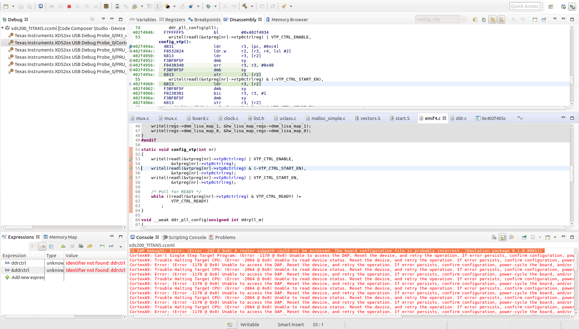
Part Number: AM4376
Hello,
I am trying to boot linux when I power up our custom board.
In order to do that, here is what I did so far :
- Since our board doesn't have an EEPROM, I hardcoded the name of the board to "AM43_IDK" in board/ti/common/board_detect.c
- I modified the IDK AM437x pinmux config according the one of our custom board in arch/arm/dts/arm437x-idk-evm.dts
- I modified the DDR3 configuration of the IDK AM437x in board/ti/am43xx/board.c with the configuration I generated with the AM437x EMIF Configuration Tool (which has been validated through CCS and Gel Files)
Then I generate a new U-boot and MLO by doing the following (in u-boot directory) :
- make CROSS-COMPILE=arm-linux-gnueabihf- distclean
- make CROSS-COMPILE=arm-linux-gnueabihf- O=My_Uboot am43xx_evm_defconfig
- make CROSS-COMPILE=arm-linux-gnueabihf- O=My_Uboot
After that, I copy/paste the generated u-boot.img and MLO on the 'boot' partition of an SD card (which has been created using the create-sdcard.sh script)
When I power up the board with the SD card inserted nothing happens on the serial console (The Minicom setup has been verified)
Am I missing something or am I doing something wrong ?
I am using sdk Linux-RT am437x-evm 06.00.00.07.
Regards,
Gilles
// SPDX-License-Identifier: GPL-2.0+
/*
 * board.c
 *
 * Board functions for TI AM43XX based boards
 *
 * Copyright (C) 2013, Texas Instruments, Incorporated - http://www.ti.com/
 */

#include <common.h>
#include <environment.h>
#include <i2c.h>
#include <linux/errno.h>
#include <spl.h>
#include <usb.h>
#include <asm/omap_sec_common.h>
#include <asm/arch/clock.h>
#include <asm/arch/sys_proto.h>
#include <asm/arch/mux.h>
#include <asm/arch/ddr_defs.h>
#include <asm/arch/gpio.h>
#include <asm/emif.h>
#include <asm/omap_common.h>
#include "../common/board_detect.h"
#include "board.h"
#include <power/pmic.h>
#include <power/tps65218.h>
#include <power/tps62362.h>
#include <miiphy.h>
#include <cpsw.h>
#include <linux/usb/gadget.h>
#include <dwc3-uboot.h>
#include <dwc3-omap-uboot.h>
#include <ti-usb-phy-uboot.h>

DECLARE_GLOBAL_DATA_PTR;

static struct ctrl_dev *cdev = (struct ctrl_dev *)CTRL_DEVICE_BASE;

/*
 * Read header information from EEPROM into global structure.
 */
#ifdef CONFIG_TI_I2C_BOARD_DETECT
void do_board_detect(void)
{
	/* Ensure I2C is initialized for EEPROM access*/
	gpi2c_init();
	if (ti_i2c_eeprom_am_get(CONFIG_EEPROM_BUS_ADDRESS,
				 CONFIG_EEPROM_CHIP_ADDRESS))
		printf("ti_i2c_eeprom_init failed\n");
}
#endif

#ifndef CONFIG_SKIP_LOWLEVEL_INIT

const struct dpll_params dpll_mpu[NUM_CRYSTAL_FREQ][NUM_OPPS] = {
	{	/* 19.2 MHz */
		{125, 3, 2, -1, -1, -1, -1},	/* OPP 50 */
		{-1, -1, -1, -1, -1, -1, -1},	/* OPP RESERVED	*/
		{125, 3, 1, -1, -1, -1, -1},	/* OPP 100 */
		{150, 3, 1, -1, -1, -1, -1},	/* OPP 120 */
		{125, 2, 1, -1, -1, -1, -1},	/* OPP TB */
		{625, 11, 1, -1, -1, -1, -1}	/* OPP NT */
	},
	{	/* 24 MHz */
		{300, 23, 1, -1, -1, -1, -1},	/* OPP 50 */
		{-1, -1, -1, -1, -1, -1, -1},	/* OPP RESERVED	*/
		{600, 23, 1, -1, -1, -1, -1},	/* OPP 100 */
		{720, 23, 1, -1, -1, -1, -1},	/* OPP 120 */
		{800, 23, 1, -1, -1, -1, -1},	/* OPP TB */
		{1000, 23, 1, -1, -1, -1, -1}	/* OPP NT */
	},
	{	/* 25 MHz */
		{300, 24, 1, -1, -1, -1, -1},	/* OPP 50 */
		{-1, -1, -1, -1, -1, -1, -1},	/* OPP RESERVED	*/
		{600, 24, 1, -1, -1, -1, -1},	/* OPP 100 */
		{720, 24, 1, -1, -1, -1, -1},	/* OPP 120 */
		{800, 24, 1, -1, -1, -1, -1},	/* OPP TB */
		{1000, 24, 1, -1, -1, -1, -1}	/* OPP NT */
	},
	{	/* 26 MHz */
		{300, 25, 1, -1, -1, -1, -1},	/* OPP 50 */
		{-1, -1, -1, -1, -1, -1, -1},	/* OPP RESERVED	*/
		{600, 25, 1, -1, -1, -1, -1},	/* OPP 100 */
		{720, 25, 1, -1, -1, -1, -1},	/* OPP 120 */
		{800, 25, 1, -1, -1, -1, -1},	/* OPP TB */
		{1000, 25, 1, -1, -1, -1, -1}	/* OPP NT */
	},
};

const struct dpll_params dpll_core[NUM_CRYSTAL_FREQ] = {
		{625, 11, -1, -1, 10, 8, 4},	/* 19.2 MHz */
		{1000, 23, -1, -1, 10, 8, 4},	/* 24 MHz */
		{1000, 24, -1, -1, 10, 8, 4},	/* 25 MHz */
		{1000, 25, -1, -1, 10, 8, 4}	/* 26 MHz */
};

const struct dpll_params dpll_per[NUM_CRYSTAL_FREQ] = {
		{400, 7, 5, -1, -1, -1, -1},	/* 19.2 MHz */
		{400, 9, 5, -1, -1, -1, -1},	/* 24 MHz */
		{384, 9, 5, -1, -1, -1, -1},	/* 25 MHz */
		{480, 12, 5, -1, -1, -1, -1}	/* 26 MHz */
};

const struct dpll_params epos_evm_dpll_ddr[NUM_CRYSTAL_FREQ] = {
		{665, 47, 1, -1, 4, -1, -1}, /*19.2*/
		{133, 11, 1, -1, 4, -1, -1}, /* 24 MHz */
		{266, 24, 1, -1, 4, -1, -1}, /* 25 MHz */
		{133, 12, 1, -1, 4, -1, -1}  /* 26 MHz */
};

const struct dpll_params gp_evm_dpll_ddr = {
		50, 2, 1, -1, 2, -1, -1};

static const struct dpll_params idk_dpll_ddr = {
	400, 23, 1, -1, 2, -1, -1
};

static const u32 ext_phy_ctrl_const_base_lpddr2[] = {
	0x00500050,
	0x00350035,
	0x00350035,
	0x00350035,
	0x00350035,
	0x00350035,
	0x00000000,
	0x00000000,
	0x00000000,
	0x00000000,
	0x00000000,
	0x00000000,
	0x00000000,
	0x00000000,
	0x00000000,
	0x00000000,
	0x00000000,
	0x00000000,
	0x40001000,
	0x08102040
};

const struct ctrl_ioregs ioregs_lpddr2 = {
	.cm0ioctl		= LPDDR2_ADDRCTRL_IOCTRL_VALUE,
	.cm1ioctl		= LPDDR2_ADDRCTRL_WD0_IOCTRL_VALUE,
	.cm2ioctl		= LPDDR2_ADDRCTRL_WD1_IOCTRL_VALUE,
	.dt0ioctl		= LPDDR2_DATA0_IOCTRL_VALUE,
	.dt1ioctl		= LPDDR2_DATA0_IOCTRL_VALUE,
	.dt2ioctrl		= LPDDR2_DATA0_IOCTRL_VALUE,
	.dt3ioctrl		= LPDDR2_DATA0_IOCTRL_VALUE,
	.emif_sdram_config_ext	= 0x1,
};

const struct emif_regs emif_regs_lpddr2 = {
	.sdram_config			= 0x808012BA,
	.ref_ctrl			= 0x0000040D,
	.sdram_tim1			= 0xEA86B411,
	.sdram_tim2			= 0x103A094A,
	.sdram_tim3			= 0x0F6BA37F,
	.read_idle_ctrl			= 0x00050000,
	.zq_config			= 0x50074BE4,
	.temp_alert_config		= 0x0,
	.emif_rd_wr_lvl_rmp_win		= 0x0,
	.emif_rd_wr_lvl_rmp_ctl		= 0x0,
	.emif_rd_wr_lvl_ctl		= 0x0,
	.emif_ddr_phy_ctlr_1		= 0x0E284006,
	.emif_rd_wr_exec_thresh		= 0x80000405,
	.emif_ddr_ext_phy_ctrl_1	= 0x04010040,
	.emif_ddr_ext_phy_ctrl_2	= 0x00500050,
	.emif_ddr_ext_phy_ctrl_3	= 0x00500050,
	.emif_ddr_ext_phy_ctrl_4	= 0x00500050,
	.emif_ddr_ext_phy_ctrl_5	= 0x00500050,
	.emif_prio_class_serv_map	= 0x80000001,
	.emif_connect_id_serv_1_map	= 0x80000094,
	.emif_connect_id_serv_2_map	= 0x00000000,
	.emif_cos_config			= 0x000FFFFF
};

const struct ctrl_ioregs ioregs_ddr3 = {
	.cm0ioctl		= 0x00000084,				/*modifié!!!!!!!*/
	.cm1ioctl		= 0x00000000,				/*modifié!!!!!!!*/
	.cm2ioctl		= 0x00000000,				/*modifié!!!!!!!*/
	.dt0ioctl		= 0x00000084,				/*modifié!!!!!!!*/
	.dt1ioctl		= 0x00000084,				/*modifié!!!!!!!*/
	.dt2ioctrl		= 0x00000084,				/*modifié!!!!!!!*/
	.dt3ioctrl		= 0x00000084,				/*modifié!!!!!!!*/
	.emif_sdram_config_ext	= 0x0002c163,				/*modifié!!!!!!!*/
};

const struct emif_regs ddr3_emif_regs_400Mhz = {
	.sdram_config			= 0x61a05332,			/*modifié!!!!!!!*/
	.ref_ctrl			= 0x00000c30,			/*modifié!!!!!!!*/
	.sdram_tim1			= 0xeaaad4d3,			/*modifié!!!!!!!*/
	.sdram_tim2			= 0x266b7fda,			/*modifié!!!!!!!*/
	.sdram_tim3			= 0x5f7f867f,			/*modifié!!!!!!!*/
	.read_idle_ctrl			= 0x00050000,			/*modifié!!!!!!!*/
	.zq_config			= 0x50077d33,			/*modifié!!!!!!!*/
	.temp_alert_config		= 0x00000000,			/*modifié!!!!!!!*/
	.emif_ddr_phy_ctlr_1		= 0x00048009,			/*modifié!!!!!!!*/
	.emif_ddr_ext_phy_ctrl_1	= 0x00040100,			/*modifié!!!!!!!*/
	.emif_ddr_ext_phy_ctrl_2	= 0x00000000,			/*modifié!!!!!!!*/
	.emif_ddr_ext_phy_ctrl_3	= 0x00000000,			/*modifié!!!!!!!*/
	.emif_ddr_ext_phy_ctrl_4	= 0x00000000,			/*modifié!!!!!!!*/
	.emif_ddr_ext_phy_ctrl_5	= 0x00000000,			/*modifié!!!!!!!*/
	.emif_rd_wr_lvl_rmp_win		= 0x00000000,			/*modifié!!!!!!!*/
	.emif_rd_wr_lvl_rmp_ctl		= 0x80000000,			/*modifié!!!!!!!*/
	.emif_rd_wr_lvl_ctl		= 0x00000000,			/*modifié!!!!!!!*/
	.emif_rd_wr_exec_thresh		= 0x00000405,			/*modifié!!!!!!!*/
	.emif_prio_class_serv_map	= 0x00000000,			/*modifié!!!!!!!*/
	.emif_connect_id_serv_1_map	= 0x00000000,			/*modifié!!!!!!!*/
	.emif_connect_id_serv_2_map	= 0x00000000,			/*modifié!!!!!!!*/
	.emif_cos_config		= 0x00ffffff			/*modifié!!!!!!!*/
};

/* EMIF DDR3 Configurations are different for beta AM43X GP EVMs */
const struct emif_regs ddr3_emif_regs_400Mhz_beta = {
	.sdram_config			= 0x61a05332,			/*modifié!!!!!!!*/
	.ref_ctrl			= 0x00000c30,			/*modifié!!!!!!!*/
	.sdram_tim1			= 0xeaaad4d3,			/*modifié!!!!!!!*/
	.sdram_tim2			= 0x266b7fda,			/*modifié!!!!!!!*/
	.sdram_tim3			= 0x5f7f867f,			/*modifié!!!!!!!*/
	.read_idle_ctrl			= 0x00050000,			/*modifié!!!!!!!*/
	.zq_config			= 0x50077d33,			/*modifié!!!!!!!*/
	.temp_alert_config		= 0x0,				/*modifié!!!!!!!*/
	.emif_ddr_phy_ctlr_1		= 0x00048009,			/*modifié!!!!!!!*/
	.emif_ddr_ext_phy_ctrl_1	= 0x00040100,			/*modifié!!!!!!!*/
	.emif_ddr_ext_phy_ctrl_2	= 0x00000000,			/*modifié!!!!!!!*/
	.emif_ddr_ext_phy_ctrl_3	= 0x00000000,			/*modifié!!!!!!!*/
	.emif_ddr_ext_phy_ctrl_4	= 0x00000000,			/*modifié!!!!!!!*/
	.emif_ddr_ext_phy_ctrl_5	= 0x00000000,			/*modifié!!!!!!!*/
	.emif_rd_wr_exec_thresh		= 0x80000405,			/*modifié!!!!!!!*/
	.emif_prio_class_serv_map	= 0x80000001,			/*modifié!!!!!!!*/
	.emif_connect_id_serv_1_map	= 0x00000000,			/*modifié!!!!!!!*/
	.emif_connect_id_serv_2_map	= 0x00000000,			/*modifié!!!!!!!*/
	.emif_cos_config		= 0x00ffffff			/*modifié!!!!!!!*/
};

/* EMIF DDR3 Configurations are different for production AM43X GP EVMs */
const struct emif_regs ddr3_emif_regs_400Mhz_production = {
	.sdram_config			= 0x638413B2,
	.ref_ctrl			= 0x00000C30,
	.sdram_tim1			= 0xEAAAD4DB,
	.sdram_tim2			= 0x266B7FDA,
	.sdram_tim3			= 0x107F8678,
	.read_idle_ctrl			= 0x00050000,
	.zq_config			= 0x50074BE4,
	.temp_alert_config		= 0x0,
	.emif_ddr_phy_ctlr_1		= 0x0E004008,
	.emif_ddr_ext_phy_ctrl_1	= 0x08020080,
	.emif_ddr_ext_phy_ctrl_2	= 0x00000066,
	.emif_ddr_ext_phy_ctrl_3	= 0x00000091,
	.emif_ddr_ext_phy_ctrl_4	= 0x000000B9,
	.emif_ddr_ext_phy_ctrl_5	= 0x000000E6,
	.emif_rd_wr_exec_thresh		= 0x80000405,
	.emif_prio_class_serv_map	= 0x80000001,
	.emif_connect_id_serv_1_map	= 0x80000094,
	.emif_connect_id_serv_2_map	= 0x00000000,
	.emif_cos_config		= 0x000FFFFF
};

static const struct emif_regs ddr3_sk_emif_regs_400Mhz = {
	.sdram_config			= 0x638413b2,
	.sdram_config2			= 0x00000000,
	.ref_ctrl			= 0x00000c30,
	.sdram_tim1			= 0xeaaad4db,
	.sdram_tim2			= 0x266b7fda,
	.sdram_tim3			= 0x107f8678,
	.read_idle_ctrl			= 0x00050000,
	.zq_config			= 0x50074be4,
	.temp_alert_config		= 0x0,
	.emif_ddr_phy_ctlr_1		= 0x0e084008,
	.emif_ddr_ext_phy_ctrl_1	= 0x08020080,
	.emif_ddr_ext_phy_ctrl_2	= 0x89,
	.emif_ddr_ext_phy_ctrl_3	= 0x90,
	.emif_ddr_ext_phy_ctrl_4	= 0x8e,
	.emif_ddr_ext_phy_ctrl_5	= 0x8d,
	.emif_rd_wr_lvl_rmp_win		= 0x0,
	.emif_rd_wr_lvl_rmp_ctl		= 0x00000000,
	.emif_rd_wr_lvl_ctl		= 0x00000000,
	.emif_rd_wr_exec_thresh		= 0x80000000,
	.emif_prio_class_serv_map	= 0x80000001,
	.emif_connect_id_serv_1_map	= 0x80000094,
	.emif_connect_id_serv_2_map	= 0x00000000,
	.emif_cos_config		= 0x000FFFFF
};

static const struct emif_regs ddr3_idk_emif_regs_400Mhz = {		/*a priori la config est bonne*/
	.sdram_config			= 0x61a05332,			/*modifié!!!!*/
	.sdram_config2			= 0x00000000,			/*modifié!!!!*/
	.ref_ctrl			= 0x00000c30,			/*modifié!!!!*/
	.sdram_tim1			= 0xeaaad4d3,			/*modifié!!!!*/
	.sdram_tim2			= 0x266b7fda,			/*modifié!!!!*/
	.sdram_tim3			= 0x5f7f867f,			/*modifié!!!!*/
	.read_idle_ctrl			= 0x00050000,			/*modifié!!!!*/
	.zq_config			= 0x50077d33,			/*modifié!!!!*/
	.temp_alert_config		= 0x00000000,			/*modifié!!!!*/
	.emif_ddr_phy_ctlr_1		= 0x00048009,			/*modifié!!!!*/
	.emif_ddr_ext_phy_ctrl_1	= 0x00040100,			/*modifié!!!!*/
	.emif_ddr_ext_phy_ctrl_2	= 0x00000000,			/*modifié!!!!*/
	.emif_ddr_ext_phy_ctrl_3	= 0x00000000,			/*modifié!!!!*/
	.emif_ddr_ext_phy_ctrl_4	= 0x00000000,			/*modifié!!!!*/
	.emif_ddr_ext_phy_ctrl_5	= 0x00000000,			/*modifié!!!!*/
	.emif_rd_wr_lvl_rmp_win		= 0x00000000,			/*modifié!!!!*/
	.emif_rd_wr_lvl_rmp_ctl		= 0x80000000,			/*modifié!!!!*/
	.emif_rd_wr_lvl_ctl		= 0x00000000,			/*modifié!!!!*/
	.emif_rd_wr_exec_thresh		= 0x00000405,			/*modifié!!!!*/
	.emif_prio_class_serv_map	= 0x00000000,			/*modifié!!!!*/
	.emif_connect_id_serv_1_map	= 0x00000000,			/*modifié!!!!*/
	.emif_connect_id_serv_2_map	= 0x00000000,			/*modifié!!!!*/
	.emif_cos_config		= 0x00ffffff			/*modifié!!!!*/
};

void emif_get_ext_phy_ctrl_const_regs(const u32 **regs, u32 *size)
{
	if (board_is_eposevm()) {
		*regs = ext_phy_ctrl_const_base_lpddr2;
		*size = ARRAY_SIZE(ext_phy_ctrl_const_base_lpddr2);
	}

	return;
}

const struct dpll_params *get_dpll_ddr_params(void)
{
	int ind = get_sys_clk_index();

	if (board_is_eposevm())
		return &epos_evm_dpll_ddr[ind];
	else if (board_is_evm() || board_is_sk())
		return &gp_evm_dpll_ddr;
	else if (board_is_idk())
		return &idk_dpll_ddr;

	printf(" Board '%s' not supported\n", board_ti_get_name());
	return NULL;
}


/*
 * get_opp_offset:
 * Returns the index for safest OPP of the device to boot.
 * max_off:	Index of the MAX OPP in DEV ATTRIBUTE register.
 * min_off:	Index of the MIN OPP in DEV ATTRIBUTE register.
 * This data is read from dev_attribute register which is e-fused.
 * A'1' in bit indicates OPP disabled and not available, a '0' indicates
 * OPP available. Lowest OPP starts with min_off. So returning the
 * bit with rightmost '0'.
 */
static int get_opp_offset(int max_off, int min_off)
{
	struct ctrl_stat *ctrl = (struct ctrl_stat *)CTRL_BASE;
	int opp, offset, i;

	/* Bits 0:11 are defined to be the MPU_MAX_FREQ */
	opp = readl(&ctrl->dev_attr) & ~0xFFFFF000;

	for (i = max_off; i >= min_off; i--) {
		offset = opp & (1 << i);
		if (!offset)
			return i;
	}

	return min_off;
}

const struct dpll_params *get_dpll_mpu_params(void)
{
	int opp = get_opp_offset(DEV_ATTR_MAX_OFFSET, DEV_ATTR_MIN_OFFSET);
	u32 ind = get_sys_clk_index();

	return &dpll_mpu[ind][opp];
}

const struct dpll_params *get_dpll_core_params(void)
{
	int ind = get_sys_clk_index();

	return &dpll_core[ind];
}

const struct dpll_params *get_dpll_per_params(void)
{
	int ind = get_sys_clk_index();

	return &dpll_per[ind];
}

void scale_vcores_generic(u32 m)
{
	int mpu_vdd, ddr_volt;

#ifndef CONFIG_DM_I2C
	if (i2c_probe(TPS65218_CHIP_PM))
		return;
#else
	if (power_tps65218_init(0))
		return;
#endif

	switch (m) {
	case 1000:
		mpu_vdd = TPS65218_DCDC_VOLT_SEL_1330MV;
		break;
	case 800:
		mpu_vdd = TPS65218_DCDC_VOLT_SEL_1260MV;
		break;
	case 720:
		mpu_vdd = TPS65218_DCDC_VOLT_SEL_1200MV;
		break;
	case 600:
		mpu_vdd = TPS65218_DCDC_VOLT_SEL_1100MV;
		break;
	case 300:
		mpu_vdd = TPS65218_DCDC_VOLT_SEL_0950MV;
		break;
	default:
		puts("Unknown MPU clock, not scaling\n");
		return;
	}

	/* Set DCDC1 (CORE) voltage to 1.1V */
	if (tps65218_voltage_update(TPS65218_DCDC1,
				    TPS65218_DCDC_VOLT_SEL_1100MV)) {
		printf("%s failure\n", __func__);
		return;
	}

	/* Set DCDC2 (MPU) voltage */
	if (tps65218_voltage_update(TPS65218_DCDC2, mpu_vdd)) {
		printf("%s failure\n", __func__);
		return;
	}

	if (board_is_eposevm())
		ddr_volt = TPS65218_DCDC3_VOLT_SEL_1200MV;
	else
		ddr_volt = TPS65218_DCDC3_VOLT_SEL_1350MV;

	/* Set DCDC3 (DDR) voltage */
	if (tps65218_voltage_update(TPS65218_DCDC3, ddr_volt)) {
		printf("%s failure\n", __func__);
		return;
	}
}

void scale_vcores_idk(u32 m)
{
	int mpu_vdd;

#ifndef CONFIG_DM_I2C
	if (i2c_probe(TPS62362_I2C_ADDR))
		return;
#else
	if (power_tps62362_init(0))
		return;
#endif

	switch (m) {
	case 1000:
		mpu_vdd = TPS62362_DCDC_VOLT_SEL_1330MV;
		break;
	case 800:
		mpu_vdd = TPS62362_DCDC_VOLT_SEL_1260MV;
		break;
	case 720:
		mpu_vdd = TPS62362_DCDC_VOLT_SEL_1200MV;
		break;
	case 600:
		mpu_vdd = TPS62362_DCDC_VOLT_SEL_1100MV;
		break;
	case 300:
		mpu_vdd = TPS62362_DCDC_VOLT_SEL_1330MV;
		break;
	default:
		puts("Unknown MPU clock, not scaling\n");
		return;
	}
	/* Set VDD_MPU voltage */
	if (tps62362_voltage_update(TPS62362_SET3, mpu_vdd)) {
		printf("%s failure\n", __func__);
		return;
	}
}
void gpi2c_init(void)
{
	/* When needed to be invoked prior to BSS initialization */
	static bool first_time = true;

	if (first_time) {
		enable_i2c0_pin_mux();
#ifndef CONFIG_DM_I2C
		i2c_init(CONFIG_SYS_OMAP24_I2C_SPEED,
			 CONFIG_SYS_OMAP24_I2C_SLAVE);
#endif
		first_time = false;
	}
}

void scale_vcores(void)
{
	const struct dpll_params *mpu_params;

	/* Ensure I2C is initialized for PMIC configuration */
	gpi2c_init();

	/* Get the frequency */
	mpu_params = get_dpll_mpu_params();

	if (board_is_idk())
		scale_vcores_idk(mpu_params->m);
	else
		scale_vcores_generic(mpu_params->m);
}

void set_uart_mux_conf(void)
{
	enable_uart0_pin_mux();
}

void set_mux_conf_regs(void)
{
	enable_board_pin_mux();
}

static void enable_vtt_regulator(void)
{
	u32 temp;

	/* enable module */
	writel(GPIO_CTRL_ENABLEMODULE, AM33XX_GPIO5_BASE + OMAP_GPIO_CTRL);

	/* enable output for GPIO5_7 */
	writel(GPIO_SETDATAOUT(7),
	       AM33XX_GPIO5_BASE + OMAP_GPIO_SETDATAOUT);
	temp = readl(AM33XX_GPIO5_BASE + OMAP_GPIO_OE);
	temp = temp & ~(GPIO_OE_ENABLE(7));
	writel(temp, AM33XX_GPIO5_BASE + OMAP_GPIO_OE);
}

enum {
	RTC_BOARD_EPOS = 1,
	RTC_BOARD_EVM14,
	RTC_BOARD_EVM12,
	RTC_BOARD_GPEVM,
	RTC_BOARD_SK,
};

/*
 * In the rtc_only+DRR in self-refresh boot path we have the board type info
 * in the rtc scratch pad register hence we bypass the costly i2c reads to
 * eeprom and directly programthe board name string
 */
void rtc_only_update_board_type(u32 btype)
{
	const char *name = "";
	const char *rev = "1.0";

	switch (btype) {
	case RTC_BOARD_EPOS:
		name = "AM43EPOS";
		break;
	case RTC_BOARD_EVM14:
		name = "AM43__GP";
		rev = "1.4";
		break;
	case RTC_BOARD_EVM12:
		name = "AM43__GP";
		rev = "1.2";
		break;
	case RTC_BOARD_GPEVM:
		name = "AM43__GP";
		break;
	case RTC_BOARD_SK:
		name = "AM43__SK";
		break;
	}
	ti_i2c_eeprom_am_set(name, rev);
}

u32 rtc_only_get_board_type(void)
{
	if (board_is_eposevm())
		return RTC_BOARD_EPOS;
	else if (board_is_evm_14_or_later())
		return RTC_BOARD_EVM14;
	else if (board_is_evm_12_or_later())
		return RTC_BOARD_EVM12;
	else if (board_is_gpevm())
		return RTC_BOARD_GPEVM;
	else if (board_is_sk())
		return RTC_BOARD_SK;

	return 0;
}

void sdram_init(void)
{
	/*
	 * EPOS EVM has 1GB LPDDR2 connected to EMIF.
	 * GP EMV has 1GB DDR3 connected to EMIF
	 * along with VTT regulator.
	 */
	if (board_is_eposevm()) {
		config_ddr(0, &ioregs_lpddr2, NULL, NULL, &emif_regs_lpddr2, 0);
	} else if (board_is_evm_14_or_later()) {
		enable_vtt_regulator();
		config_ddr(0, &ioregs_ddr3, NULL, NULL,
			   &ddr3_emif_regs_400Mhz_production, 0);
	} else if (board_is_evm_12_or_later()) {
		enable_vtt_regulator();
		config_ddr(0, &ioregs_ddr3, NULL, NULL,
			   &ddr3_emif_regs_400Mhz_beta, 0);
	} else if (board_is_evm()) {
		enable_vtt_regulator();
		config_ddr(0, &ioregs_ddr3, NULL, NULL,
			   &ddr3_emif_regs_400Mhz, 0);
	} else if (board_is_sk()) {
		config_ddr(400, &ioregs_ddr3, NULL, NULL,
			   &ddr3_sk_emif_regs_400Mhz, 0);
	} else if (board_is_idk()) {
		config_ddr(400, &ioregs_ddr3, NULL, NULL,
			   &ddr3_idk_emif_regs_400Mhz, 0);
	}
}
#endif

/* setup board specific PMIC */
int power_init_board(void)
{
	int rc;
#ifndef CONFIG_DM_I2C
	struct pmic *p = NULL;
#endif
	if (board_is_idk()) {
		rc = power_tps62362_init(0);
		if (rc)
			goto done;
#ifndef CONFIG_DM_I2C
		p = pmic_get("TPS62362");
		if (!p || pmic_probe(p))
			goto done;
#endif
		puts("PMIC:  TPS62362\n");
	} else {
		rc = power_tps65218_init(0);
		if (rc)
			goto done;
#ifndef CONFIG_DM_I2C
		p = pmic_get("TPS65218_PMIC");
		if (!p || pmic_probe(p))
			goto done;
#endif
		puts("PMIC:  TPS65218\n");
	}
done:
	return 0;
}

int board_init(void)
{
	struct l3f_cfg_bwlimiter *bwlimiter = (struct l3f_cfg_bwlimiter *)L3F_CFG_BWLIMITER;
	u32 mreqprio_0, mreqprio_1, modena_init0_bw_fractional,
	    modena_init0_bw_integer, modena_init0_watermark_0;

	gd->bd->bi_boot_params = CONFIG_SYS_SDRAM_BASE + 0x100;
	gpmc_init();

	/*
	 * Call this to initialize *ctrl again
	 */
	hw_data_init();

	/* Clear all important bits for DSS errata that may need to be tweaked*/
	mreqprio_0 = readl(&cdev->mreqprio_0) & MREQPRIO_0_SAB_INIT1_MASK &
	                   MREQPRIO_0_SAB_INIT0_MASK;

	mreqprio_1 = readl(&cdev->mreqprio_1) & MREQPRIO_1_DSS_MASK;

	modena_init0_bw_fractional = readl(&bwlimiter->modena_init0_bw_fractional) &
	                                   BW_LIMITER_BW_FRAC_MASK;

	modena_init0_bw_integer = readl(&bwlimiter->modena_init0_bw_integer) &
	                                BW_LIMITER_BW_INT_MASK;

	modena_init0_watermark_0 = readl(&bwlimiter->modena_init0_watermark_0) &
	                                 BW_LIMITER_BW_WATERMARK_MASK;

	/* Setting MReq Priority of the DSS*/
	mreqprio_0 |= 0x77;

	/*
	 * Set L3 Fast Configuration Register
	 * Limiting bandwith for ARM core to 700 MBPS
	 */
	modena_init0_bw_fractional |= 0x10;
	modena_init0_bw_integer |= 0x3;

	writel(mreqprio_0, &cdev->mreqprio_0);
	writel(mreqprio_1, &cdev->mreqprio_1);

	writel(modena_init0_bw_fractional, &bwlimiter->modena_init0_bw_fractional);
	writel(modena_init0_bw_integer, &bwlimiter->modena_init0_bw_integer);
	writel(modena_init0_watermark_0, &bwlimiter->modena_init0_watermark_0);

	return 0;
}

#ifdef CONFIG_BOARD_LATE_INIT
#if CONFIG_IS_ENABLED(DM_USB) && CONFIG_IS_ENABLED(OF_CONTROL)
static int device_okay(const char *path)
{
	int node;

	node = fdt_path_offset(gd->fdt_blob, path);
	if (node < 0)
		return 0;

	return fdtdec_get_is_enabled(gd->fdt_blob, node);
}
#endif

int board_late_init(void)
{
#ifdef CONFIG_ENV_VARS_UBOOT_RUNTIME_CONFIG
	set_board_info_env(NULL);

	/*
	 * Default FIT boot on HS devices. Non FIT images are not allowed
	 * on HS devices.
	 */
	if (get_device_type() == HS_DEVICE)
		env_set("boot_fit", "1");
#endif

#if CONFIG_IS_ENABLED(DM_USB) && CONFIG_IS_ENABLED(OF_CONTROL)
	if (device_okay("/ocp/omap_dwc3@48380000"))
		enable_usb_clocks(0);
	if (device_okay("/ocp/omap_dwc3@483c0000"))
		enable_usb_clocks(1);
#endif
	return 0;
}
#endif

#if !CONFIG_IS_ENABLED(DM_USB_GADGET)
#ifdef CONFIG_USB_DWC3
static struct dwc3_device usb_otg_ss1 = {
	.maximum_speed = USB_SPEED_HIGH,
	.base = USB_OTG_SS1_BASE,
	.tx_fifo_resize = false,
	.index = 0,
};

static struct dwc3_omap_device usb_otg_ss1_glue = {
	.base = (void *)USB_OTG_SS1_GLUE_BASE,
	.utmi_mode = DWC3_OMAP_UTMI_MODE_SW,
	.index = 0,
};

static struct ti_usb_phy_device usb_phy1_device = {
	.usb2_phy_power = (void *)USB2_PHY1_POWER,
	.index = 0,
};

static struct dwc3_device usb_otg_ss2 = {
	.maximum_speed = USB_SPEED_HIGH,
	.base = USB_OTG_SS2_BASE,
	.tx_fifo_resize = false,
	.index = 1,
};

static struct dwc3_omap_device usb_otg_ss2_glue = {
	.base = (void *)USB_OTG_SS2_GLUE_BASE,
	.utmi_mode = DWC3_OMAP_UTMI_MODE_SW,
	.index = 1,
};

static struct ti_usb_phy_device usb_phy2_device = {
	.usb2_phy_power = (void *)USB2_PHY2_POWER,
	.index = 1,
};

int usb_gadget_handle_interrupts(int index)
{
	u32 status;

	status = dwc3_omap_uboot_interrupt_status(index);
	if (status)
		dwc3_uboot_handle_interrupt(index);

	return 0;
}
#endif /* CONFIG_USB_DWC3 */

#if defined(CONFIG_USB_DWC3) || defined(CONFIG_USB_XHCI_OMAP)
int board_usb_init(int index, enum usb_init_type init)
{
	enable_usb_clocks(index);
#ifdef CONFIG_USB_DWC3
	switch (index) {
	case 0:
		if (init == USB_INIT_DEVICE) {
			usb_otg_ss1.dr_mode = USB_DR_MODE_PERIPHERAL;
			usb_otg_ss1_glue.vbus_id_status = OMAP_DWC3_VBUS_VALID;
			dwc3_omap_uboot_init(&usb_otg_ss1_glue);
			ti_usb_phy_uboot_init(&usb_phy1_device);
			dwc3_uboot_init(&usb_otg_ss1);
		}
		break;
	case 1:
		if (init == USB_INIT_DEVICE) {
			usb_otg_ss2.dr_mode = USB_DR_MODE_PERIPHERAL;
			usb_otg_ss2_glue.vbus_id_status = OMAP_DWC3_VBUS_VALID;
			ti_usb_phy_uboot_init(&usb_phy2_device);
			dwc3_omap_uboot_init(&usb_otg_ss2_glue);
			dwc3_uboot_init(&usb_otg_ss2);
		}
		break;
	default:
		printf("Invalid Controller Index\n");
	}
#endif

	return 0;
}

int board_usb_cleanup(int index, enum usb_init_type init)
{
#ifdef CONFIG_USB_DWC3
	switch (index) {
	case 0:
	case 1:
		if (init == USB_INIT_DEVICE) {
			ti_usb_phy_uboot_exit(index);
			dwc3_uboot_exit(index);
			dwc3_omap_uboot_exit(index);
		}
		break;
	default:
		printf("Invalid Controller Index\n");
	}
#endif
	disable_usb_clocks(index);

	return 0;
}
#endif /* defined(CONFIG_USB_DWC3) || defined(CONFIG_USB_XHCI_OMAP) */
#endif /* !CONFIG_IS_ENABLED(DM_USB_GADGET) */

#ifdef CONFIG_DRIVER_TI_CPSW

static void cpsw_control(int enabled)
{
	/* Additional controls can be added here */
	return;
}

static struct cpsw_slave_data cpsw_slaves[] = {
	{
		.slave_reg_ofs	= 0x208,
		.sliver_reg_ofs	= 0xd80,
		.phy_addr	= 16,
	},
	{
		.slave_reg_ofs	= 0x308,
		.sliver_reg_ofs	= 0xdc0,
		.phy_addr	= 1,
	},
};

static struct cpsw_platform_data cpsw_data = {
	.mdio_base		= CPSW_MDIO_BASE,
	.cpsw_base		= CPSW_BASE,
	.mdio_div		= 0xff,
	.channels		= 8,
	.cpdma_reg_ofs		= 0x800,
	.slaves			= 1,
	.slave_data		= cpsw_slaves,
	.ale_reg_ofs		= 0xd00,
	.ale_entries		= 1024,
	.host_port_reg_ofs	= 0x108,
	.hw_stats_reg_ofs	= 0x900,
	.bd_ram_ofs		= 0x2000,
	.mac_control		= (1 << 5),
	.control		= cpsw_control,
	.host_port_num		= 0,
	.version		= CPSW_CTRL_VERSION_2,
};

int board_eth_init(bd_t *bis)
{
	int rv;
	uint8_t mac_addr[6];
	uint32_t mac_hi, mac_lo;

	/* try reading mac address from efuse */
	mac_lo = readl(&cdev->macid0l);
	mac_hi = readl(&cdev->macid0h);
	mac_addr[0] = mac_hi & 0xFF;
	mac_addr[1] = (mac_hi & 0xFF00) >> 8;
	mac_addr[2] = (mac_hi & 0xFF0000) >> 16;
	mac_addr[3] = (mac_hi & 0xFF000000) >> 24;
	mac_addr[4] = mac_lo & 0xFF;
	mac_addr[5] = (mac_lo & 0xFF00) >> 8;

	if (!env_get("ethaddr")) {
		puts("<ethaddr> not set. Validating first E-fuse MAC\n");
		if (is_valid_ethaddr(mac_addr))
			eth_env_set_enetaddr("ethaddr", mac_addr);
	}

	mac_lo = readl(&cdev->macid1l);
	mac_hi = readl(&cdev->macid1h);
	mac_addr[0] = mac_hi & 0xFF;
	mac_addr[1] = (mac_hi & 0xFF00) >> 8;
	mac_addr[2] = (mac_hi & 0xFF0000) >> 16;
	mac_addr[3] = (mac_hi & 0xFF000000) >> 24;
	mac_addr[4] = mac_lo & 0xFF;
	mac_addr[5] = (mac_lo & 0xFF00) >> 8;

	if (!env_get("eth1addr")) {
		if (is_valid_ethaddr(mac_addr))
			eth_env_set_enetaddr("eth1addr", mac_addr);
	}

	if (board_is_eposevm()) {
		writel(RMII_MODE_ENABLE | RMII_CHIPCKL_ENABLE, &cdev->miisel);
		cpsw_slaves[0].phy_if = PHY_INTERFACE_MODE_RMII;
		cpsw_slaves[0].phy_addr = 16;
	} else if (board_is_sk()) {
		writel(RGMII_MODE_ENABLE, &cdev->miisel);
		cpsw_slaves[0].phy_if = PHY_INTERFACE_MODE_RGMII;
		cpsw_slaves[0].phy_addr = 4;
		cpsw_slaves[1].phy_addr = 5;
	} else if (board_is_idk()) {
		writel(RGMII_MODE_ENABLE, &cdev->miisel);
		cpsw_slaves[0].phy_if = PHY_INTERFACE_MODE_RGMII;
		cpsw_slaves[0].phy_addr = 0;
	} else {
		writel(RGMII_MODE_ENABLE, &cdev->miisel);
		cpsw_slaves[0].phy_if = PHY_INTERFACE_MODE_RGMII;
		cpsw_slaves[0].phy_addr = 0;
	}

	rv = cpsw_register(&cpsw_data);
	if (rv < 0)
		printf("Error %d registering CPSW switch\n", rv);

	return rv;
}
#endif

#if defined(CONFIG_OF_LIBFDT) && defined(CONFIG_OF_BOARD_SETUP)
int ft_board_setup(void *blob, bd_t *bd)
{
	ft_cpu_setup(blob, bd);

	return 0;
}
#endif

#if defined(CONFIG_SPL_LOAD_FIT) || defined(CONFIG_DTB_RESELECT)
int board_fit_config_name_match(const char *name)
{
	bool eeprom_read = board_ti_was_eeprom_read();

	if (!strcmp(name, "am4372-generic") && !eeprom_read)
		return 0;
	else if (board_is_evm() && !strcmp(name, "am437x-gp-evm"))
		return 0;
	else if (board_is_sk() && !strcmp(name, "am437x-sk-evm"))
		return 0;
	else if (board_is_eposevm() && !strcmp(name, "am43x-epos-evm"))
		return 0;
	else if (board_is_idk() && !strcmp(name, "am437x-idk-evm"))
		return 0;
	else
		return -1;
}
#endif

#ifdef CONFIG_DTB_RESELECT
int embedded_dtb_select(void)
{
	do_board_detect();
	fdtdec_setup();

	return 0;
}
#endif

#ifdef CONFIG_TI_SECURE_DEVICE
void board_fit_image_post_process(void **p_image, size_t *p_size)
{
	secure_boot_verify_image(p_image, p_size);
}

void board_tee_image_process(ulong tee_image, size_t tee_size)
{
	secure_tee_install((u32)tee_image);
}

U_BOOT_FIT_LOADABLE_HANDLER(IH_TYPE_TEE, board_tee_image_process);
#endif
// SPDX-License-Identifier: GPL-2.0+
/*
 * Library to support early TI EVM EEPROM handling
 *
 * Copyright (C) 2015-2016 Texas Instruments Incorporated - http://www.ti.com/
 *	Lokesh Vutla
 *	Steve Kipisz
 */

#include <common.h>
#include <asm/arch/hardware.h>
#include <asm/omap_common.h>
#include <dm/uclass.h>
#include <i2c.h>

#include "board_detect.h"

#if !defined(CONFIG_DM_I2C)
/**
 * ti_i2c_eeprom_init - Initialize an i2c bus and probe for a device
 * @i2c_bus: i2c bus number to initialize
 * @dev_addr: Device address to probe for
 *
 * Return: 0 on success or corresponding error on failure.
 */
static int __maybe_unused ti_i2c_eeprom_init(int i2c_bus, int dev_addr)
{
	int rc;

	if (i2c_bus >= 0) {
		rc = i2c_set_bus_num(i2c_bus);
		if (rc)
			return rc;
	}

	return i2c_probe(dev_addr);
}

/**
 * ti_i2c_eeprom_read - Read data from an EEPROM
 * @dev_addr: The device address of the EEPROM
 * @offset: Offset to start reading in the EEPROM
 * @ep: Pointer to a buffer to read into
 * @epsize: Size of buffer
 *
 * Return: 0 on success or corresponding result of i2c_read
 */
static int __maybe_unused ti_i2c_eeprom_read(int dev_addr, int offset,
					     uchar *ep, int epsize)
{
	return i2c_read(dev_addr, offset, 2, ep, epsize);
}
#endif

/**
 * ti_eeprom_string_cleanup() - Handle eeprom programming errors
 * @s:	eeprom string (should be NULL terminated)
 *
 * Some Board manufacturers do not add a NULL termination at the
 * end of string, instead some binary information is kludged in, hence
 * convert the string to just printable characters of ASCII chart.
 */
static void __maybe_unused ti_eeprom_string_cleanup(char *s)
{
	int i, l;

	l = strlen(s);
	for (i = 0; i < l; i++, s++)
		if (*s < ' ' || *s > '~') {
			*s = 0;
			break;
		}
}

__weak void gpi2c_init(void)
{
}

static int __maybe_unused ti_i2c_eeprom_get(int bus_addr, int dev_addr,
					    u32 header, u32 size, uint8_t *ep)
{
	u32 hdr_read;
	int rc;

#if defined(CONFIG_DM_I2C)
	struct udevice *dev;
	struct udevice *bus;

	rc = uclass_get_device_by_seq(UCLASS_I2C, bus_addr, &bus);
	if (rc)
		return rc;
	rc = i2c_get_chip(bus, dev_addr, 1, &dev);
	if (rc)
		return rc;

	/*
	 * Read the header first then only read the other contents.
	 */
	rc = i2c_set_chip_offset_len(dev, 2);
	if (rc)
		return rc;

	rc = dm_i2c_read(dev, 0, (uint8_t *)&hdr_read, 4);
	if (rc)
		return rc;

	/* Corrupted data??? */
	if (hdr_read != header) {
		rc = dm_i2c_read(dev, 0, (uint8_t *)&hdr_read, 4);
		/*
		 * read the eeprom header using i2c again, but use only a
		 * 1 byte address (some legacy boards need this..)
		 */
		if (rc) {
			rc =  i2c_set_chip_offset_len(dev, 1);
			if (rc)
				return rc;

			rc = dm_i2c_read(dev, 0, (uint8_t *)&hdr_read, 4);
		}
		if (rc)
			return rc;
	}
	if (hdr_read != header)
		return -1;

	rc = dm_i2c_read(dev, 0, ep, size);
	if (rc)
		return rc;
#else
	u32 byte;

	gpi2c_init();
	rc = ti_i2c_eeprom_init(bus_addr, dev_addr);
	if (rc)
		return rc;

	/*
	 * Read the header first then only read the other contents.
	 */
	byte = 2;

	rc = i2c_read(dev_addr, 0x0, byte, (uint8_t *)&hdr_read, 4);
	if (rc)
		return rc;

	/* Corrupted data??? */
	if (hdr_read != header) {
		rc = i2c_read(dev_addr, 0x0, byte, (uint8_t *)&hdr_read, 4);
		/*
		 * read the eeprom header using i2c again, but use only a
		 * 1 byte address (some legacy boards need this..)
		 */
		byte = 1;
		if (rc) {
			rc = i2c_read(dev_addr, 0x0, byte, (uint8_t *)&hdr_read,
				      4);
		}
		if (rc)
			return rc;
	}
	if (hdr_read != header)
		return -1;

	rc = i2c_read(dev_addr, 0x0, byte, ep, size);
	if (rc)
		return rc;
#endif
	return 0;
}

int __maybe_unused ti_i2c_eeprom_am_set(const char *name, const char *rev)
{
	struct ti_common_eeprom *ep;

	if (!name || !rev)
		return -1;

	ep = TI_EEPROM_DATA;
	if (ep->header == TI_EEPROM_HEADER_MAGIC)
		goto already_set;

	/* Set to 0 all fields */
	memset(ep, 0, sizeof(*ep));
	strncpy(ep->name, name, TI_EEPROM_HDR_NAME_LEN);
	strncpy(ep->version, rev, TI_EEPROM_HDR_REV_LEN);
	/* Some dummy serial number to identify the platform */
	strncpy(ep->serial, "0000", TI_EEPROM_HDR_SERIAL_LEN);
	/* Mark it with a valid header */
	ep->header = TI_EEPROM_HEADER_MAGIC;

already_set:
	return 0;
}

int __maybe_unused ti_i2c_eeprom_am_get(int bus_addr, int dev_addr)
{
	//int rc;
	struct ti_am_eeprom am_ep;
	struct ti_common_eeprom *ep;

	ep = TI_EEPROM_DATA;
#ifndef CONFIG_SPL_BUILD
	if (ep->header == TI_EEPROM_HEADER_MAGIC)
		return 0; /* EEPROM has already been read */
#endif

	/* Initialize with a known bad marker for i2c fails.. */
	ep->header = TI_DEAD_EEPROM_MAGIC;
	ep->name[0] = 0x0;
	ep->version[0] = 0x0;
	ep->serial[0] = 0x0;
	ep->config[0] = 0x0;

	/*rc = ti_i2c_eeprom_get(bus_addr, dev_addr, TI_EEPROM_HEADER_MAGIC,
			       sizeof(am_ep), (uint8_t *)&am_ep);
	if (rc)
		return rc;*/

	ep->header = am_ep.header;
	//strlcpy(ep->name, am_ep.name, TI_EEPROM_HDR_NAME_LEN + 1);
	strlcpy(ep->name, "AM43_IDK", TI_EEPROM_HDR_NAME_LEN + 1);
	ti_eeprom_string_cleanup(ep->name);

	/* BeagleBone Green '1' eeprom, board_rev: 0x1a 0x00 0x00 0x00 */
	if (am_ep.version[0] == 0x1a && am_ep.version[1] == 0x00 &&
	    am_ep.version[2] == 0x00 && am_ep.version[3] == 0x00)
		strlcpy(ep->version, "BBG1", TI_EEPROM_HDR_REV_LEN + 1);
	else
		strlcpy(ep->version, am_ep.version, TI_EEPROM_HDR_REV_LEN + 1);
	ti_eeprom_string_cleanup(ep->version);
	strlcpy(ep->serial, am_ep.serial, TI_EEPROM_HDR_SERIAL_LEN + 1);
	ti_eeprom_string_cleanup(ep->serial);
	strlcpy(ep->config, am_ep.config, TI_EEPROM_HDR_CONFIG_LEN + 1);
	ti_eeprom_string_cleanup(ep->config);

	memcpy(ep->mac_addr, am_ep.mac_addr,
	       TI_EEPROM_HDR_NO_OF_MAC_ADDR * TI_EEPROM_HDR_ETH_ALEN);

	return 0;
}

int __maybe_unused ti_i2c_eeprom_dra7_get(int bus_addr, int dev_addr)
{
	int rc, offset = 0;
	struct dra7_eeprom dra7_ep;
	struct ti_common_eeprom *ep;

	ep = TI_EEPROM_DATA;
#ifndef CONFIG_SPL_BUILD
	if (ep->header == DRA7_EEPROM_HEADER_MAGIC)
		return 0; /* EEPROM has already been read */
#endif

	/* Initialize with a known bad marker for i2c fails.. */
	ep->header = TI_DEAD_EEPROM_MAGIC;
	ep->name[0] = 0x0;
	ep->version[0] = 0x0;
	ep->serial[0] = 0x0;
	ep->config[0] = 0x0;
	ep->emif1_size = 0;
	ep->emif2_size = 0;

	rc = ti_i2c_eeprom_get(bus_addr, dev_addr, DRA7_EEPROM_HEADER_MAGIC,
			       sizeof(dra7_ep), (uint8_t *)&dra7_ep);
	if (rc)
		return rc;

	ep->header = dra7_ep.header;
	strlcpy(ep->name, dra7_ep.name, TI_EEPROM_HDR_NAME_LEN + 1);
	ti_eeprom_string_cleanup(ep->name);

	offset = dra7_ep.version_major - 1;

	/* Rev F is skipped */
	if (offset >= 5)
		offset = offset + 1;
	snprintf(ep->version, TI_EEPROM_HDR_REV_LEN + 1, "%c.%d",
		 'A' + offset, dra7_ep.version_minor);
	ti_eeprom_string_cleanup(ep->version);
	ep->emif1_size = (u64)dra7_ep.emif1_size;
	ep->emif2_size = (u64)dra7_ep.emif2_size;
	strlcpy(ep->config, dra7_ep.config, TI_EEPROM_HDR_CONFIG_LEN + 1);
	ti_eeprom_string_cleanup(ep->config);

	return 0;
}

static int ti_i2c_eeprom_am6_parse_record(struct ti_am6_eeprom_record *record,
					  struct ti_am6_eeprom *ep,
					  char **mac_addr,
					  u8 mac_addr_max_cnt,
					  u8 *mac_addr_cnt)
{
	switch (record->header.id) {
	case TI_AM6_EEPROM_RECORD_BOARD_INFO:
		if (record->header.len != sizeof(record->data.board_info))
			return -EINVAL;

		if (!ep)
			break;

		/* Populate (and clean, if needed) the board name */
		strlcpy(ep->name, record->data.board_info.name,
			sizeof(ep->name));
		ti_eeprom_string_cleanup(ep->name);

		/* Populate selected other fields from the board info record */
		strlcpy(ep->version, record->data.board_info.version,
			sizeof(ep->version));
		strlcpy(ep->software_revision,
			record->data.board_info.software_revision,
			sizeof(ep->software_revision));
		strlcpy(ep->serial, record->data.board_info.serial,
			sizeof(ep->serial));
		break;
	case TI_AM6_EEPROM_RECORD_MAC_INFO:
		if (record->header.len != sizeof(record->data.mac_info))
			return -EINVAL;

		if (!mac_addr || !mac_addr_max_cnt)
			break;

		*mac_addr_cnt = ((record->data.mac_info.mac_control &
				 TI_AM6_EEPROM_MAC_ADDR_COUNT_MASK) >>
				 TI_AM6_EEPROM_MAC_ADDR_COUNT_SHIFT) + 1;

		/*
		 * The EEPROM can (but may not) hold a very large amount
		 * of MAC addresses, by far exceeding what we want/can store
		 * in the common memory array, so only grab what we can fit.
		 * Note that a value of 0 means 1 MAC address, and so on.
		 */
		*mac_addr_cnt = min(*mac_addr_cnt, mac_addr_max_cnt);

		memcpy(mac_addr, record->data.mac_info.mac_addr,
		       *mac_addr_cnt * TI_EEPROM_HDR_ETH_ALEN);
		break;
	case 0x00:
		/* Illegal value... Fall through... */
	case 0xFF:
		/* Illegal value... Something went horribly wrong... */
		return -EINVAL;
	default:
		pr_warn("%s: Ignoring record id %u\n", __func__,
			record->header.id);
	}

	return 0;
}

int __maybe_unused ti_i2c_eeprom_am6_get(int bus_addr, int dev_addr,
					 struct ti_am6_eeprom *ep,
					 char **mac_addr,
					 u8 mac_addr_max_cnt,
					 u8 *mac_addr_cnt)
{
	struct udevice *dev;
	struct udevice *bus;
	unsigned int eeprom_addr;
	struct ti_am6_eeprom_record_board_id board_id;
	struct ti_am6_eeprom_record record;
	int rc;

	/* Initialize with a known bad marker for i2c fails.. */
	memset(ep, 0, sizeof(*ep));
	ep->header = TI_DEAD_EEPROM_MAGIC;

	/* Read the board ID record which is always the first EEPROM record */
	rc = ti_i2c_eeprom_get(bus_addr, dev_addr, TI_EEPROM_HEADER_MAGIC,
			       sizeof(board_id), (uint8_t *)&board_id);
	if (rc)
		return rc;

	if (board_id.header.id != TI_AM6_EEPROM_RECORD_BOARD_ID) {
		pr_err("%s: Invalid board ID record!\n", __func__);
		return -EINVAL;
	}

	/* Establish DM handle to board config EEPROM */
	rc = uclass_get_device_by_seq(UCLASS_I2C, bus_addr, &bus);
	if (rc)
		return rc;
	rc = i2c_get_chip(bus, dev_addr, 1, &dev);
	if (rc)
		return rc;

	ep->header = TI_EEPROM_HEADER_MAGIC;

	/* Ready to parse TLV structure. Initialize variables... */
	*mac_addr_cnt = 0;

	/*
	 * After the all-encompassing board ID record all other records follow
	 * a TLV-type scheme. Point to the first such record and then start
	 * parsing those one by one.
	 */
	eeprom_addr = sizeof(board_id);

	while (true) {
		rc = dm_i2c_read(dev, eeprom_addr, (uint8_t *)&record.header,
				 sizeof(record.header));
		if (rc)
			return rc;

		/*
		 * Check for end of list marker. If we reached it don't go
		 * any further and stop parsing right here.
		 */
		if (record.header.id == TI_AM6_EEPROM_RECORD_END_LIST)
			break;

		eeprom_addr += sizeof(record.header);

		debug("%s: dev_addr=0x%02x header.id=%u header.len=%u\n",
		      __func__, dev_addr, record.header.id,
		      record.header.len);

		/* Read record into memory if it fits */
		if (record.header.len <= sizeof(record.data)) {
			rc = dm_i2c_read(dev, eeprom_addr,
					 (uint8_t *)&record.data,
					 record.header.len);
			if (rc)
				return rc;

			/* Process record */
			rc = ti_i2c_eeprom_am6_parse_record(&record, ep,
							    mac_addr,
							    mac_addr_max_cnt,
							    mac_addr_cnt);
			if (rc) {
				pr_err("%s: EEPROM parsing error!\n", __func__);
				return rc;
			}
		} else {
			/*
			 * We may get here in case of larger records which
			 * are not yet understood.
			 */
			pr_err("%s: Ignoring record id %u\n", __func__,
			       record.header.id);
		}

		eeprom_addr += record.header.len;
	}

	return 0;
}

int __maybe_unused ti_i2c_eeprom_am6_get_base(int bus_addr, int dev_addr)
{
	struct ti_am6_eeprom *ep = TI_AM6_EEPROM_DATA;
	int ret;

	/*
	 * Always execute EEPROM read by not allowing to bypass it during the
	 * first invocation of SPL which happens on the R5 core.
	 */
#if !(defined(CONFIG_SPL_BUILD) && defined(CONFIG_CPU_V7R))
	if (ep->header == TI_EEPROM_HEADER_MAGIC) {
		debug("%s: EEPROM has already been read\n", __func__);
		return 0;
	}
#endif

	ret = ti_i2c_eeprom_am6_get(bus_addr, dev_addr, ep,
				    (char **)ep->mac_addr,
				    AM6_EEPROM_HDR_NO_OF_MAC_ADDR,
				    &ep->mac_addr_cnt);
	return ret;
}

bool __maybe_unused board_ti_is(char *name_tag)
{
	struct ti_common_eeprom *ep = TI_EEPROM_DATA;

	if (ep->header == TI_DEAD_EEPROM_MAGIC)
		return false;
	return !strncmp(ep->name, name_tag, TI_EEPROM_HDR_NAME_LEN);
}

bool __maybe_unused board_ti_rev_is(char *rev_tag, int cmp_len)
{
	struct ti_common_eeprom *ep = TI_EEPROM_DATA;
	int l;

	if (ep->header == TI_DEAD_EEPROM_MAGIC)
		return false;

	l = cmp_len > TI_EEPROM_HDR_REV_LEN ? TI_EEPROM_HDR_REV_LEN : cmp_len;
	return !strncmp(ep->version, rev_tag, l);
}

char * __maybe_unused board_ti_get_rev(void)
{
	struct ti_common_eeprom *ep = TI_EEPROM_DATA;

	/* if ep->header == TI_DEAD_EEPROM_MAGIC, this is empty already */
	return ep->version;
}

char * __maybe_unused board_ti_get_config(void)
{
	struct ti_common_eeprom *ep = TI_EEPROM_DATA;

	/* if ep->header == TI_DEAD_EEPROM_MAGIC, this is empty already */
	return ep->config;
}

char * __maybe_unused board_ti_get_name(void)
{
	struct ti_common_eeprom *ep = TI_EEPROM_DATA;

	/* if ep->header == TI_DEAD_EEPROM_MAGIC, this is empty already */
	return ep->name;
}

void __maybe_unused
board_ti_get_eth_mac_addr(int index,
			  u8 mac_addr[TI_EEPROM_HDR_ETH_ALEN])
{
	struct ti_common_eeprom *ep = TI_EEPROM_DATA;

	if (ep->header == TI_DEAD_EEPROM_MAGIC)
		goto fail;

	if (index < 0 || index >= TI_EEPROM_HDR_NO_OF_MAC_ADDR)
		goto fail;

	memcpy(mac_addr, ep->mac_addr[index], TI_EEPROM_HDR_ETH_ALEN);
	return;

fail:
	memset(mac_addr, 0, TI_EEPROM_HDR_ETH_ALEN);
}

void __maybe_unused
board_ti_am6_get_eth_mac_addr(int index,
			      u8 mac_addr[TI_EEPROM_HDR_ETH_ALEN])
{
	struct ti_am6_eeprom *ep = TI_AM6_EEPROM_DATA;

	if (ep->header == TI_DEAD_EEPROM_MAGIC)
		goto fail;

	if (index < 0 || index >= ep->mac_addr_cnt)
		goto fail;

	memcpy(mac_addr, ep->mac_addr[index], TI_EEPROM_HDR_ETH_ALEN);
	return;

fail:
	memset(mac_addr, 0, TI_EEPROM_HDR_ETH_ALEN);
}

u64 __maybe_unused board_ti_get_emif1_size(void)
{
	struct ti_common_eeprom *ep = TI_EEPROM_DATA;

	if (ep->header != DRA7_EEPROM_HEADER_MAGIC)
		return 0;

	return ep->emif1_size;
}

u64 __maybe_unused board_ti_get_emif2_size(void)
{
	struct ti_common_eeprom *ep = TI_EEPROM_DATA;

	if (ep->header != DRA7_EEPROM_HEADER_MAGIC)
		return 0;

	return ep->emif2_size;
}

void __maybe_unused set_board_info_env(char *name)
{
	char *unknown = "unknown";
	struct ti_common_eeprom *ep = TI_EEPROM_DATA;

	if (name)
		env_set("board_name", name);
	else if (ep->name)
		env_set("board_name", ep->name);
	else
		env_set("board_name", unknown);

	if (ep->version)
		env_set("board_rev", ep->version);
	else
		env_set("board_rev", unknown);

	if (ep->serial)
		env_set("board_serial", ep->serial);
	else
		env_set("board_serial", unknown);
}

void __maybe_unused set_board_info_env_am6(char *name)
{
	char *unknown = "unknown";
	struct ti_am6_eeprom *ep = TI_AM6_EEPROM_DATA;

	if (name)
		env_set("board_name", name);
	else if (ep->name)
		env_set("board_name", ep->name);
	else
		env_set("board_name", unknown);

	if (ep->version)
		env_set("board_rev", ep->version);
	else
		env_set("board_rev", unknown);

	if (ep->software_revision)
		env_set("board_software_revision", ep->software_revision);
	else
		env_set("board_software_revision", unknown);

	if (ep->serial)
		env_set("board_serial", ep->serial);
	else
		env_set("board_serial", unknown);
}

static u64 mac_to_u64(u8 mac[6])
{
	int i;
	u64 addr = 0;

	for (i = 0; i < 6; i++) {
		addr <<= 8;
		addr |= mac[i];
	}

	return addr;
}

static void u64_to_mac(u64 addr, u8 mac[6])
{
	mac[5] = addr;
	mac[4] = addr >> 8;
	mac[3] = addr >> 16;
	mac[2] = addr >> 24;
	mac[1] = addr >> 32;
	mac[0] = addr >> 40;
}

void board_ti_set_ethaddr(int index)
{
	uint8_t mac_addr[6];
	int i;
	u64 mac1, mac2;
	u8 mac_addr1[6], mac_addr2[6];
	int num_macs;
	/*
	 * Export any Ethernet MAC addresses from EEPROM.
	 * The 2 MAC addresses in EEPROM define the address range.
	 */
	board_ti_get_eth_mac_addr(0, mac_addr1);
	board_ti_get_eth_mac_addr(1, mac_addr2);

	if (is_valid_ethaddr(mac_addr1) && is_valid_ethaddr(mac_addr2)) {
		mac1 = mac_to_u64(mac_addr1);
		mac2 = mac_to_u64(mac_addr2);

		/* must contain an address range */
		num_macs = mac2 - mac1 + 1;
		if (num_macs <= 0)
			return;

		if (num_macs > 50) {
			printf("%s: Too many MAC addresses: %d. Limiting to 50\n",
			       __func__, num_macs);
			num_macs = 50;
		}

		for (i = 0; i < num_macs; i++) {
			u64_to_mac(mac1 + i, mac_addr);
			if (is_valid_ethaddr(mac_addr)) {
				eth_env_set_enetaddr_by_index("eth", i + index,
							      mac_addr);
			}
		}
	}
}

void board_ti_am6_set_ethaddr(int index, int count)
{
	u8 mac_addr[6];
	int i;

	for (i = 0; i < count; i++) {
		board_ti_am6_get_eth_mac_addr(i, mac_addr);
		if (is_valid_ethaddr(mac_addr))
			eth_env_set_enetaddr_by_index("eth", i + index,
						      mac_addr);
	}
}

bool __maybe_unused board_ti_was_eeprom_read(void)
{
	struct ti_common_eeprom *ep = TI_EEPROM_DATA;

	if (ep->header == TI_EEPROM_HEADER_MAGIC)
		return true;
	else
		return false;
}