Tool/software: TI C/C++ Compiler
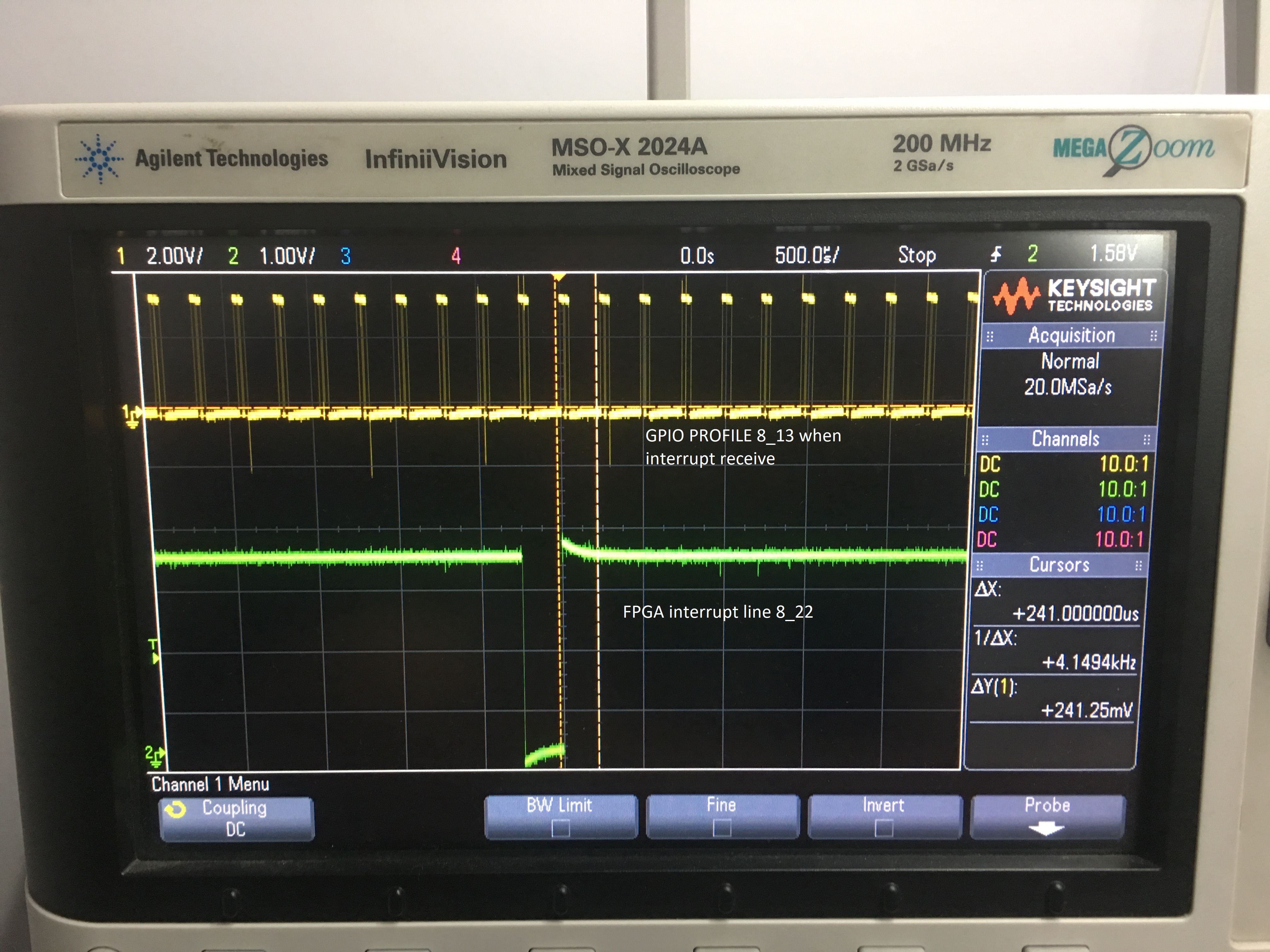
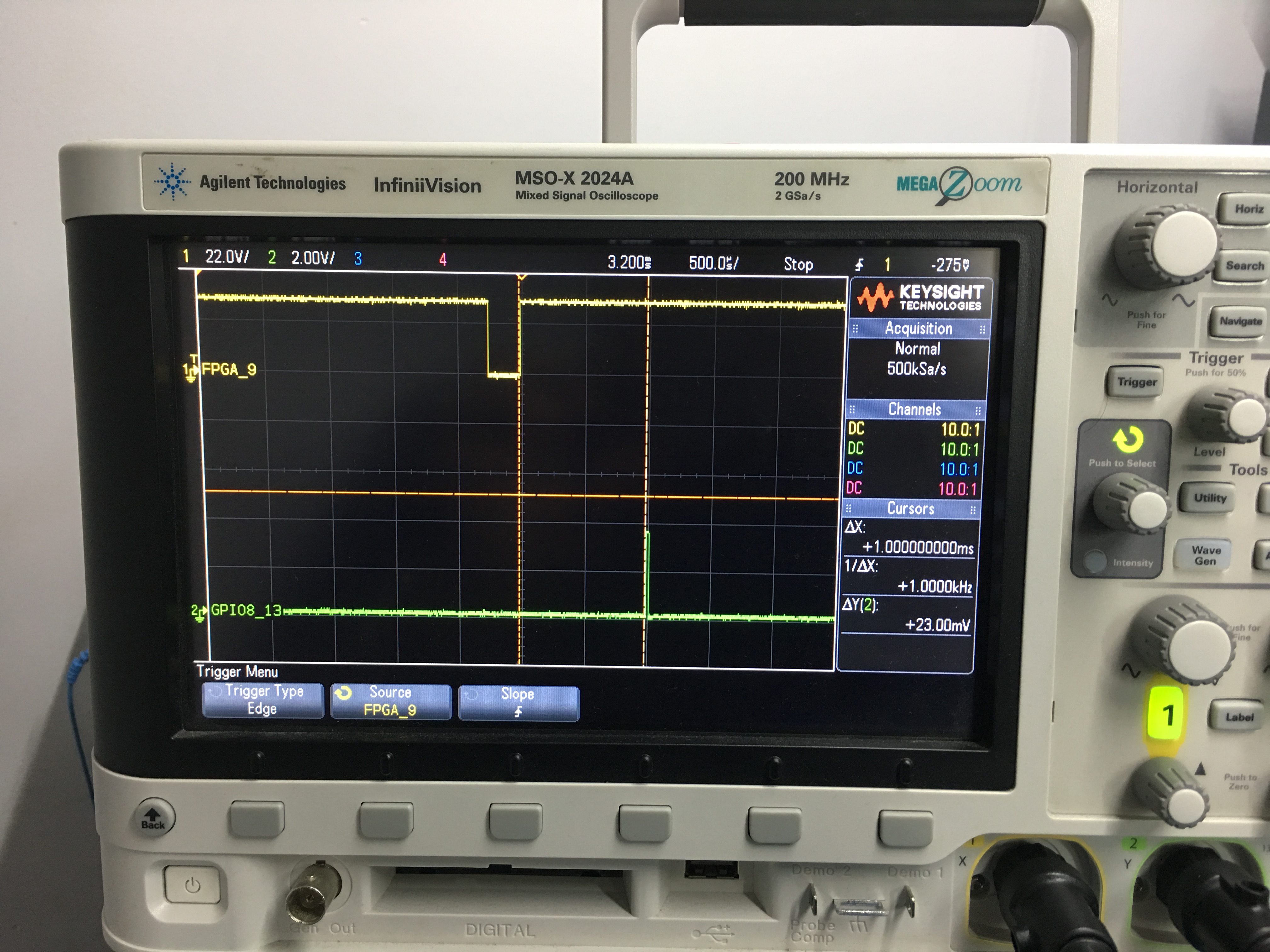
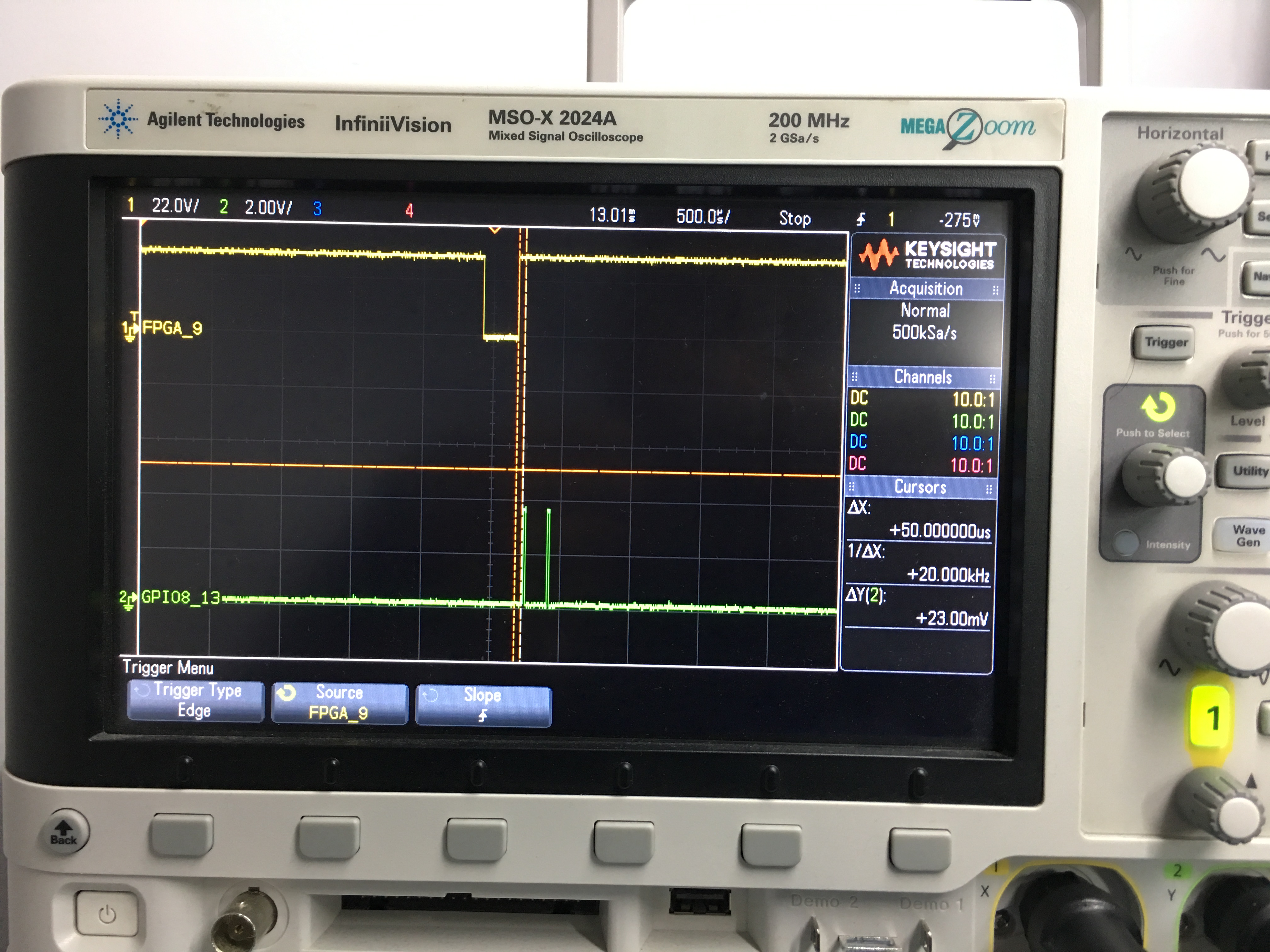
Can someone tell the place for finding event ids and interrupt numbers for creating HWI for GPIO 8-22.
Tool/software: TI C/C++ Compiler
Can someone tell the place for finding event ids and interrupt numbers for creating HWI for GPIO 8-22.