This thread has been locked.

If you have a related question, please click the "Ask a related question" button in the top right corner. The newly created question will be automatically linked to this question.

CCS/AM5728: I2C transmit issue

Part Number: AM5728

Tool/software: Code Composer Studio

Hi Team !

I'm struggling with an I2C issue, I've follow the Datasheet (from p.5740) and I've inspire my code from "*\ti\pdk_am57xx_1_0_14\packages\ti\csl\example\i2c\i2c_led_blink" (which should work ?)

My "SetupI2C" is exactly the same, I intend to use the I2C1, at 100kHz., with the slave address 0xAE.

My "transmitt" function must send only one byte and I've remove the delay, alla the rest is the same as the example.

BUT

It don't communicate...
I've monitored register : 

- I can see that "I2C_IRQSTATUS_RAW[7]" (AERR bit) keep staying up event after "FIFO clear", "fifo flush" or "I2CMasterIntClearEx"
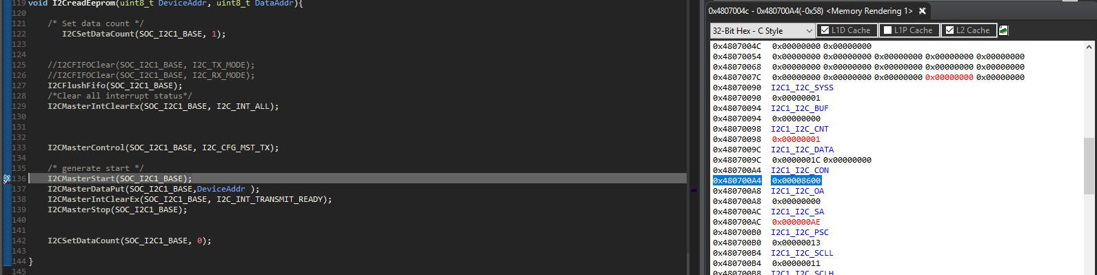
- About "I2C_CON" I never saw the stt bit climb to "1", the "mastercontrol" bring it to "8600" the the "MasterStart" bring it to "8200" but never to "8xx1".
So the start condition is never send BUT I cant osberve a byte "0x5C" just after the "MasterStart" command before the "dataPut" command
- Finally the "dataPut" command nerver write in "I2C_DATA", this register stay inchanged a along the code.


I don't understand why tis "0x5C" is send and why I cant send anything (volountary..).

Do you see anything I could have miss ?

thank's !

  • Hi Marine,

    Are you using TI EVM, or is this your own hardware platform?

    Have you tried the i2c_led_blink example OOB to see if it works?

    Do you see any activity on the I2C bus?

    Regards,
    Frank

  • Hi Frank,

    Thank you for answering.

    I'm using my own platform that's why I didn't tried the "i2c_led_blink" example but I assumed it worksso I've try to do the same as it does.


    Yes I do see something but I can't find why I see this and where do it come from...
    I've search in the code and I couldn't find any register which correspond to what I see on the bus.
    It seems that I can't write in "I2C_DATA" register even if I "clear" or "flush" the FIFO just before writing. I don't understant why I can't writte there.

    BEFOR the start command :


    I can see that the "I2C_CON" is Enabled and configured as Master in TX mode

    AFTER the start command, before the put command :

    I can see this (=0x5C) on the bus...

    Moreover

    The "I2C_CON" is now : Enabled and TX mode
    BUT
    the Master bit (I2C_CON[10](MST)) felt down and the Start condition bit (I2C_CON[1](STT)) didn't rise up.


    In addition we can't see on this pic but I2C_IRQSTATUS_RAW[7] (AERR) = 1 and I didn't find any way to shut it down.

    AFTER put command :

    Finally we can see that after the "put" command the "I2C_DATA" remains the same, so the "put" command didn't accessed the register and nothing happened on the bus.

    In addition we can't see on this pic but still I2C_IRQSTATUS_RAW[7] (AERR) = 1 and I didn't find any way to shut it down.

  • Hi Marine,

    Sorry for the delayed response. Are you still having this problem?

    Which core are you using to run the code? How are you handling Power, Clocks, and Reset? A GEL file?

    Just to make sure I understand: when you step over I2C_MasterStart(SOC_I2C1_BASE), you observe the spurious I2C bus activity? Can you step into this function? You should see this:

    void I2CMasterStart(uint32_t baseAddr)
    {
    HW_WR_FIELD32(baseAddr + I2C_CON, I2C_CON_STT, I2C_CON_STT_STT);
    }

    Step over the HW_WR_FIELD32() call and see if you observe the I2C bus activity when only executing this code.

    AERR should only be generated if a Data read access is performed while RX FIFO is empty or a Data write access is performed while TX FIFO is full. I see you're calling I2C_FlushFifo(), so I'm surprised to see the access error. You should be able to clear this by writing to the I2C_IRQSTATUS:AERR bit.

    The I2C_CON:STT bit should go from high (when written by I2CMasterStart() to low after the start condition is generated.

    Regards,
    Frank

  • Hi Frank,

    Yes I do still have the problem, I'm using the DSP1, I also use a gel file but I did as I was told, I did'nt really understood this part.


    I tried to follow step by step the methode  page 5744 of  the DataSheet, but nothing seem to work. the AERR rise whenever it want, and bus activity still happend on the return of "I2CMasterSart".

    I've look upstream in the code, it appears that the "AERR" bit rise up (red) at the enable of the I2C module in the "Setup" sequence, even if the FIFO is empty (orange) :


    So the problem must be before,

    - I've check the pinmux. The code does go through :
    pinmux.c ==> PinmuxI2cConfig() ==> case1

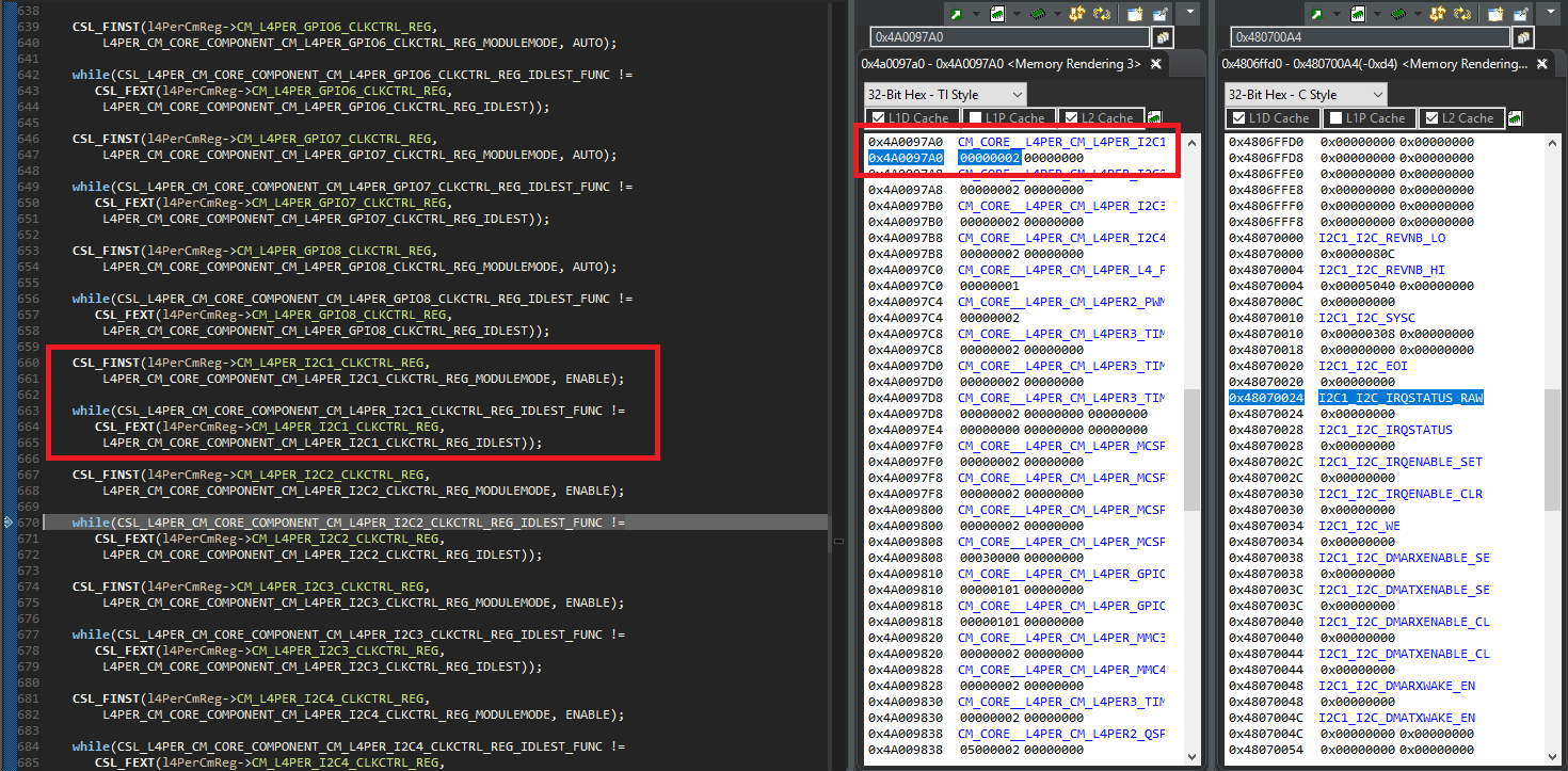
    - I've check the clock, which is active  : 

    I'm digging but I can't find anything.... Do you have an idea?

    Regards
    Marine

  • Hi Marine,

    I'm not sure why you're seeing this behavior.

    I notice your slave address is 8 bits, but you're configured for 7-bit addressing mode. Your scope capture seems to show the least-significant 7 bits of the 8-bit address being transmitted for a Read transaction.

    First bits transferred: 0 1 0 1 1 1 0, these are 7 LSBs of 0xAE.

    However, it looks like this is followed by:

    • R/W_ = 1 (Read)
    • ACK = 1 (NACK)

    Does your slave require an 8-bit address?

    Regards,
    Frank

  • Hi Frank !

    I do thank you for your answer !

    It was my problem, I didn't understood well the address management, now I can send the right frame and the device ACK to it.

    Thanks a lot !


    Marine.