This thread has been locked.

If you have a related question, please click the "Ask a related question" button in the top right corner. The newly created question will be automatically linked to this question.

[TDA4M] Single Camera Application Changes for New Sensor Support

Other Parts Discussed in Thread: DS90UB960-Q1, DS90UB935-Q1, DS90UB953-Q1, DS90UB913A-Q1, DS90UB933-Q1

Hi,

In continuation to the below thread for new camera support, 

http://e2e.ti.com/support/processors/f/791/t/854271.

I have following question:

The application "app_single_cam", is trying to enumerate the sensor list in app_init (app_single_cam_main.c) function by calling the function appEnumerateImageSensor (/vision_apps/utils/iss/src/app_iss.c)

How is this function appEnumerateImageSensor able to generate the list of sensors. ?

i found out that in function appEnumerateImageSensor it is calling the appRemoteServiceRun function. i.e 

status = appRemoteServiceRun(
APP_IPC_CPU_MCU2_1 ,
IMAGE_SENSOR_REMOTE_SERVICE_NAME,
IM_SENSOR_CMD_ENUMERATE,
(void*)g_cmdPrm,
CMD_PARAM_SIZE,
0
);

The array g_cmdPrm gets filled with the ascii values of the sensor names , whatever is defined using the macro 

#define SENSOR_SONY_IMX390_UB953_D3 "IMX390-UB953_D3"
#define SENSOR_ONSEMI_AR0233_UB953_MARS "AR0233-UB953_MARS"
#define SENSOR_ONSEMI_AR0820_UB953_LI "AR0820-UB953_LI"
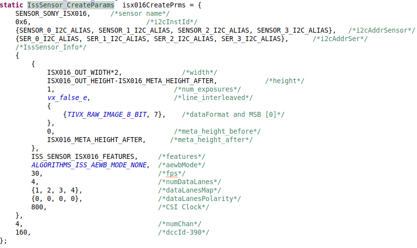
#define SENSOR_SONY_ISX016 "ISX016-UB913"   //Added by me

My problem is that even if i add my custom name, it is only picking first 3 names and enumerating the sensor list. I am unable to trace the location of the code from where i can make the code to pick my sensor.

Note: I have made the application changes as suggested by Mr. Mayank Mangla over email.

Regards,

Anshuman


  • Sensors are registered with the framework during IssSensor_Init() function. Init function of all individual drivers must be called from this function. For e.g. the current implementation is

        status |= IssSensor_IMX390_Init();
        status |= IssSensor_AR0233_Init();
        status |= IssSensor_AR0820_Init();

    You need to create something like IssSensor_ISX016_Init() and add the call here. In IssSensor_ISX016_Init() you will need to call IssSensor_Register with a device handle. Device handle contains all the sensor parameters and callback functions.

  • Hi Mayank,

    I did create my function named IssSensor_ISX016_Init(). Even i commented the init calls of the other sensor drivers.

    Even then the single camera application was picking the imx390 sensor during sensor selection.

    But what i am unable to understand is how the application calls the function IssSensor_Init() .

    I am unable to figure how application enters into this function.

    Please throw some light on that.

    Regards,

    Anshuman

  • How are you running the single cam app? Can you please share the exact command?

  • I am directly calling the ./vx_app_single_cam.out

    In the c file of the application single_cam_main.c

    I have commented the parsing cfg file call and the user interactive part of the code.

  • I am unable to predict the application behavior if you have local changes. Typically when interactive mode is ON, the app presents the list of all enumerated sensors to the user and asks for a selection (a/b/c/d).

  • Hi Mayank,

    In accordance with the interactive mode and the config file based option,

    I tried this also: i modified the app_single_cam.cfg in SD card to add my sensor name.

    Then i ran the following command:

    ./run_app_single_cam.sh

    Even then on running i am not getting the sensor name on the list displayed on console.

    My doubt is that how is the application accessing the new sensor name.

  • Please try running the application without any arguments. It will default to interactive mode.

    If you still don't see ISX016 in the list, it means that the the sensor registration failed. Please add detailed logs to ISX016_init function and share the logs.

  • Okay. I will do the same and share the logs.

  • Hi Mayank,

    Thanks for your suggestion to debug the init function. Now i am able to find my sensor name and ISX016_init is getting successful.

    Moving forward, I am getting error in create graph, I am trying to debug the same. 

    The problem i am facing now is that my graph contains only 2 nodes : capture ---> display

    obj->capture_node = tivxCaptureNode(obj->graph, capture_config, obj->cap_frames[0]);
    xReleaseUserDataObject(&capture_config);
    vxSetNodeTarget(obj->capture_node, VX_TARGET_STRING, TIVX_TARGET_CAPTURE1);
    obj->raw = (tivx_raw_image)vxGetObjectArrayItem(obj->cap_frames[0], 0);
    tivxReleaseRawImage(&raw_image);

    Capture node creation is successful and while creating the display node it gives an error:

    if(NULL == display_image)
    {
    printf("Error : Display input is uninitialized \n");
    return VX_FAILURE;
    }

    obj->displayNode = tivxDisplayNode(obj->graph, obj->display_param_obj, display_image);
    vxSetNodeTarget(obj->displayNode, VX_TARGET_STRING, TIVX_TARGET_DISPLAY1);

    I found that display_image is of type vx_image and obj->raw is of type tivx_raw_image. I need to map these data objects so that data can be passed to display node.

    Simply by doing  "display_image = (vx_image)obj->raw" before display node creation is throwing error. 

    I want to know how to map these two objects. I even tried using vxMapImagePatch and tivxMapRawImagePatch to fetch the data pointer, still that did not work.

    Please suggest.

    Regards,

    Anshuman

  • Hi Mayank,

    In addition to above experiment done my me, i found a post mentioning  changes w.r.t capture and display node 

    https://e2e.ti.com/support/j721e/f/1026/t/854328

    Lucas is suggesting "The output from the capture node in the single camera application has an output called cap_frames.  Presently, this is being given as an input to VISS.  However, you can simply give this as an input to display if you are wanting it to be just a capture -> display graph."


    So i tried to modify the display node as follows:

            obj->displayNode = tivxDisplayNode(obj->graph, obj->display_param_obj, (vx_image)obj->cap_frames[0]);

    then i am getting the error:

    139.004730 s: VX_ZONE_ERROR:[vxSetParameterByIndex:228] Supplied value was not actually a reference
    139.004736 s: VX_ZONE_ERROR:[vxSetParameterByIndex:307] Specified: parameter[1] type:00000000 => 0x682f08
    139.004741 s: VX_ZONE_ERROR:[vxSetParameterByIndex:311] Required: parameter[1] dir:0 type:0000080f

  • Anshuman,

    Yes, you will need those changes to be able to display YUV422 cleanly. But let's first get the data capture working. 

    I suggest not to mix the threads. If you want help on display node, please create another thread.

    Regards,

    Mayank

  • Hi Mayank,

    With reference to camera interfacing, 
    I have been able to create the graph with two nodes Capture and Display. Create and Verify Graph is successful and my code is going into run graph state.
    My camera is directly connected to sensor fusion board (Cam0 port) like this:
                Sensor Fusion Board    <-------->    Camera with ISP
                        Deser(UB960)                              Ser(UB913)
    I have made the serializer configuration changes in the isx016_serdes_config.h file. I haven't touched the deserializer configuration settings.
    In the app_run_graph function of the single camera application my code flow is as follows:
       1 --> Sensor start command is sent (appStartImageSensor fn. call)
       2 --> enqueue buffer for pipeup
       3 -->  enqueue a buffer to trigger graph scheduling 
       4 --> trigger again since display holds on to a buffer
       5 --> wait for graph instances to complete
       6 --> call vxWaitGraph
       7 --> Dequeue buf for pipe down
       8 --> appStopImageSensor fn. call
    I have attached the console log wherein i have few detailed prints on some functions. 
    My code reaches to the point of appStartImageSensor and is stuck in graph instance to complete (step 4) 
    I am unable to figure out what could have gone wrong.
     I am attaching my app_single_cam_main.c file and the uart logs
    0741.files.zipPlease suggest.

    Regards,

    Anshuman

  • Anshuman,

    This thread has deviated from the original topic (new sensor support). Please start a new thread so that it can be assigned to a display node expert.

    Regards,

    Mayank

  • Hi Mayank,

    I am unable to receive the data after capture node. This is what i am trying to convey.

    I have modified the graph as suggested by you.

    My main motive is to get the new sensor up and receive data.

    In accordance with that, i am unable to receive data after appStartImageSensor fn. Call.

    I want support for the same on how to debug whether i have done all the steps and how to receive data from the sensor.

    Let me if i am able to clarify.

  • To receive the data,

    1. Please ensure that sensor, serializer and deserializer settings are correct. All these devices have status registers which you can check through I2C reads. Please refer to the datasheet of the individual devices

    2. Please pay special attention to StreamOn function in the sensor file. This is where the streaming should be enabled (from sensor and deserializer). In the initial config, streaming must NOT be started.

  • Hi Mayank,

    I am able to read the register status of Serializer and there are no errors on serializer side.

    As suggested by you, Now i will try to read the status of the deserializer registers to check if i am able to receive anything from camera.

    Regards,

    Anshuman

  • Hi Mayank, As suggested by you, following are the values received at the deserializer pins.

    Deserializer Registers Address Value
    DEVICE_STS Register 0x04 0xD0
    FWD_STS Register  0x22 0x00
    CSI_STS Register 0x35 0x01
    RX_PORT_STS1 Register 0x4D 0xC0
    CSI0_FRAME_COUNT_HI Register 0x90 0x00
    CSI0_FRAME_COUNT_LO Register 0x91 0x1C


    Register Address 0x91 When read, this register returns the value of bits [7:0] of the 16-bit counter csi1_frame_count.

    So i suppose, data is being received, is my understanding correct ?

    If above assumption is correct, then please guide me ahead on where to look for the problem.

    Regards,

    Anshuman

  • Please try 8b RAW format with MSB = 7, as we discussed on the call.

  • Hi Mayank,

    I did try that option, but the create graph failed, i am trying to understand the cause behind it. I will keep you posted once i debug that.

  • Hi Mayank,

    Since, We are unable to find any application note for FPD-Link III I 2C Initialization between UB960-UB913 pair,
    We need TI's help to verify the deserializer settings done for receiving the data from Serializer.
    As Per my understanding we have the following setup and we need to establish the link between UB960 (Deser) <----> UB913 (Ser)
     
     
    The DS90UB960-Q1 supports two main operating modes:
        • CSI-2 Mode (DS90UB953-Q1 / DS90UB935-Q1 compatible)
        • RAW Mode (DS90UB933-Q1 / DS90UB913A-Q1 compatible)
    Since UB913 does not support CSI-2 Mode, We are selecting the RAW 10 bit mode because in RAW mode, the DS90UB960-Q1 receives RAW8, RAW10, or RAW12 data from DS90UB913-Q1 serializer.
    The data is then translated into a RAW8, RAW10, or RAW12 CSI-2 video stream for
    forwarding on one of the CSI-2 transmit ports.
    So we need to set the Deserializer in that mode. 
    Accordingly we have programmed the following registers of the Deserializer. I am showing few important one's 
     
     
    Similarly on the Serializer side , we programmed the following registers:
     
     
    Since, We are unable to find any application note for FPD-Link III I 2C Initialization between UB960-UB913 pair,
    We need TI to verify the deserializer settings done for receiving the data from Serializer.
    We are able to read all the register values from the Deserializer and serializer that can help in debugging. I am attaching the logs for the same.
    UB913 Serializer Register
    
    [MCU2_1]  I2C: Reading 0x35 registers starting from REG 0x00 of device 0x74 ... !!!
    [MCU2_1]     88.368981 s:  I2C: 0x0 = 0xb0
    [MCU2_1]     88.369206 s:  I2C: 0x1 = 0x30
    [MCU2_1]     88.369421 s:  I2C: 0x2 = 0x20
    [MCU2_1]     88.369644 s:  I2C: 0x3 = 0xc5
    [MCU2_1]     88.369867 s:  I2C: 0x4 = 0x80
    [MCU2_1]     88.370081 s:  I2C: 0x5 = 0x14
    [MCU2_1]     88.370299 s:  I2C: 0x6 = 0x7a
    [MCU2_1]     88.370514 s:  I2C: 0x7 = 0x0
    [MCU2_1]     88.370745 s:  I2C: 0x8 = 0x0
    [MCU2_1]     88.370958 s:  I2C: 0x9 = 0x0
    [MCU2_1]     88.371175 s:  I2C: 0xa = 0x0
    [MCU2_1]     88.371390 s:  I2C: 0xb = 0x0
    [MCU2_1]     88.371608 s:  I2C: 0xc = 0x15
    [MCU2_1]     88.371824 s:  I2C: 0xd = 0x55
    [MCU2_1]     88.372038 s:  I2C: 0xe = 0x35
    [MCU2_1]     88.372253 s:  I2C: 0xf = 0x0
    [MCU2_1]     88.372471 s:  I2C: 0x10 = 0x17
    [MCU2_1]     88.372687 s:  I2C: 0x11 = 0x32
    [MCU2_1]     88.372902 s:  I2C: 0x12 = 0x32
    [MCU2_1]     88.373118 s:  I2C: 0x13 = 0x0
    [MCU2_1]     88.373334 s:  I2C: 0x14 = 0x0
    [MCU2_1]     88.373555 s:  I2C: 0x15 = 0x31
    [MCU2_1]     88.373779 s:  I2C: 0x16 = 0x80
    [MCU2_1]     88.373993 s:  I2C: 0x17 = 0x0
    [MCU2_1]     88.374212 s:  I2C: 0x18 = 0x0
    [MCU2_1]     88.374425 s:  I2C: 0x19 = 0x0
    [MCU2_1]     88.374646 s:  I2C: 0x1a = 0x0
    [MCU2_1]     88.374869 s:  I2C: 0x1b = 0x0
    [MCU2_1]     88.375087 s:  I2C: 0x1c = 0x0
    [MCU2_1]     88.375301 s:  I2C: 0x1d = 0xa0
    [MCU2_1]     88.375518 s:  I2C: 0x1e = 0xfe
    [MCU2_1]     88.375749 s:  I2C: 0x1f = 0x0
    [MCU2_1]     88.375962 s:  I2C: 0x20 = 0xe
    [MCU2_1]     88.376179 s:  I2C: 0x21 = 0x1c
    [MCU2_1]     88.376393 s:  I2C: 0x22 = 0x29
    [MCU2_1]     88.376619 s:  I2C: 0x23 = 0x0
    [MCU2_1]     88.376839 s:  I2C: 0x24 = 0x0
    [MCU2_1]     88.377054 s:  I2C: 0x25 = 0x0
    [MCU2_1]     88.377270 s:  I2C: 0x26 = 0x0
    [MCU2_1]     88.377504 s:  I2C: 0x27 = 0x0
    [MCU2_1]     88.377741 s:  I2C: 0x28 = 0x25
    [MCU2_1]     88.377967 s:  I2C: 0x29 = 0x6
    [MCU2_1]     88.378183 s:  I2C: 0x2a = 0x0
    [MCU2_1]     88.378399 s:  I2C: 0x2b = 0x0
    [MCU2_1]     88.378616 s:  I2C: 0x2c = 0x0
    [MCU2_1]     88.378830 s:  I2C: 0x2d = 0x0
    [MCU2_1]     88.379045 s:  I2C: 0x2e = 0x0
    [MCU2_1]     88.379262 s:  I2C: 0x2f = 0x0
    [MCU2_1]     88.379479 s:  I2C: 0x30 = 0x0
    [MCU2_1]     88.379696 s:  I2C: 0x31 = 0x0
    [MCU2_1]     88.379911 s:  I2C: 0x32 = 0x0
    [MCU2_1]     88.380126 s:  I2C: 0x33 = 0xfe
    [MCU2_1]     88.380342 s:  I2C: 0x34 = 0x80
    [MCU2_1]     88.380366 s: 
    [MCU2_1]     88.380401 s: 
    UB960 DeSerializer Register
    
    [MCU2_1]  I2C: Reading 0xfe registers starting from REG 0x00 of device 0x3d ... !!!
    [MCU2_1]     88.380569 s:  I2C: 0x0 = 0x7a
    [MCU2_1]     88.380722 s:  I2C: 0x1 = 0x0
    [MCU2_1]     88.380872 s:  I2C: 0x2 = 0x1e
    [MCU2_1]     88.381023 s:  I2C: 0x3 = 0x40
    [MCU2_1]     88.381171 s:  I2C: 0x4 = 0xd0
    [MCU2_1]     88.381317 s:  I2C: 0x5 = 0x1
    [MCU2_1]     88.381466 s:  I2C: 0x6 = 0x0
    [MCU2_1]     88.381616 s:  I2C: 0x7 = 0xfe
    [MCU2_1]     88.381766 s:  I2C: 0x8 = 0x1c
    [MCU2_1]     88.381914 s:  I2C: 0x9 = 0x10
    [MCU2_1]     88.382059 s:  I2C: 0xa = 0x7a
    [MCU2_1]     88.382208 s:  I2C: 0xb = 0x7a
    [MCU2_1]     88.382354 s:  I2C: 0xc = 0xf
    [MCU2_1]     88.382501 s:  I2C: 0xd = 0xb9
    [MCU2_1]     88.382658 s:  I2C: 0xe = 0x10
    [MCU2_1]     88.382810 s:  I2C: 0xf = 0xff
    [MCU2_1]     88.382962 s:  I2C: 0x10 = 0x0
    [MCU2_1]     88.383111 s:  I2C: 0x11 = 0x0
    [MCU2_1]     88.383258 s:  I2C: 0x12 = 0x0
    [MCU2_1]     88.383406 s:  I2C: 0x13 = 0x0
    [MCU2_1]     88.383558 s:  I2C: 0x14 = 0x0
    [MCU2_1]     88.383712 s:  I2C: 0x15 = 0x0
    [MCU2_1]     88.383861 s:  I2C: 0x16 = 0x0
    [MCU2_1]     88.384009 s:  I2C: 0x17 = 0x0
    [MCU2_1]     88.384156 s:  I2C: 0x18 = 0x0
    [MCU2_1]     88.384303 s:  I2C: 0x19 = 0x0
    [MCU2_1]     88.384450 s:  I2C: 0x1a = 0x0
    [MCU2_1]     88.384611 s:  I2C: 0x1b = 0x0
    [MCU2_1]     88.384765 s:  I2C: 0x1c = 0x0
    [MCU2_1]     88.384915 s:  I2C: 0x1d = 0xff
    [MCU2_1]     88.385062 s:  I2C: 0x1e = 0xff
    [MCU2_1]     88.385212 s:  I2C: 0x1f = 0x0
    [MCU2_1]     88.385361 s:  I2C: 0x20 = 0x0
    [MCU2_1]     88.385508 s:  I2C: 0x21 = 0x3
    [MCU2_1]     88.385667 s:  I2C: 0x22 = 0x0
    [MCU2_1]     88.385817 s:  I2C: 0x23 = 0x0
    [MCU2_1]     88.385963 s:  I2C: 0x24 = 0x0
    [MCU2_1]     88.386110 s:  I2C: 0x25 = 0x0
    [MCU2_1]     88.386257 s:  I2C: 0x26 = 0x0
    [MCU2_1]     88.386404 s:  I2C: 0x27 = 0x0
    [MCU2_1]     88.386554 s:  I2C: 0x28 = 0x0
    [MCU2_1]     88.386704 s:  I2C: 0x29 = 0x0
    [MCU2_1]     88.386855 s:  I2C: 0x2a = 0x0
    [MCU2_1]     88.387003 s:  I2C: 0x2b = 0x0
    [MCU2_1]     88.387150 s:  I2C: 0x2c = 0x0
    [MCU2_1]     88.387298 s:  I2C: 0x2d = 0x0
    [MCU2_1]     88.387444 s:  I2C: 0x2e = 0x0
    [MCU2_1]     88.387602 s:  I2C: 0x2f = 0x0
    [MCU2_1]     88.387756 s:  I2C: 0x30 = 0x0
    [MCU2_1]     88.387905 s:  I2C: 0x31 = 0x0
    [MCU2_1]     88.388052 s:  I2C: 0x32 = 0x1
    [MCU2_1]     88.388200 s:  I2C: 0x33 = 0x3
    [MCU2_1]     88.388348 s:  I2C: 0x34 = 0x0
    [MCU2_1]     88.388493 s:  I2C: 0x35 = 0x1
    [MCU2_1]     88.388642 s:  I2C: 0x36 = 0x0
    [MCU2_1]     88.388793 s:  I2C: 0x37 = 0x3
    [MCU2_1]     88.388942 s:  I2C: 0x38 = 0x0
    [MCU2_1]     88.389090 s:  I2C: 0x39 = 0x0
    [MCU2_1]     88.389236 s:  I2C: 0x3a = 0x0
    [MCU2_1]     88.389382 s:  I2C: 0x3b = 0x0
    [MCU2_1]     88.389541 s:  I2C: 0x3c = 0x0
    [MCU2_1]     88.389694 s:  I2C: 0x3d = 0x0
    [MCU2_1]     88.389844 s:  I2C: 0x3e = 0x0
    [MCU2_1]     88.389994 s:  I2C: 0x3f = 0x0
    [MCU2_1]     88.390142 s:  I2C: 0x40 = 0x0
    [MCU2_1]     88.390291 s:  I2C: 0x41 = 0xa9
    [MCU2_1]     88.390440 s:  I2C: 0x42 = 0x71
    [MCU2_1]     88.390590 s:  I2C: 0x43 = 0x1
    [MCU2_1]     88.390743 s:  I2C: 0x44 = 0x0
    [MCU2_1]     88.390890 s:  I2C: 0x45 = 0x0
    [MCU2_1]     88.391038 s:  I2C: 0x46 = 0x20
    [MCU2_1]     88.391186 s:  I2C: 0x47 = 0x0
    [MCU2_1]     88.391332 s:  I2C: 0x48 = 0x0
    [MCU2_1]     88.391479 s:  I2C: 0x49 = 0x0
    [MCU2_1]     88.391632 s:  I2C: 0x4a = 0x0
    [MCU2_1]     88.391787 s:  I2C: 0x4b = 0x12
    [MCU2_1]     88.391938 s:  I2C: 0x4c = 0x38
    [MCU2_1]     88.392085 s:  I2C: 0x4d = 0xc0
    [MCU2_1]     88.392235 s:  I2C: 0x4e = 0x2
    [MCU2_1]     88.392383 s:  I2C: 0x4f = 0x0
    [MCU2_1]     88.392544 s:  I2C: 0x50 = 0x0
    [MCU2_1]     88.392694 s:  I2C: 0x51 = 0x0
    [MCU2_1]     88.392842 s:  I2C: 0x52 = 0x0
    [MCU2_1]     88.392988 s:  I2C: 0x53 = 0x0
    [MCU2_1]     88.393138 s:  I2C: 0x54 = 0x0
    [MCU2_1]     88.393286 s:  I2C: 0x55 = 0x0
    [MCU2_1]     88.393432 s:  I2C: 0x56 = 0x0
    [MCU2_1]     88.393583 s:  I2C: 0x57 = 0x0
    [MCU2_1]     88.393736 s:  I2C: 0x58 = 0x58
    [MCU2_1]     88.393887 s:  I2C: 0x59 = 0x0
    [MCU2_1]     88.394051 s:  I2C: 0x5a = 0x0
    [MCU2_1]     88.394209 s:  I2C: 0x5b = 0x0
    [MCU2_1]     88.394363 s:  I2C: 0x5c = 0x0
    [MCU2_1]     88.394513 s:  I2C: 0x5d = 0xb0
    [MCU2_1]     88.394677 s:  I2C: 0x5e = 0xe0
    [MCU2_1]     88.394830 s:  I2C: 0x5f = 0x0
    [MCU2_1]     88.394981 s:  I2C: 0x60 = 0x0
    [MCU2_1]     88.395128 s:  I2C: 0x61 = 0x0
    [MCU2_1]     88.395277 s:  I2C: 0x62 = 0x0
    [MCU2_1]     88.395423 s:  I2C: 0x63 = 0x0
    [MCU2_1]     88.395572 s:  I2C: 0x64 = 0x0
    [MCU2_1]     88.395724 s:  I2C: 0x65 = 0xf4
    [MCU2_1]     88.395873 s:  I2C: 0x66 = 0x8c
    [MCU2_1]     88.396020 s:  I2C: 0x67 = 0x0
    [MCU2_1]     88.396170 s:  I2C: 0x68 = 0x0
    [MCU2_1]     88.396315 s:  I2C: 0x69 = 0x0
    [MCU2_1]     88.396466 s:  I2C: 0x6a = 0x0
    [MCU2_1]     88.396615 s:  I2C: 0x6b = 0x0
    [MCU2_1]     88.396766 s:  I2C: 0x6c = 0x0
    [MCU2_1]     88.396915 s:  I2C: 0x6d = 0x7f
    [MCU2_1]     88.397064 s:  I2C: 0x6e = 0x98
    [MCU2_1]     88.397213 s:  I2C: 0x6f = 0x88
    [MCU2_1]     88.397359 s:  I2C: 0x70 = 0xde
    [MCU2_1]     88.397508 s:  I2C: 0x71 = 0xec
    [MCU2_1]     88.397668 s:  I2C: 0x72 = 0xff
    [MCU2_1]     88.397819 s:  I2C: 0x73 = 0x0
    [MCU2_1]     88.397967 s:  I2C: 0x74 = 0x0
    [MCU2_1]     88.398114 s:  I2C: 0x75 = 0x0
    [MCU2_1]     88.398265 s:  I2C: 0x76 = 0x0
    [MCU2_1]     88.398411 s:  I2C: 0x77 = 0xc5
    [MCU2_1]     88.398563 s:  I2C: 0x78 = 0x0
    [MCU2_1]     88.398713 s:  I2C: 0x79 = 0x1
    [MCU2_1]     88.398861 s:  I2C: 0x7a = 0x0
    [MCU2_1]     88.399009 s:  I2C: 0x7b = 0x0
    [MCU2_1]     88.399156 s:  I2C: 0x7c = 0x81
    [MCU2_1]     88.399304 s:  I2C: 0x7d = 0x0
    [MCU2_1]     88.399452 s:  I2C: 0x7e = 0x0
    [MCU2_1]     88.399611 s:  I2C: 0x7f = 0x0
    [MCU2_1]     88.399761 s:  I2C: 0x80 = 0x0
    [MCU2_1]     88.399907 s:  I2C: 0x81 = 0x0
    [MCU2_1]     88.400052 s:  I2C: 0x82 = 0x0
    [MCU2_1]     88.400199 s:  I2C: 0x83 = 0x0
    [MCU2_1]     88.400347 s:  I2C: 0x84 = 0x0
    [MCU2_1]     88.400494 s:  I2C: 0x85 = 0x0
    [MCU2_1]     88.400645 s:  I2C: 0x86 = 0x0
    [MCU2_1]     88.400796 s:  I2C: 0x87 = 0x0
    [MCU2_1]     88.400943 s:  I2C: 0x88 = 0x0
    [MCU2_1]     88.401091 s:  I2C: 0x89 = 0x0
    [MCU2_1]     88.401239 s:  I2C: 0x8a = 0x0
    [MCU2_1]     88.401386 s:  I2C: 0x8b = 0x0
    [MCU2_1]     88.401543 s:  I2C: 0x8c = 0x0
    [MCU2_1]     88.401695 s:  I2C: 0x8d = 0x0
    [MCU2_1]     88.401843 s:  I2C: 0x8e = 0x0
    [MCU2_1]     88.401991 s:  I2C: 0x8f = 0x0
    [MCU2_1]     88.402139 s:  I2C: 0x90 = 0x0
    [MCU2_1]     88.402286 s:  I2C: 0x91 = 0x1c
    [MCU2_1]     88.402435 s:  I2C: 0x92 = 0x0
    [MCU2_1]     88.402587 s:  I2C: 0x93 = 0x1
    [MCU2_1]     88.402739 s:  I2C: 0x94 = 0x0
    [MCU2_1]     88.402891 s:  I2C: 0x95 = 0x0
    [MCU2_1]     88.403040 s:  I2C: 0x96 = 0x0
    [MCU2_1]     88.403187 s:  I2C: 0x97 = 0x0
    [MCU2_1]     88.403334 s:  I2C: 0x98 = 0x0
    [MCU2_1]     88.403481 s:  I2C: 0x99 = 0x0
    [MCU2_1]     88.403632 s:  I2C: 0x9a = 0x0
    [MCU2_1]     88.403783 s:  I2C: 0x9b = 0x0
    [MCU2_1]     88.403931 s:  I2C: 0x9c = 0x0
    [MCU2_1]     88.404078 s:  I2C: 0x9d = 0x0
    [MCU2_1]     88.404226 s:  I2C: 0x9e = 0x0
    [MCU2_1]     88.404372 s:  I2C: 0x9f = 0x0
    [MCU2_1]     88.404522 s:  I2C: 0xa0 = 0x0
    [MCU2_1]     88.404682 s:  I2C: 0xa1 = 0x0
    [MCU2_1]     88.404832 s:  I2C: 0xa2 = 0x0
    [MCU2_1]     88.404978 s:  I2C: 0xa3 = 0x0
    [MCU2_1]     88.405126 s:  I2C: 0xa4 = 0x0
    [MCU2_1]     88.405271 s:  I2C: 0xa5 = 0x1d
    [MCU2_1]     88.405418 s:  I2C: 0xa6 = 0x0
    [MCU2_1]     88.405569 s:  I2C: 0xa7 = 0x0
    [MCU2_1]     88.405719 s:  I2C: 0xa8 = 0x0
    [MCU2_1]     88.405869 s:  I2C: 0xa9 = 0x0
    [MCU2_1]     88.406016 s:  I2C: 0xaa = 0x0
    [MCU2_1]     88.406166 s:  I2C: 0xab = 0x0
    [MCU2_1]     88.406312 s:  I2C: 0xac = 0x0
    [MCU2_1]     88.406460 s:  I2C: 0xad = 0x0
    [MCU2_1]     88.406612 s:  I2C: 0xae = 0x0
    [MCU2_1]     88.406761 s:  I2C: 0xaf = 0x0
    [MCU2_1]     88.406908 s:  I2C: 0xb0 = 0x1c
    [MCU2_1]     88.407056 s:  I2C: 0xb1 = 0x13
    [MCU2_1]     88.407204 s:  I2C: 0xb2 = 0x1f
    [MCU2_1]     88.407352 s:  I2C: 0xb3 = 0x8
    [MCU2_1]     88.407499 s:  I2C: 0xb4 = 0x25
    [MCU2_1]     88.407651 s:  I2C: 0xb5 = 0x0
    [MCU2_1]     88.407805 s:  I2C: 0xb6 = 0x18
    [MCU2_1]     88.407953 s:  I2C: 0xb7 = 0x0
    [MCU2_1]     88.408101 s:  I2C: 0xb8 = 0xfc
    [MCU2_1]     88.408249 s:  I2C: 0xb9 = 0x33
    [MCU2_1]     88.408398 s:  I2C: 0xba = 0x83
    [MCU2_1]     88.408548 s:  I2C: 0xbb = 0x74
    [MCU2_1]     88.408700 s:  I2C: 0xbc = 0x80
    [MCU2_1]     88.408852 s:  I2C: 0xbd = 0x0
    [MCU2_1]     88.409001 s:  I2C: 0xbe = 0x0
    [MCU2_1]     88.409151 s:  I2C: 0xbf = 0x0
    [MCU2_1]     88.409300 s:  I2C: 0xc0 = 0x0
    [MCU2_1]     88.409445 s:  I2C: 0xc1 = 0x0
    [MCU2_1]     88.409601 s:  I2C: 0xc2 = 0x0
    [MCU2_1]     88.409754 s:  I2C: 0xc3 = 0x0
    [MCU2_1]     88.409906 s:  I2C: 0xc4 = 0x0
    [MCU2_1]     88.410055 s:  I2C: 0xc5 = 0x0
    [MCU2_1]     88.410203 s:  I2C: 0xc6 = 0x0
    [MCU2_1]     88.410348 s:  I2C: 0xc7 = 0x0
    [MCU2_1]     88.410496 s:  I2C: 0xc8 = 0x0
    [MCU2_1]     88.410653 s:  I2C: 0xc9 = 0x0
    [MCU2_1]     88.410810 s:  I2C: 0xca = 0x0
    [MCU2_1]     88.410962 s:  I2C: 0xcb = 0x0
    [MCU2_1]     88.411108 s:  I2C: 0xcc = 0x0
    [MCU2_1]     88.411257 s:  I2C: 0xcd = 0x0
    [MCU2_1]     88.411405 s:  I2C: 0xce = 0x0
    [MCU2_1]     88.411558 s:  I2C: 0xcf = 0x0
    [MCU2_1]     88.411711 s:  I2C: 0xd0 = 0x0
    [MCU2_1]     88.411860 s:  I2C: 0xd1 = 0x43
    [MCU2_1]     88.412008 s:  I2C: 0xd2 = 0x94
    [MCU2_1]     88.412157 s:  I2C: 0xd3 = 0xf
    [MCU2_1]     88.412304 s:  I2C: 0xd4 = 0x60
    [MCU2_1]     88.412454 s:  I2C: 0xd5 = 0xf2
    [MCU2_1]     88.412612 s:  I2C: 0xd6 = 0x0
    [MCU2_1]     88.412764 s:  I2C: 0xd7 = 0x3
    [MCU2_1]     88.412913 s:  I2C: 0xd8 = 0x0
    [MCU2_1]     88.413060 s:  I2C: 0xd9 = 0x0
    [MCU2_1]     88.413209 s:  I2C: 0xda = 0x0
    [MCU2_1]     88.413357 s:  I2C: 0xdb = 0x0
    [MCU2_1]     88.413505 s:  I2C: 0xdc = 0x0
    [MCU2_1]     88.413664 s:  I2C: 0xdd = 0x0
    [MCU2_1]     88.413816 s:  I2C: 0xde = 0x0
    [MCU2_1]     88.413965 s:  I2C: 0xdf = 0x0
    [MCU2_1]     88.414115 s:  I2C: 0xe0 = 0x0
    [MCU2_1]     88.414262 s:  I2C: 0xe1 = 0x0
    [MCU2_1]     88.414409 s:  I2C: 0xe2 = 0x0
    [MCU2_1]     88.414563 s:  I2C: 0xe3 = 0x0
    [MCU2_1]     88.414715 s:  I2C: 0xe4 = 0x0
    [MCU2_1]     88.414863 s:  I2C: 0xe5 = 0x0
    [MCU2_1]     88.415012 s:  I2C: 0xe6 = 0x0
    [MCU2_1]     88.415158 s:  I2C: 0xe7 = 0x0
    [MCU2_1]     88.415306 s:  I2C: 0xe8 = 0x0
    [MCU2_1]     88.415454 s:  I2C: 0xe9 = 0x0
    [MCU2_1]     88.415609 s:  I2C: 0xea = 0x0
    [MCU2_1]     88.415758 s:  I2C: 0xeb = 0x0
    [MCU2_1]     88.415908 s:  I2C: 0xec = 0x0
    [MCU2_1]     88.416055 s:  I2C: 0xed = 0x0
    [MCU2_1]     88.416202 s:  I2C: 0xee = 0x0
    [MCU2_1]     88.416348 s:  I2C: 0xef = 0x0
    [MCU2_1]     88.416497 s:  I2C: 0xf0 = 0x5f
    [MCU2_1]     88.416648 s:  I2C: 0xf1 = 0x55
    [MCU2_1]     88.416798 s:  I2C: 0xf2 = 0x42
    [MCU2_1]     88.416947 s:  I2C: 0xf3 = 0x39
    [MCU2_1]     88.417093 s:  I2C: 0xf4 = 0x36
    [MCU2_1]     88.417243 s:  I2C: 0xf5 = 0x30
    [MCU2_1]     88.417390 s:  I2C: 0xf6 = 0x0
    [MCU2_1]     88.417549 s:  I2C: 0xf7 = 0x0
    [MCU2_1]     88.417699 s:  I2C: 0xf8 = 0x0
    [MCU2_1]     88.417847 s:  I2C: 0xf9 = 0x0
    [MCU2_1]     88.417994 s:  I2C: 0xfa = 0x0
    [MCU2_1]     88.418139 s:  I2C: 0xfb = 0x0
    [MCU2_1]     88.418287 s:  I2C: 0xfc = 0x0
    [MCU2_1]     88.418435 s:  I2C: 0xfd = 0x0
    
    Please let us know if you need any other information.
  • Hi Anshuman,

    This is the processor forum. We are not equipped to provide support on SerDes. I would suggest you to get in touch with your TI field rep to point you to the FPD Link BU.

    Regards,

    Mayank

  • Hi Mayank,

    I tried  the following deserializer settings.

    In continuation with the above experiments, i connected 2 cameras to Sensor Fusion Board (Cam0 port and Cam3 port) thinking that the 0x4C register is trying to read the PORT3 according to my code. After that i am able to dump raw images.
     
    My settings are as follows:
                    {TIVX_RAW_IMAGE_16_BIT, 11},    /*dataFormat and MSB [0]*/ 
     
    My configuration for deserializer is as follows:

        {0x4C, 0x38, 0x10},
        {0x58, 0x58, 0x10},
        {0xD5, 0xF0, 0x10},
        {0x6D, 0x6D, 0x10},
        {0x70, 0xEB, 0x10},
        {0x71, 0xEC, 0x10},
        {0x5D, (BSPUTILS_SER_ID_ADDR << 1U), 0x10}, /*Serializer I2C Address*/
        {0x65, (SER_3_I2C_ALIAS << 1U), 0x10},
        {0x5E, ISX016_I2C_ADDR, 0x10}, /*Sensor I2C Address*/
        {0x66, (SENSOR_3_I2C_ALIAS << 1U), 0x10},
        {0x32, 0x01, 0x0},
        {0x20, 0x00, 0x10}, /*Forwarding and using CSIport 0*/
        {0x33, 0x01, 0x0},
        {0x21, 0x03, 0x0},
        {0xFFFF, 0x00, 0x0} //End of script*/
    I have used this function in app_run_graph  at the end after Dequeuing buffers:
    num_bytes_io = write_output_image_raw(raw_image_fname, obj->raw_img);
    This raw image is created in the display node:
    obj->raw_img = (tivx_raw_image) vxGetObjectArrayItem(obj->capt_frames[0], 0);
     
    I am attaching the raw image dump. The image is not visible clearly. Please help on that.
     
    On Analysing the pixel values i am seeing the following, i am feeling that some bit settings is causing this issue.


    Regards,
    Anshuman
  • The image format is not clear. This is not standard 8-bit UYVY format. It appears that all the alternate bytes are zeros.

    Also, the pixel width is probably more than 8-bits and the MSBs are getting clipped. This is not an issue with TI SoC or software. Please work with the sensor supplier to get the output in 8-bit UYVY format.

  • Hi Mayank,

    The sensor is throwing YUYV422, we are able to work with the same sensor on TDA2x using UB913-914 Pair.

    I am unsure what may be the issue here. If you observe the deserializer settings shared above i am using 12 bit RAW mode (reg address 0x70,0x71) in deserializer.

    I also need confirmation on the switch settings of sensor fusion board for switch S3, S4 and S5. I am unable to find any information about the switch settings and its functionality apart from the default setting in the document.

  • Hi Mayank,

    With reference to image format i used the following settings     {TIVX_RAW_IMAGE_16_BIT, 7 }, and got following image captured.

    I am observing that the U and V values are 0. please find attached raw image for the same.7510.img_0000.zip

    Regards,

    Anshuman

  • It seems like a mismatch between sensor output format and CSI Rx capture format. Can you please go through the sensor datasheet and confirm the exact format of the data sensor is sending?

  • Hi Mayank,

    According to the Sensor Datasheet, Digital Image data consists of 8-bit luminanace signal (Y) and 8-bit chrominance signal (UV)

    I have shared more details over email.

    Regards,

    Anshuman

  • Please try

    {TIVX_RAW_IMAGE_8_BIT, 7 },  

    You will need to double the image width.

  • Hi Kumar,

    Just want to know, why you are tagging input YUV422 as 12bit RAW. It should be tagged as YUV422 and even in the capture modules, you need to capture as vx_image, not as raw_image.. 

    Since you are already able to capture, it looks like you are missing some bits. Can you try putting data type to YUV422 in deserializer and using vx_image in capture node?

    Rgds,

    Brijesh

  • Hi Mayank, 

    After making the following changes, {TIVX_RAW_IMAGE_8_BIT, 7 },  and ISX016_OUT_WIDTH*2 in IssSensor_CreateParams structure, the capture node creation is failing.

    Please find the error logs:

    [MCU2_1]     82.684859 s:  Configuring ISX016 imager .. Please wait till it finishes 
         5.442014 s: ISS: Initializing sensor [ISX016-UB913] ... Done !!!
    obj->width and height 2560 724
    vxSetGraphScheduleConfig done
    [MCU2_1]     82.997555 s:  ISX016 config done
    [MCU2_1]     82.997609 s:  iss_sensor_isx016.c ---> ISX016_Config finished 
    [MCU2_1]     82.997643 s: IM_SENSOR_CMD_CONFIG returning status = 0 
         5.446558 s:  VX_ZONE_ERROR:[ownContextSendCmd:550] sending object descriptor failed
         5.446565 s:  VX_ZONE_ERROR:[ownNodeKernelInit:456] Target kernel, TIVX_CMD_NODE_CREATE failed
         5.446649 s:  VX_ZONE_ERROR:[ownGraphNodeKernelInit:559] kernel init for node 1, kernel com.ti.capture ... failed !!!
         5.446655 s:  VX_ZONE_ERROR:[vxVerifyGraph:1967] Node kernel init failed
         5.446659 s:  VX_ZONE_ERROR:[vxVerifyGraph:2021] Graph verify failed
    [MCU2_1]     83.001973 s: src/csirx_drv.c @ Line 248: 
    [MCU2_1]     83.002019 s: Create failed for given configuration
    [MCU2_1]     83.002052 s: src/fvid2_drvMgr.c @ Line 759: 
    [MCU2_1]     83.002074 s: Driver create failed!!
    [MCU2_1]     83.002110 s:  VX_ZONE_ERROR:[tivxCaptureCreate:664] : Capture Create Failed!!!                           
         5.462832 s:  VX_ZONE_ERROR:[tivxExportGraphToDot:1381] Invalid parameters or graph node not verifiedError : app_create_graph returned 0xffffffff is_interactive =1  
    tivxHwaUnLoadKernels done                                                                                             
    tivxImagingUnLoadKernels done   
  • Hi Brijesh,

    I will try to make change in the capture module.

    One thing i did not get is :

    Brijesh: Can you try putting data type to YUV422 in deserializer and using vx_image in capture node?

    How to configure Deserializer UB960 in YUV422 mode, I am unable to Understand that. There is only option to configure as RAW10, RAW12. Please help with that.

    Regards,

    Anshuman

  • Hi Anshuman,

    You could assign data type to outgoing CSI stream in the register 0x70 and 0x71. Please use YUV422 data type in those registers..

    I think 0x1F is YUV422 datatype, please check and change in this register.

    Rgds,

    Brijesh

  • Hi Brijesh, 

    Definitely i will try 0x1F  in both 0x70 and 0x71. 

    However the datasheet of DS90UB960-Q1 does not mention anything for YUV422 mode.

    How did you come to know about "I think 0x1F is YUV422 datatype". 

    Regards,

    Anshuman

  • Hi Anshuman,

    I think the value for YUV422 is 0x1E.

    Please refer to MIPI specs to get the MIPI data format for YUV422.

    Rgds,

    Brijesh

  • Hi Brijesh,

    I tried setting 0x70 to 0x1E.

    {0x4C, 0x01, 0x10},
    {0x58, 0x58, 0x10}, /*Enable Back channel, set to 50Mbs */
    {0xD5, 0xF0, 0x10},
    {0x6D, 0x6D, 0x10},
    {0x70, 0x1E, 0x10},
    {0x71, 0x2C, 0x10},
    {0x5D, (BSPUTILS_SER_ID_ADDR << 1U), 0x10}, /*Serializer I2C Address*/
    {0x65, (SER_0_I2C_ALIAS << 1U), 0x10},
    {0x5E, ISX016_I2C_ADDR, 0x10}, /*Sensor I2C Address*/
    {0x66, (SENSOR_0_I2C_ALIAS << 1U), 0x10},
    {0x32, 0x01, 0x0},

    I am observing the same image where in U,V channels have value 0.

    What should be the value of Register 0x6D, when selecting YUV422 mode?

  • For UB913 as input, lower 2 bits (FPD3_MODE) are important. Set the mode as per what is set in the UB913 mode..

    Most of the other fields are used for CSI input..

    Rgds,

    Brijesh

  • Hi Brijesh, 

    Please find the connection schematic between camera and Serializer over mail.

    Regards,

    Anshuman


  • I will move this thread to FPD Link forum.

  • Hi Brijesh,

    I tried one more thing, i override the mode settings in deserializer and serializer by setting the specific bits. Here is my observation

    1. Setting Serializer and Deserializer in 10 bit RAW mode:

    No output is received, unable to dequeue frames during runtime of graph, it is in blocked state.

    2. Setting Serializer and Deserializer in 12 Bit RAW mode: 

    Output is received, with U and V channels value being 0.

    Question:Can we assume that the CSI drivers for RAW10 is not present, Is this statement true?

    Regards,

    Anshuman

  • Hi Anshuman,

    I'm from the FPD-Link team and wanted to see if you had any questions for us? From what I read briefly, it seems you're having an issue getting the 913a/960 working with video. I want to make sure that the SerDes is set-up correctly. 

    You have the 960 set-up for RAW12LF mode? Is that correct? If not and you want RAW10, please set 0x6d = 0x6c on the 960. If it is RAW12LF mode on the 913 side, then 0x6d = 0x6d on the 960 is correct. 

    You need to set the same data type in 0x71[0:5] on the 960 if in RAW12 mode or 0x70[0:5] if you are in RAW10 mode. 

    Are you using YUV422 8-bit? Then the Data type value will be 0x1E or are you using YUV422 10-bit? Then the data type value will be 0x1F in register 0x70[0:5] or 0x71[0:5].

    Regards,
    Mandeep Singh

  • Hi Mandeep,

    Thanks for your reply.

     I was able to resolve the FPD link connection issue. My camera is throwing YUV422 data, and i set the deserializer in Raw10 mode. Now i am able to receive the data.

    Regards,

    Anshuman

  • Hi Mayank/Brijesh,

    Issue 1:

    I am able to dump the data, but streaming is not happening continuously, only 2 frames are displayed on the display. 

    I tried both the interactive and the non interactive mode in the application, still no luck. 

    Can you suggest why i am facing this issue.?

    Issue 2: 

    Currently after the capture i am receiving the data in VYUY format, but in the capture node creatiion i dont have any option to set the image data format to VYUY, hence i used the format VX_DF_IMAGE_UYVY. 

    Due to this my image color is inverted, How to do the channel swapping,without writing the custom kernel.

    Regards,

    Anshuman

  • Anshuman,

    Can you please check that the buffers are being enqueued after deque?

    Regards,

    Mayank

  • Hi Mayank,

    This is my run graph function. DO you mean to say that even after the last dequeue, i have to add the enqueue. 

    Or do i have to add it in a loop?

    vx_status app_run_graph(AppObj *obj)
    {
    
        vx_status status;
        uint32_t num_refs, buf_id;
        vx_uint32 frm_loop_cnt = 10, i;
        int graph_parameter_num = 0;
    
        if(NULL == obj->sensor_name)
        {
            printf("sensor name is NULL \n");
            return VX_FAILURE;
        }
        status = appStartImageSensor(obj->sensor_name, 0x1);
        APP_PRINTF("Sensor start status = %d\n", status);
        APP_ASSERT(status == VX_SUCCESS);
        if (VX_SUCCESS != status)
        {
            return VX_FAILURE;
        }
        APP_PRINTF("app_single_cam_main.c----> Enqueue buf for pipe up \n");
        /* Enqueue buf for pipe up but don't trigger graph execution */
        for(buf_id=0; buf_id<NUM_BUFS-2; buf_id++)
        {
            graph_parameter_num = 0;
            tivxGraphParameterEnqueueReadyRef(obj->graph, graph_parameter_num,(vx_reference*)&obj->capt_frames[buf_id], 1, TIVX_GRAPH_PARAMETER_ENQUEUE_FLAG_PIPEUP);
            graph_parameter_num++;
        }
        APP_PRINTF("app_single_cam_main.c----> Enqueue buf for pipe up done \n");
        /* Need to trigger again since display holds on to a buffer */
        graph_parameter_num = 0;
        vxGraphParameterEnqueueReadyRef(obj->graph, graph_parameter_num,
            (vx_reference*)&obj->capt_frames[NUM_BUFS-2], 1);
        graph_parameter_num++;
    
        /* Need to trigger again since display holds on to a buffer */
        graph_parameter_num = 0;
        vxGraphParameterEnqueueReadyRef(obj->graph, graph_parameter_num,(vx_reference*)&obj->capt_frames[NUM_BUFS-1], 1);
        graph_parameter_num++;
    
        /* wait for graph instances to complete, compare output and
         * recycle data buffers, schedule again */
        for(i=0; i<frm_loop_cnt; i++)
        {
            APP_PRINTF("app_single_cam_main.c----> in for loop ");
            vx_object_array out_capture_frames;
            appPerfPointBegin(&obj->total_perf);
            graph_parameter_num = 0;
            vxGraphParameterDequeueDoneRef(obj->graph, graph_parameter_num, (vx_reference*)&out_capture_frames, 1, &num_refs);
            graph_parameter_num++;
            APP_PRINTF("app_single_cam_main.c----> output reference, DEQUEUE Done \n");
            APP_PRINTF(" frm_loop_cnt %d...\n", i);
            graph_parameter_num = 0;
            vxGraphParameterEnqueueReadyRef(obj->graph, graph_parameter_num, (vx_reference*)&out_capture_frames, 1);
            graph_parameter_num++;
            APP_PRINTF("app_single_cam_main.c----> ENQUEUE reference Done \n");
            appPerfPointEnd(&obj->total_perf);
    
            if(obj->stop_task)
            {
                break;
            }
        }
        /* ensure all graph processing is complete */
        APP_PRINTF("app_single_cam_main.c----> I am at wait graph \n");
        vxWaitGraph(obj->graph);
    
        /* Dequeue buf for pipe down */
        for(buf_id=0; buf_id<NUM_BUFS-2; buf_id++)
        {
            vx_object_array out_capture_frames;
    
            graph_parameter_num = 0;
            vxGraphParameterDequeueDoneRef(obj->graph, graph_parameter_num, (vx_reference*)&out_capture_frames, 1, &num_refs);
            graph_parameter_num++;
        }
    
        status = appStopImageSensor(obj->sensor_name);
        return status;
    
    }
    

    I have also shared the complete application file over mail for your reference. 

    Please suggest how to go ahead. 

  • Hi Mayank,

    Thanks for your suggestion to enqueue the buffer after dequeue. 

    Now the streaming is happening. 

     NODE:   CAPTURE1:             Capture_node: avg =  32056 usecs, min/max =  31859 /  41163 usecs, #executions =        495
     NODE:   DISPLAY1:             Display_node: avg =    992 usecs, min/max =     57 /   1154 usecs, #executions =        495
    
     PERF:            TOTAL: avg =  33419 usecs, min/max =  33296 /  75762 usecs, #executions =        494
    
     PERF:            TOTAL:   29.92 FPS
    
    Now, how to change the color format ? Do i need to include the VPAC for it.?

    My image is having swapped U & V channel.


    Regards,
    Anshuman
  • Hi Mayank,

    I tried to add custom kernel to do the channel swapping. 

    I created my node on DSP_C66x. 

    NODE:   CAPTURE1:             Capture_node: avg =  55331 usecs, min/max =  55331 /  55331 usecs, #executions =          1
     NODE:      DSP-1:               color_node: avg =  13633 usecs, min/max =  13633 /  13633 usecs, #executions =          1
     NODE:   DISPLAY1:             Display_node: avg =     65 usecs, min/max =     65 /     65 usecs, #executions =          1
    
     PERF:            TOTAL: avg =  69381 usecs, min/max =  69381 /  69381 usecs, #executions =          1
    
     PERF:            TOTAL:   14.41 FPS
    
    My node is like this:

    VX_API_ENTRY vx_node VX_API_CALL tivxColorExampleNode(vx_graph graph,
                                          vx_image             in,
                                          vx_image             out)


    My Question is that, do i need to implement the enqueue buffer technique for this custom node in run_graph function,
    because i am unable to do the streaming again.
  • Hi Mayank/Brijesh,

    I am able to do the channel swapping successfully on DSP_C66x, 

    GRAPH: Single cam application (#nodes =   3, #executions =  11572)
     NODE:   CAPTURE1:             Capture_node: avg =  33253 usecs, min/max =  33209 /  47877 usecs, #executions =      11572
     NODE:      DSP-1:               color_node: avg =  13686 usecs, min/max =  13628 /  15423 usecs, #executions =      11572
     NODE:   DISPLAY1:             Display_node: avg =   8445 usecs, min/max =     67 /  11468 usecs, #executions =      11572
    
     PERF:            TOTAL: avg =  33335 usecs, min/max =  31174 /  61987 usecs, #executions =      11572
    
     PERF:            TOTAL:   29.99 FPS


    Streaming is happening Properly now.

    Please let me know, how can we do it without writing the custom kernel. There should be some means to swap the channel in Hardware or in Capture node itself.
  • Hi Anshuman,

    i am sorry i did not get the question. which channels do you want to switch?

    Rgds,

    Brijesh

  • Hi Brijesh,

    We started writing the custom kernel to swap the U and V channels so that we can see the proper image on display.

    If you remember, At capture node we were getting the data as VYUY, but we dont have such datatype in vx_image and hence we used UYVY image format.

    You also said that, you will be looking in how to swap these channel in capture node.

    Since we have to go ahead with our development, we wrote the custom kernel on DSP_C66x, but it is taking 13ms on average.

    We would like to avoid this, if something else can be done in the capture link itself

  • Hi Anshuman,

    We already tried few things in capture, but it seems not working. I am checking internally with the team for the capture.

    I could not find any other hardware module which can swap two chroma components.. 

    Rgds,

    Brijesh