This thread has been locked.

If you have a related question, please click the "Ask a related question" button in the top right corner. The newly created question will be automatically linked to this question.

AM3359: DDR slave ratio tool giving table of zeros

Part Number: AM3359
Other Parts Discussed in Thread: AM3358

Hello again,

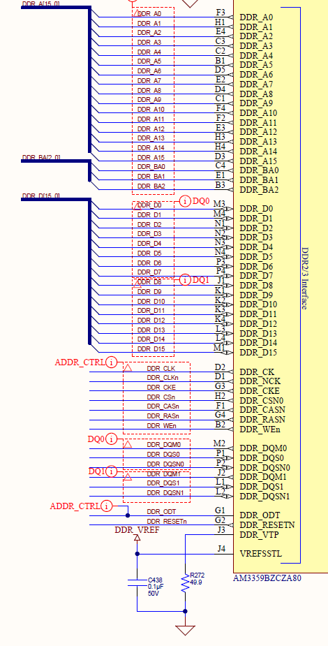
I'm trying to go through the process of DDR PHY register configuration using software leveling - next step in bringing up my AM3359.

The custom board design mostly follows the BeagleBoneBlack, so I've been working from this...

http://processors.wiki.ti.com/index.php/Sitara_Linux_Training:_Tuning_the_DDR3_Timings_on_BeagleBoneBlack

and also from this...

http://processors.wiki.ti.com/index.php/AM335x_DDR_PHY_register_configuration_for_DDR3_using_Software_Leveling

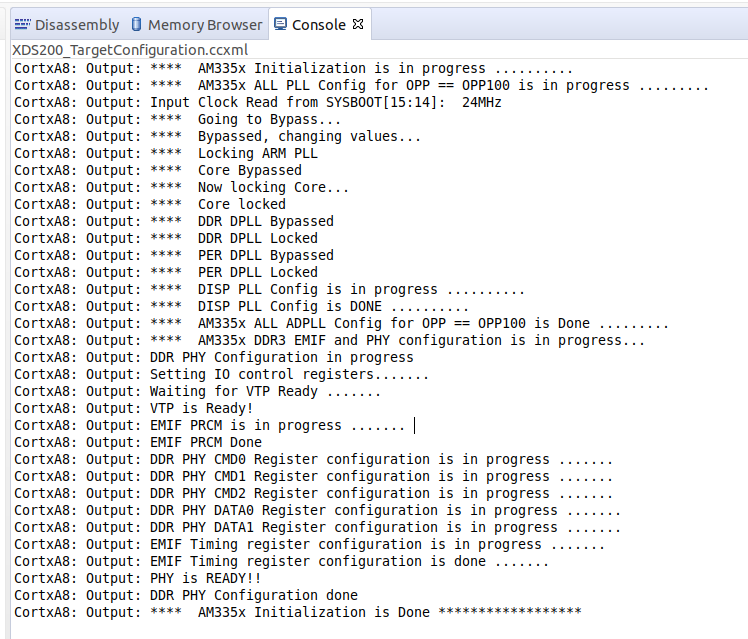
I've pulled all the values from the memory datasheet and made it through the DDR timing configuration spreadsheets, ending up with register settings that exactly matched those in the AM3358 starter kit gel file, although I've entered them into the BeagleBoneBlack gel file because of the 400MHz clock speed.  The gel file runs, I've loaded and run the ddr slave ratio tool on my custom board (connected to CCS with an XDS200), entered the values calculated from the ratio seed spreadsheet (using trace lengths from my PCB), and the program immediately tells me "Optimal Values Have Been Found!", but produces a table of zeros.  I've gone through the spreadsheets several times, confirmed the trace lengths, and tried with both gel files.  

I'm not sure where to go next.  Any suggestions would be greatly appreciated.

Thanks,

Eric

  • Eric,

    I'm sorry for the confusion.  Very recently we have overhauled the AM335x EMIF programming to give a more streamlined and better documented experience.  Please refer to the following app note and its associated spreadsheet:

    http://www.ti.com/lit/pdf/sprack4

    If you're using a single DDR3 IC (i.e. one 16-bit wide IC and not two 8-bit wide ICs), then you don't even need to run that tool.  That's covered in the new app note.  That guidance is slightly different than it was years ago where we always ran the tool.  Please use the updated spreadsheet to calculate all of your DDR-related parameters.  We consolidated years of learning into making this process much easier.

    I will see about redirecting some of the wiki pages you listed to the new spreadsheet so that other customers don't have the same confusion.  Thanks for mentioning it.

    Best regards,
    Brad

  • Hi Brad,

    Good idea to update the documentation.  I do only have a single DDR3 IC, so I won't do the software leveling bit, but I would like to use the GEL file referenced in the document to perform the DDR test scripts after updating the register settings.  However, the application note says the Code Composer GEL file and the Executable CCS .out file (which I know I don't need) can be found in the zip file link at the beginning of the application note, which I assume refers to the link to sprcaj0.zip.  The only file in that zip file is the spreadsheet, "AM335x_EMIF_Configuration_Tool_v2.xlsx".  Can you point me to the GEL file? 

    Thanks,

    Eric 

  • Hi Eric,

    sorry, it looks like we have something screwed up in the website links.  This link has the GEL file (along with v1 of the spreadsheet, so just ignore that)

    https://www.ti.com/lit/zip/SPRACK4

    Regards,

    James

  • Hi James,

    Thanks for the gel file.  I made it through the spreadsheet, pulling all of the values from the datasheet & from our layout.  Unfortunately, I'm still not having any luck communicating with the DDR3.  The initialization is completing, but when I try to run the AM335x_DDR Tests->DDR_DataTransferCheck, it fails miserably.

    The test ends with...

    :
    CortxA8: GEL Output: No of Failed locations are :: 0x000000F8
    CortxA8: GEL Output: No of Failed locations are :: 0x000000F9
    CortxA8: GEL Output: No of Failed locations are :: 0x000000FA
    CortxA8: GEL Output: Data Integrity check FailedCortxA8: Output: **** Device Type: G

    The intent was to mirror the design of the Beaglebone Black, but I just noticed that the order of the bits on the data bus (between the Sitara & DDR3 - see below) are reversed.  I expect this was for layout reasons, but would expect the masks & strobes to be reversed too (but they aren't).  Is this something that can be corrected in the configuration?  Are there any other configuration changes that need to be made to account for the reversal?  Any other ideas on what I can look for to get the memory working?

    Thanks,

    Eric