This thread has been locked.

If you have a related question, please click the "Ask a related question" button in the top right corner. The newly created question will be automatically linked to this question.

AM5728: Junction temperature formula difference

Part Number: AM5728

Hello TI,

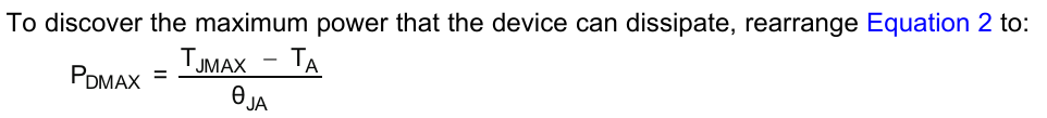
In the "Thermal Design Guide for DSP and ARM Application Processors" application report (link to the pdf below), the junction temperature equation seems to be different at two different places. In equation 2 and in equation 7, although they seem to refer to the same thing. In equation 2, you have Theta_CS*Theta_SA component and in equation 7 you have Theta_CS+Theta_SA component. I am assuming that one of it is a typo error. I would like to know which one is correct. OR if I am missing something then please let me know.

https://www.ti.com/lit/an/sprabi3b/sprabi3b.pdf

  • It is a typo.  Those thermal impedances should be added together.

    Tom

  • I am sorry. But, could you please elaborate a bit more?

    1) Do, you confirm that equation 7 is the correct one? 

    2) Could you also let me know, why the effective thermal resistance for complex systems is of the form 

    Theta_ja * (Theta_jc + Theta_cs + Theta_sa) / Theta_ja + (Theta_jc + Theta_cs + Theta_sa)

    instead of the sum of all the thermal resistances like Theta_jc + Theta_cs + Theta_sa, as they seem to be in series. 

    3) In that document, what exactly is the ambient temperature? I mean, is it the air temperature around the heatsink in the thermal control chamber? or is it the temperature on the heatsink which is in contact to the ambient air? 

    4) In the calculation of Pd_max (maximum power that the device can dissipate), what should be the value of Theta_ja? The equation is shown below from the "Understanding thermal dissipation and design of heatsink" document. 

  • Hello Tom,

    Do you have any update on my previous questions? Thank you so much for your time. 

  • Solid Repellent,

    You need to understand that these are all first-order equations that only provide estimates of performance.  Heat transfer is complex as it travels through many paths from heat source to ambient.  Also, since the ambient environment is the surrounding air, which may be moving and / or restricted, this becomes a 3-dimensional fluid dynamics problem.  Accurate estimates require use of complex 3D thermal analysis tools.

    From basic electrical circuit analysis, you know that 2 parallel resistors are combined by the following equation: (R1 * R2) / (R1 + R2).  In this first-order analysis, thermal resistances can also be combined similar to electrical resistors, in either series or parallel combinations.

    For this class of device, most of the heat is dissipated through the heat sink.  This is through the path junction-to-case, case-to-sink and sink-to-air which is represented as the thermal resistance sum Theta_JC + Theta_CS +Theta_SA.  However, there are other thermal paths.  These are summed in this generic Theta_JA term.  Equation 2 and Equation 7 then provide the complete effective thermal resistance where the generic Theta_JA is in parallel to the primary heat path through the heat sink.

    Answers below to direct questions:

    1.  Yes, I confirm that Equation 7 is correct for this application.

    2.  See discussion above on parallel thermal resistances.

    3.  Ambient temperature is the temperature of the surrounding air that carries away the heat.  It is some distance from the heatsink as the air close to the heatsink will be warmed by it.

    4.  This Theta_JA is the true thermal resistance from the junction to ambient considering all thermal paths.

    Tom