This thread has been locked.

If you have a related question, please click the "Ask a related question" button in the top right corner. The newly created question will be automatically linked to this question.

TMS320C6748: PowerOn reset can not boot normally using RC reset circuits.

Part Number: TMS320C6748

I make my own designed C6748 board.

The program is boot from eMMC.

I made 20 boards, 18 of them can boot normally from eMMC and run the program normally when power on.

But 2 of them cannot boot and run normally when power on, but the 2 boards can boot and run normally when I press the reset button.

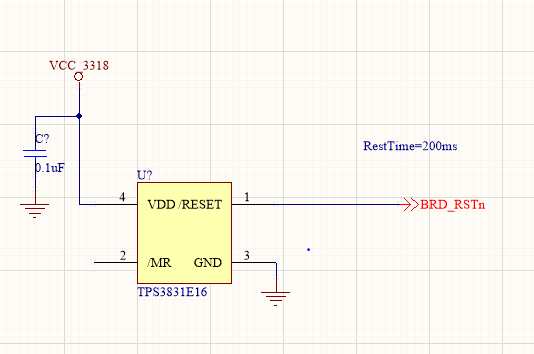
The schematic of the board is shown below. The VCC_3318 is 1.8V and the RC takes about 200ms.

I monitored the reset signal and compare the 2 boards with the other 18 boards, the reset signal waveform is just the same.

Question: Is it not accpetable for the C6748 to be reset using a RC reset circuit, since the signal changes too slow? I needs a steep changing signal?

Thank you.

Frank

  • Hi,

    Just this bit of your schematic does not give much information. Need to see the connection to the SoC. Also may be the power supplies circuit.

    Another thing to check is whether you maintain the reset signal active throughout the power on sequence. Note that RESET must be active until all power supplies have reached their nominal values.

    It will be good to share the scope measurement of the power-on sequence of a working board and a failing board if possible.

    Best Regards,
    Yordan

  • Hi Yordan,

           Thank you for your advice.

           And I'm sorry for replying you so later, these days I booked the TPS3831E16 reset chip and just placed it onto the board yesterday. 

           But the problem remains.

           Before I replace the TPS3831E16 chip , the schematic is below:     

         (VCC_3318 is 1.8V)

        After I replace the TPS3831E16 chip , only the RC reset circuit is replaced by the schematic below:


        But, the problem still occurs.

        Let me describe the phenomen in detail:

        1. 20 boards, only 2 boards have the problem. The 20 boards are powered on and off for 15 times for each one, only 2 boards failed to boot.

            The 2 boards failed about 5-10 times in the 15 times power on and off test.

        Below are tests made on the 2 boards with problem.

        2. I have a reset button on the RC reset schematic.

           After power up. If I press and then release the reset button, the 2 boards will boot succesuffly every time, never failed. That means the "warm reset" succeed every time.

           If I press the reset button before power up, and release the reset button after power up. It has the same probability that the boot will failed. That means the "Power-On Reset" failed sometimes for these 2 boards.

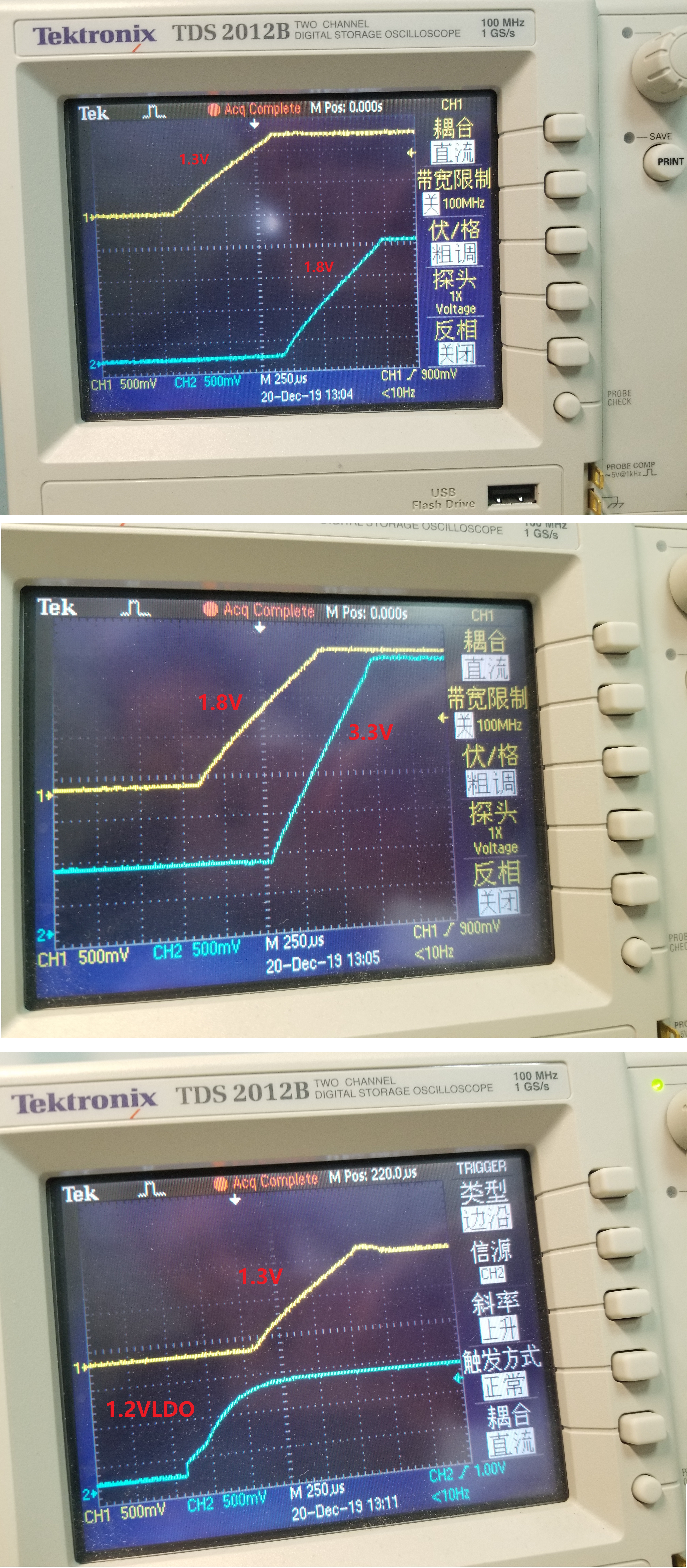
        3. I monitored the power up sequence with oscilloscope, I'm sure the sequence is right. 

            1.2V  then    1.3V   then    1.8V   then    3.3V  according to the schematic.


            4. The 2 boards have no other problems, they can work normally for many hours after boot up.


          Please help! Thank you!

    Frank

  • Hi Frank,

    Can you provide a scope shot showing the timing of RESET in the case where the 2 boards fail to boot?

    Check clocks are enabled and satisfy the timings in Table 6-1 in the TRM (https://www.ti.com/lit/pdf/spruh79)
        -What is the clock source? Note the Errata Usage Note 2.1.4 System-Level ESD Immunity Usage Note (https://www.ti.com/lit/pdf/sprz303)
        -A sharp clock transition is required to avoid the time in the input threshold region, where noise can cause glitches.
        -Compare the passing and failing boards (when the issue occurs and when it does not)

    Check boot pins latching
        - do you have JTAG access on these boards?
        - after one of the 2 boards fails to boot and run normally, can you connect to it with CCS through JTAG? dont use a GEL file since it will reinitialize the device
        - in the register window, observe the value of BOOTCFG (0x01C1 4020) and Program Counter (PC)
        - Also observe the Program Counter - as it might tell us if the program is still executing the bootloader
        

    Please note that there will be a delay in responses next week due to the holidays.   

    Regards,
    Mark

  • Hi Mark,

           Thank you very much.

           Following your advice, I'm working on it and will update as soon as I have a result.

           Merry christmas.

    Frank

  • Hi Mark,

          I've found the cause of the problem. The DDR chips on the two boards are not well welded, the BGA pins are bad connected to the board.

          When I press the DDR chips with a pen, it can boot up every time!

          The chips have now been re-welded. Now the 2 boards can boot up normally.

          But with your advice in the last reply. I still have 2 questions:

         1、According to the Errata Usage Note 2.1.4 System-Level ESD Immunity Usage Note, " If ESD robustness is a concern, it is strongly recommended to avoid using the internal oscillator as a clock source. An external 3.3V clock source with a resistor voltage divider as in Figure 2 can be used to
    externally generate the required 1.2V input clock."

              But in my system, I have to use the internal oscillator. Because using external 3.3V clock source with a resistor voltage divider, the resistors must be small (for example, 165 and 100 ohm). 3.3/265=12.5mA, concerning the 50% duty cycle, 6.25mA current is wasted on the resistor. My system is a battery powered system, and the 6.25mA is too much waste. But 1.2V external oscillator does not exist. And the resistor can not be large, because the input impedance of the OSCIN is low.

             Do I have better choise? To make System-Level ESD Immunity, if I have to use the internal oscillator.

         2、I read BOOTCFG, and the BOOTCFG is alright.

              According to Advisory 2.3.23, it is better to make RPDmax<2.03k ohm and RPUmax<2.33k ohm (in case of 1.8V). To make sue the BOOTCFG will not be wrong during power up.

              In my case, I use 4.7k to pull up and 10k to pull down. And now the device can boot succesuffly every time.

              Do you suggest me to change to RPDmax<2.03k ohm and RPUmax<2.33k ohm?

             Thank you.

    Frank

    RPDmax

  • Frank

    If your end product needs to go through System ESD testing , we strongly recommend using an external oscillator. Other robustness recommendations are listed in the errata but may not provide as much immunity as an external oscillator. 

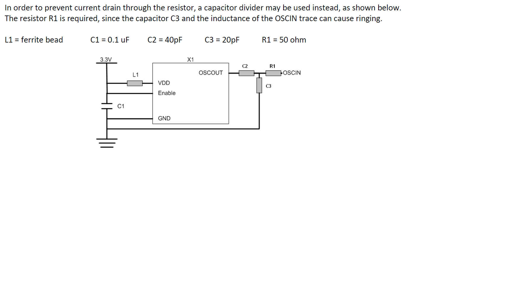
    If current drain is a concern, you can evaluate putting a cap divider circuit instead (we did limited testing with this, and it seemed ok too) 

    On your query 2 , we strongly recommend that you follow the recommendations in the errata, if you think you are susceptible to it. You are basing your "working fine" on a single board or maybe 20 board. You can see more variation in process once you build larger quantity of boards, so I would not recommend you relying on a single board observation.

    Hope this helps.

    Good luck

  • Hi Mukul Bhatnagar,

           Thank you so much for your answer.

           Q1. Since C2 and C3 are in series connection, the totol cap from OSCOUT to GND would be Ctotal=20//40pF=13.33pF.

                  f=24MHz, then |Zc|=1/(2*pi*f*Ctotal)=497ohm, about the same level using the resistor solution. The current drain is still big. 3.3/497=6.6mA, concerning the 50% duty cycle, 3.3mA current is wasted on the caps. Is there any way to low the current drain?

           Q2. I would follow your advice.Thank you so much.

    Frank