Hi Ti team,
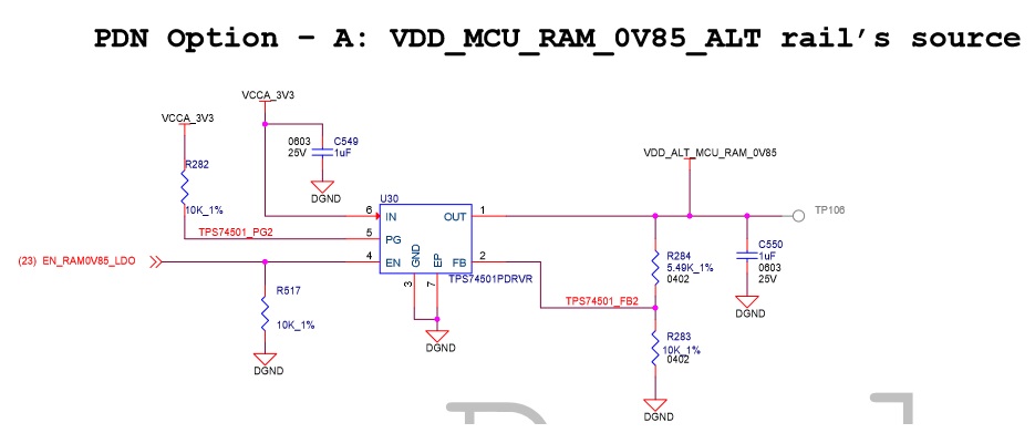
The EVM has some ALT power rail sources, what's the purpose for these? Any risk if we remove them?
Thanks a lot
B.R
Y.L
Hi Ti team,
The EVM has some ALT power rail sources, what's the purpose for these? Any risk if we remove them?
Thanks a lot
B.R
Y.L